Getting Started with RS9116W and an EFx32 Host#
This guide describes how to get started developing a RS9116W application on an EFx32 embedded host MCU using the WiSeConnect™ Simple Application Programming Interface (SAPI). For quick evaluation using only the EVK and a PC instead see Getting Started with PC using AT Commands.


Getting started with application development on an EFx32 involves the following steps:
Download and Install Simplicity Studio#
Simplicity Studio is available for download at www.silabs.com/simplicity-studio. The steps outlined in this getting started guide require Simplicity Studio version 5.1.2 or later.
During installation, be sure to install the Technology Type: 32-Bit Microcontrollers. More details can be found at Simplicity Studio Installation Instructions
Note! The WiSeConnect™ Software Driver Package is automatically downloaded by Simplicity Studio. More details can be found in the section, Explore the WiSeConnect™ Software Driver Package.
Choose a host MCU Development Board#
The example projects provided with the WiSeConnect™ Software Driver Package are designed to work out-of-the-box with the EFR32MG21 Wireless Starter Kit (SLWSTK6006A) or EFM32GG11 Starter Kit (SLSTK3701A) and the RS9116W Wi-Fi + Bluetooth Development Kit. Project files are provided for both the EFR32MG21 radio board version A (BRD4180A) and version B (BRD4180B), EFM32GG11 radio board version (BRD2204A)
The WiSeConnect™ driver software also works with other embedded host MCUs. Details on porting the driver to other host MCUs can be found in the RS9116W SAPI Porting Guide.
Update the RS9116W Firmware#
When you first receive a RS9116 EVK, or when updating to a new version of the WiSeConnect™ Software Driver Package, we recommend updating the RS9116W firmware to the latest available version. There are several ways to update firmware, but the recommended method to get started is outlined in the section, Updating RS9116W Firmware.
Note!
Disconnect the RS9116W EVK from the host MCU board before updating the firmware, the host MCU connections may interfere with the update process.
Connect the RS9116W EVK to the host MCU development board#
For EFR32MG21 host MCU#
Connect the EFR32 Starter Kit, EXP adapter board and RS9116 EVB as illustrated in the following picture:
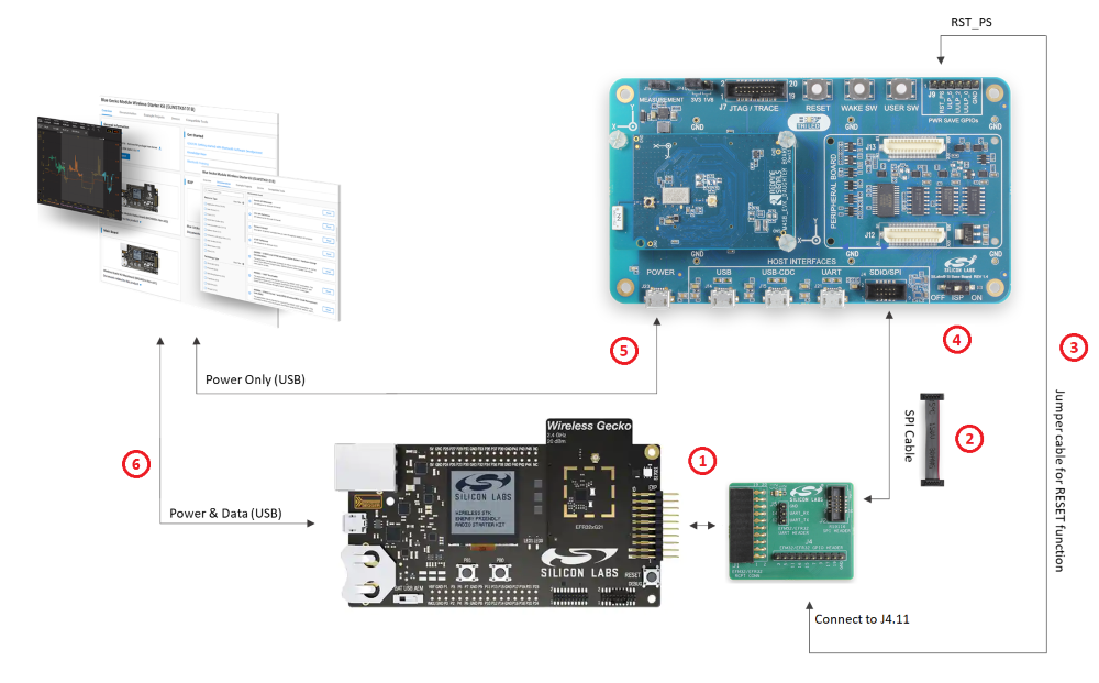

Note! The EXP adapter board is included in the RS9116 Evaluation Kit. If you have an older RS9116 Evaluation Kit that does not include the EXP adapter board, please request one through your local sales representative.
STEP 1. Connect the EXP adapter board to the EFR32 starter kit EXP header.
STEP 2. Connect the EXP adapter board to the SPI connector of the RS9116 EVK using the 10-pin ribbon cable provided with the RS9116 EVK.
STEP 3. Connect the RST_PS pin on the RS9116 EVK to the pin labeled 11 on the J4 header of the EXP adapter board using a jumper wire.
STEP 4. Set the ISP switch on the RS9116 EVK to the OFF position.
STEP 5. Connect the RS9116 EVK to a PC using the USB interface labeled POWER. Note that this connection only provides power to the EVK. There is no USB communication over this connection.
STEP 6. Connect the EFR32 Starter Kit to a PC using the Mini USB connector on the EFR32 Starter Kit.
Complete hardware details of the RS9116 EVK can be found in the RS9116 EVK User's Guide.
Power Save GPIO Connections#
The instructions above enable basic operation between the host MCU and RS9116. Some low power examples require additional connections of the Ultra Low Power (ULP) GPIOs as detailed in the table below. These details are valid for any example provided in the WiSeConnect™ SDK unless otherwise noted in the readme documentation of a particular example.
Signal Name | EXP Adapter Board | RS9116 EVK | Notes |
|---|---|---|---|
UULP_0 / UULP_3 | J4 Pin 9 | J9 Pin 5 | If using a RS9116 EVK version 1.4 or newer connect UULP_0. Otherwise connect UULP_3 |
UULP_2 | J4 Pin 7 | J9 Pin 4 |
For EFM32GG11 host MCU#
Connect the EFM32 Starter Kit and RS9116 EVB as illustrated in the following picture:
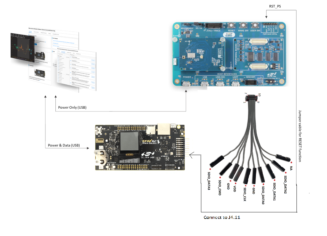

STEP 1. Connect one end of the SDIO connector to EFM32 board using the SDIO Pin Configuration Table given below.
STEP 2. Connect the other end of SDIO connector to the RS9116 EVK.
STEP 3. Connect the RST_PS pin on the RS9116 EVK to the PIN11 on EFM32 board using a jumper wire.
STEP 4. Set the ISP switch on the RS9116 EVK to the OFF position.
STEP 5. Connect the RS9116 EVK to a PC using the USB interface labeled POWER. Note that this connection only provides power to the EVK. There is no USB communication over this connection.
STEP 6. Connect the EFM32 Starter Kit to a PC using the Mini USB connector on the EFM32 Starter Kit.
Complete hardware details of the RS9116 EVK can be found in the RS9116 EVK User's Guide.
SDIO Pin Configuration Table :#
Pins on EFM32 | On Expansion Header | Pins on RS9116 EVK |
|---|---|---|
PIN# | Signal | PIN# |
14 | SDIO_DAT2 | 9 |
12 | SDIO_DAT3 | 1 |
8 | SDIO_CMD | 2 |
10 | SDIO_CLK | 5 |
6 | SDIO_DAT0 | 7 |
4 | SDIO_DAT1 | 8 |
1 | GND | 3 |
20 | 3V3 | 4 |
Power Save GPIO Connections#
The instructions above enable basic operation between the host MCU and RS9116. Some low power examples require additional connections of the Ultra Low Power (ULP) GPIOs as detailed in the table below. These details are valid for any example provided in the WiSeConnect™ software package unless otherwise noted in the readme documentation of a particular example.
RS9116W PWR SAVE GPIOs peripheral J9 Header Pin | EFM32 Pin# | Function | Comment |
|---|---|---|---|
UULP_0 / UULP_3 | 5 | GPIO | If using a RS9116W EVK version 1.4 or newer connect UULP_0. Otherwise connect UULP_3 |
UULP_2 | 3 | GPIO |
Open a Featured Example Project in Simplicity Studio#
The WiSeConnect™ SDK includes a number of examples that are featured in Simplicity Studio. A list of the featured examples along with documentation detailing the operation each example can be found in: Featured Examples. More details on the contents of the software package can be found in: Explore the WiSeConnect™ Software Driver Package.
STEP 1. Open Simplicity Studio and navigate to the Launcher perspective.
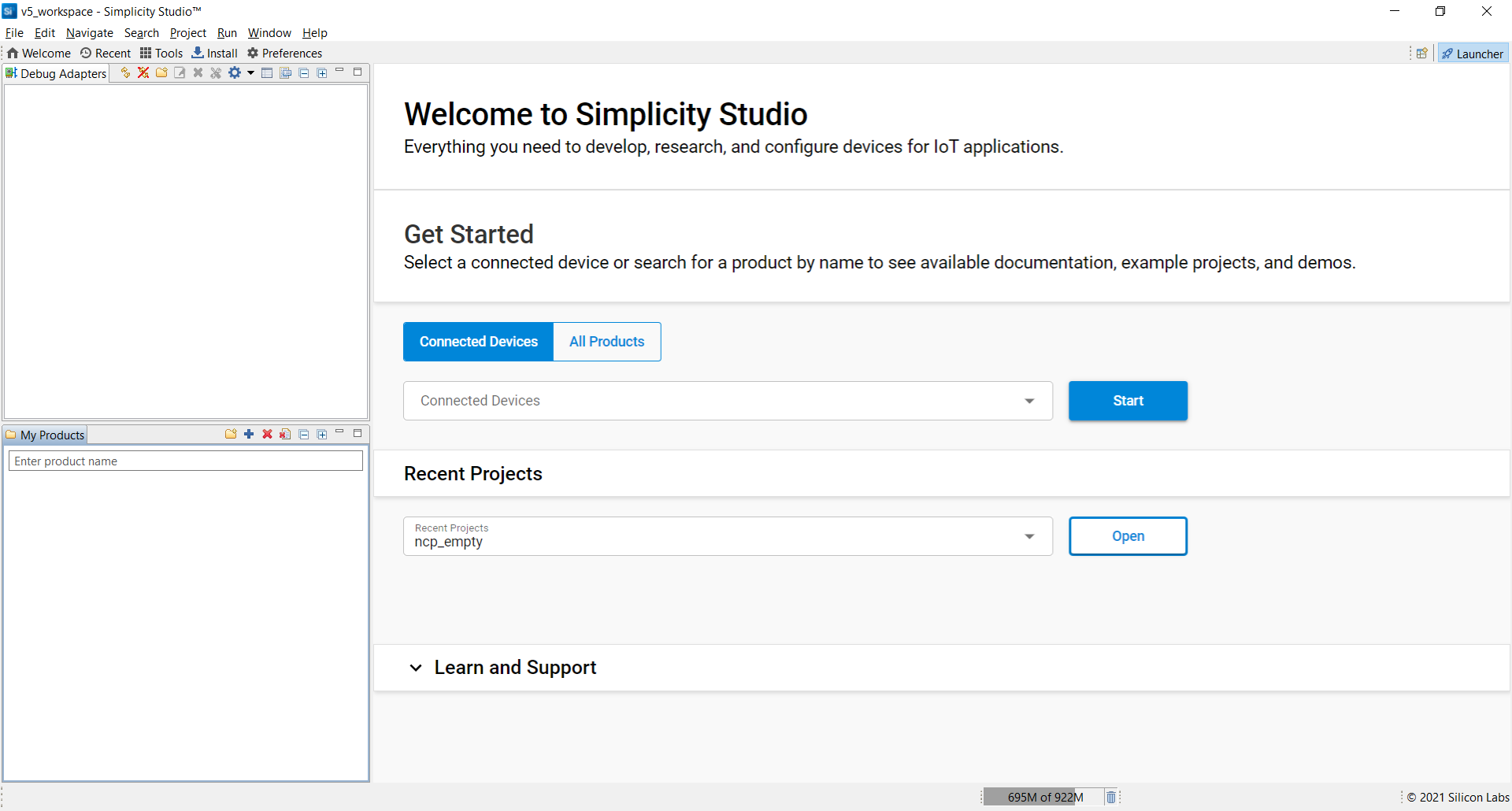

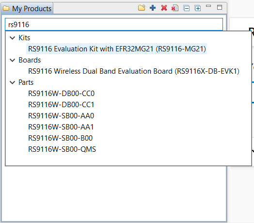
STEP 2. Under My Products add the RS9116 Evaluation Kit with EFR32MG21 by typing RS9116 then selecting the kit.

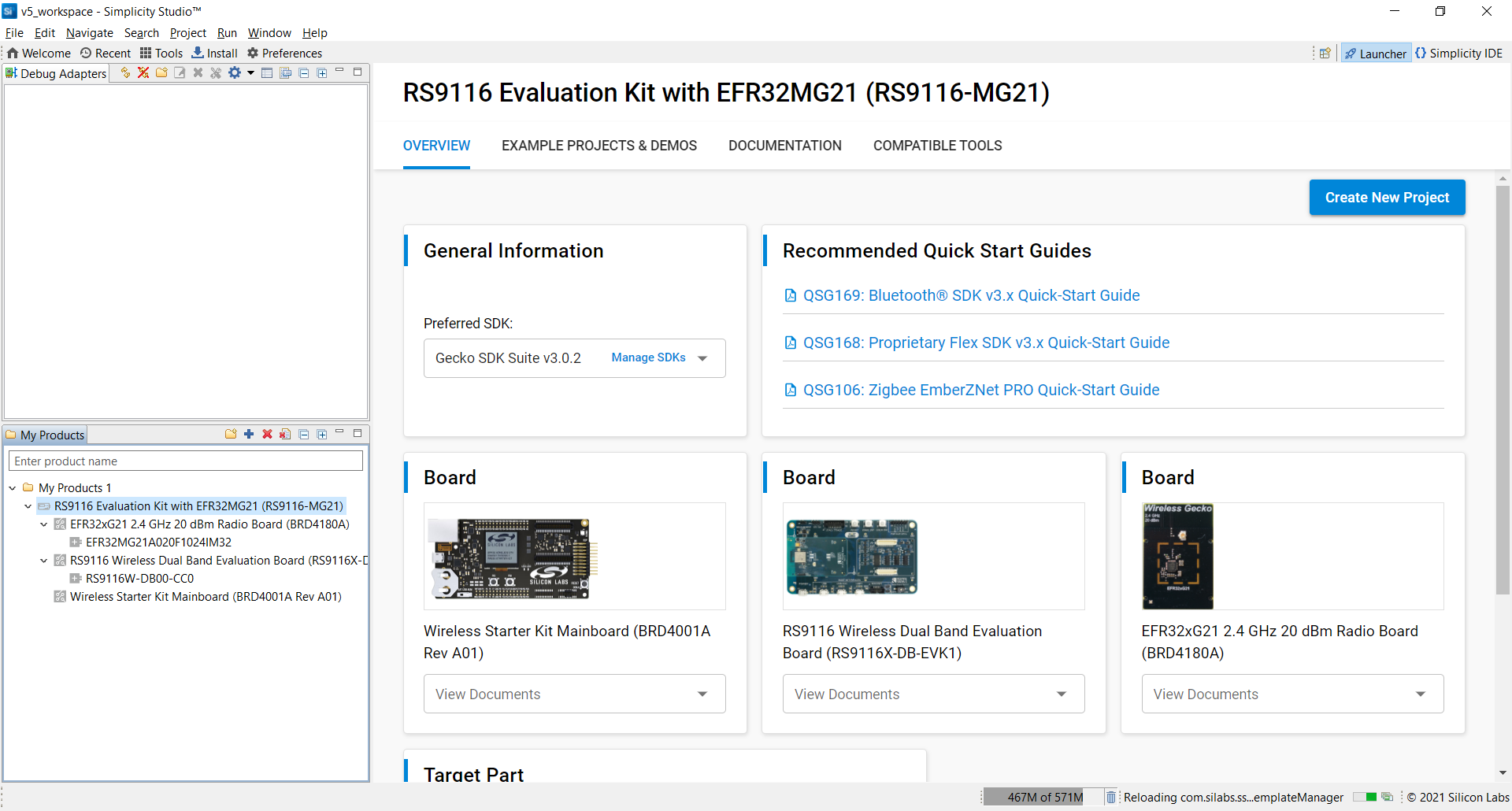
The RS9116W Overview page should now display information about the RS9116W and EFR32MG21 kits.

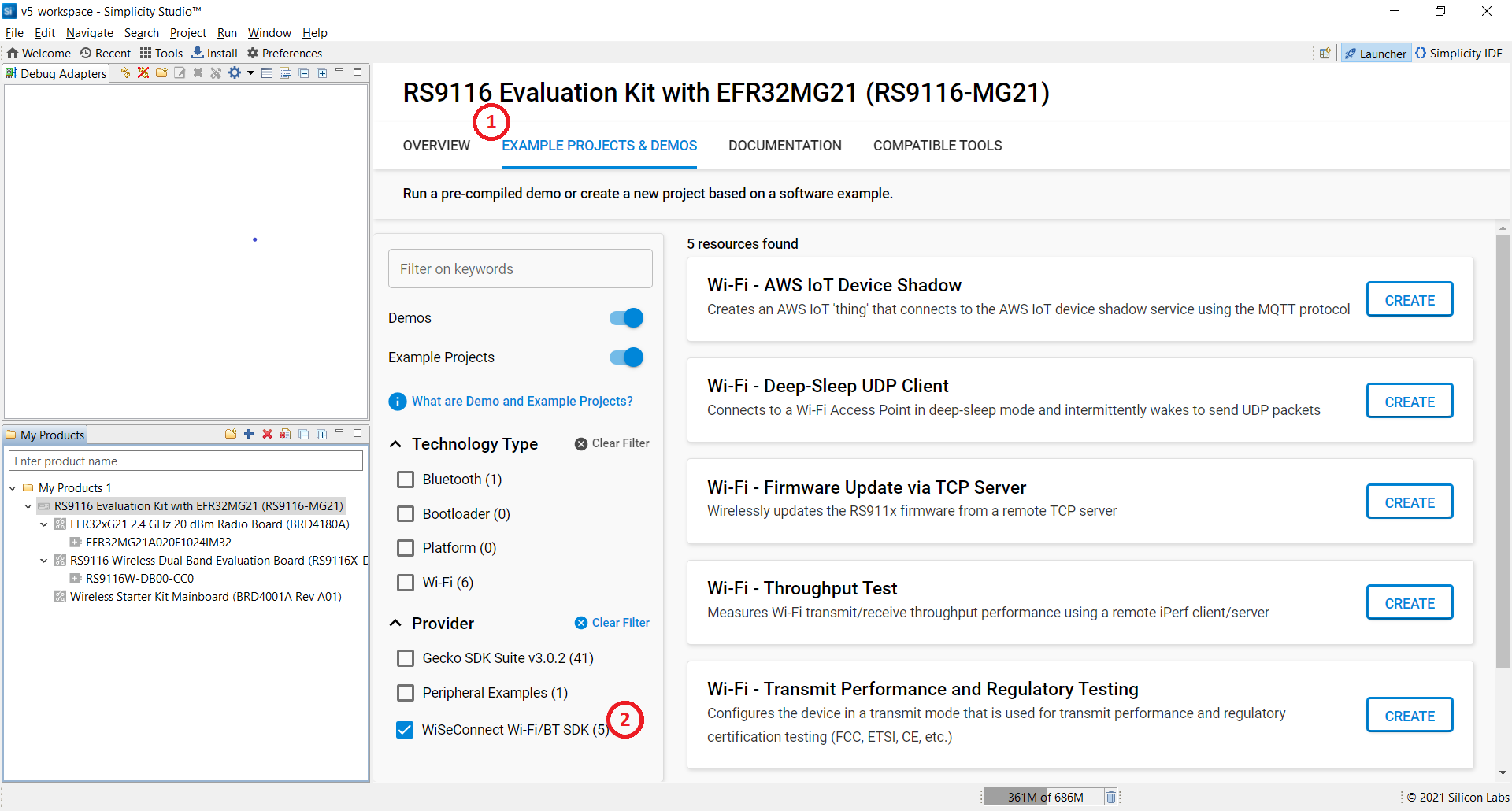
STEP 3. With the product RS9116 Evaluation Kit with EFR32MG21 selected, navigate to the example projects by clicking on Example Projects & Demos then filter by the RS9116 WiSeConnect SDK as shown below.

Note!
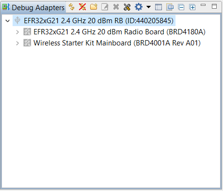
The RS9116 Evaluation Kit with EFR32MG21 that was added in the previous step specifies the EFR32MG21 radio board version B (BRD4180B). If instead you are using a EFR32MG21 radio board version A (BRD4180A) then, prior to selecting an example project, you must select the board under Debug Adapters as shown below.

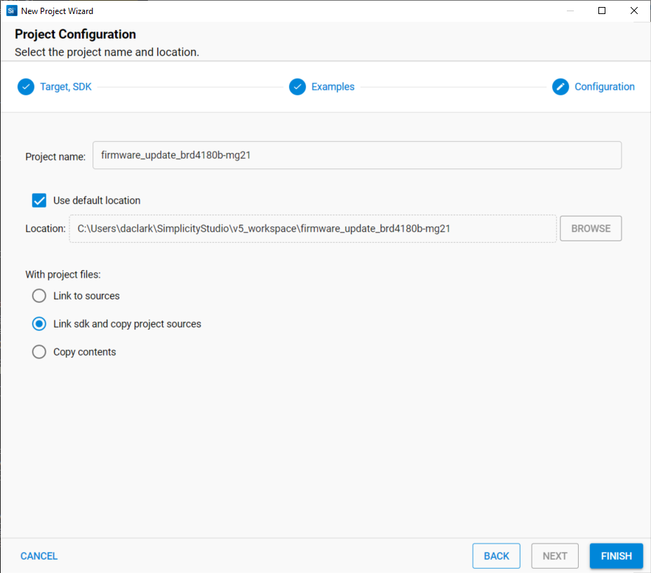
STEP 4. Click the Create button for the project that you wish to open. This will display the New Project Wizard which will allow you to rename your project, choose the location of your project and select whether you want the project files linked to the original location or copied into the new project location. Typically, the default settings should be used for all options. Click Finish to exit the wizard and create the new project.

Note!
The mention of "SDK" in the New Project Wizardand in the Simplicity IDE refers to the EFR32 platform SDK known as the Gecko SDK (GSDK) and not the RS9116 WiSeConnect™ SDK.
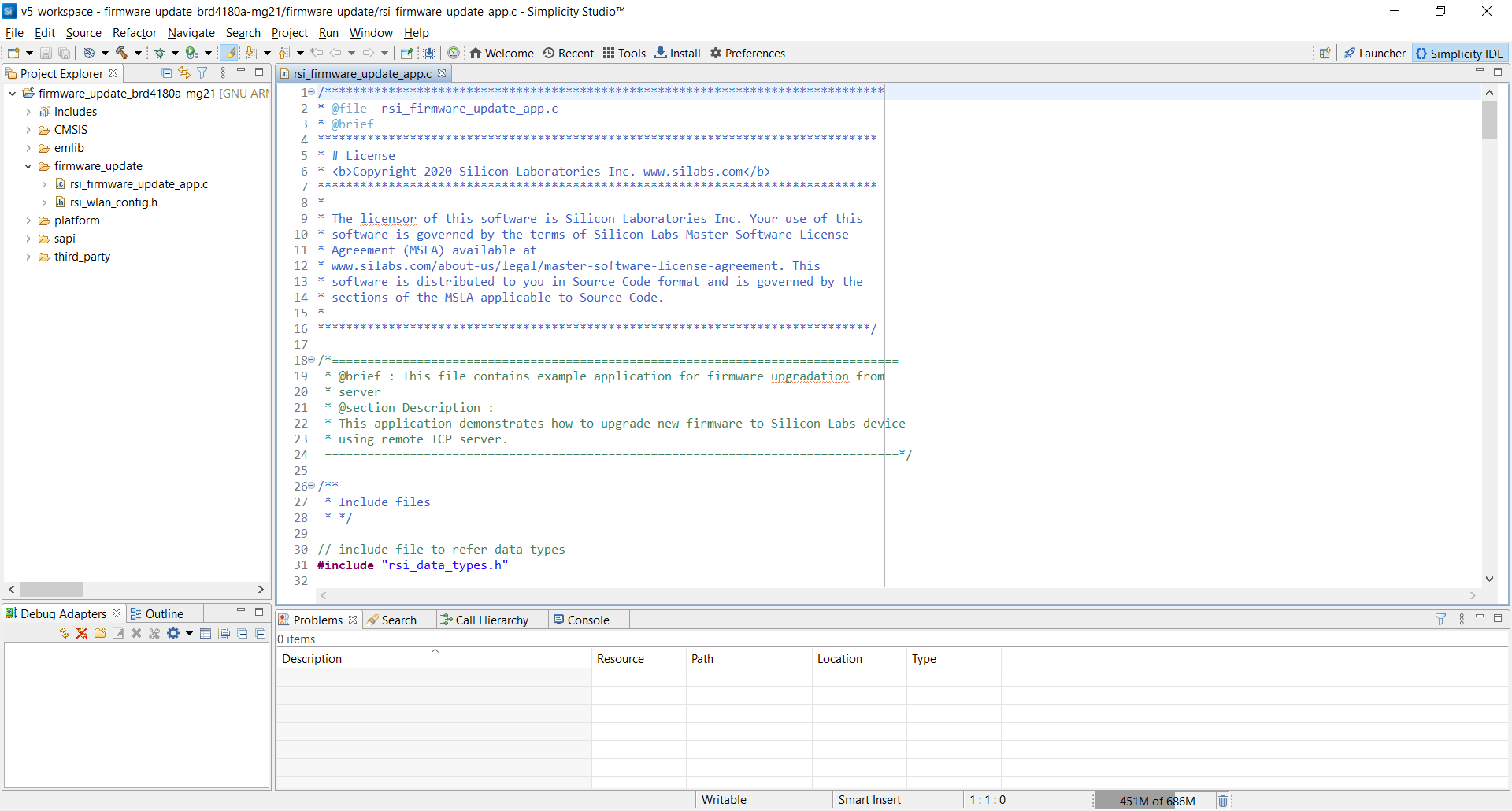
STEP 5. After creating the project, Simplicity Studio will launch the Simplicity IDE allowing you to build, run and debug the project.

Build, Run and Debug an Example Project on the Development Kit#


You can flash, run and debug the newly created example project simply by clicking on the Debug icon in the Simplicity IDE toolbar. This will build the project, flash it onto the attached STK and open the Debugger Perspective. Unless configured otherwise, the debugger will automatically break execution at the beginning of main allowing the user to step, run, or otherwise debug the application. More details on using the debugger tools can be found at: Using the Debuggers.
To build the project without flashing and executing it, simply click on the Build icon in the Simplicity IDE toolbar. This will build the selected default configuration (debug or release).
A pre-built image can be programmed onto a device using the Flash Programmer which is available by clicking the Program icon in the Simplicity IDE toolbar.
Example specific details such as how to configure and operate the example can be found in Example Applications. The same information is also available in the readme file available with the example project source code.
Explore the WiSeConnect™ Software Driver Package#
Simplicity Studio automatically downloads the official WiSeConnect™ SDK repository from the Silicon Labs GitHub space. Therefore no action is required to integrate the software into Simplicity Studio.
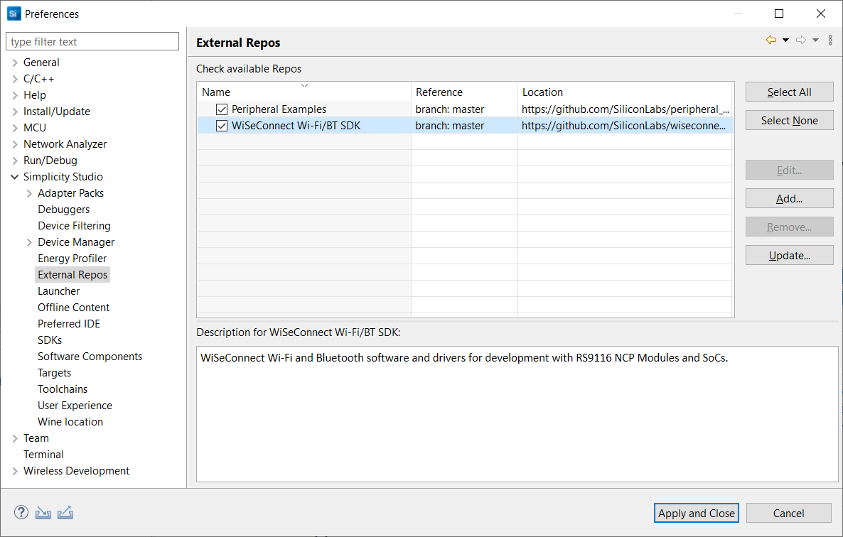
For advanced situations, the integration between Simplicity Studio and the The WiSeConnect™ SDK GitHub repository can be managed using the External Repos settings in Simplicity Studio. To view or edit the external repos settings go to Preferences > Simplicity Studio > External Repos as shown below. Here you can add, edit, update, or remove repos. You can also select a specific branch, tag or a commit that you would like to use.

Once downloaded, Simplicity Studio will store the repository in the Simplicity Studio installation folder under ./developer/repos. On a Windows PC this is typicall found at C:\SiliconLabs\SimplicityStudio\v5\developer\repos. You can explore the WiSeConnect™ SDK here.
Note! Simplicity Studio will not download the full contents of the WiSeConnect™ SDK GitHub repo until the user opens one of the features example projects as described in: Open a Featured Example Project in Simplicity Studio
The WiSeConnect™ SDK is organized into the main folders described below.
Folder | Description |
|---|---|
| Contains host MCU example projects. The example projects are divided into |
| Contains RS9116 firmware image |
| Contains platform specific source code for various available platforms. Other platforms can be supported by following the RS9116W SAPI Porting Guide. |
| Contains various resources for the example projects and sapi including device certificates and scripts. |
| Contains the source code files for the WiSeConnect™ Simple Application Programming Interface (SAPI). |
| Contains third party source code and tools such as freeRTOS, AWS SDK and more. |
| Contains varous utilities useful for evaluation and application developent. |
Example Project Types#
The examples included in the WiSeConnect™ SDK are divided into the following types:
Featured - Full featured projects that perform a key aspect of RS9116W evaluation or use-case. Featured examples are available directly from Simplicity Studio. Using a featured example is described in :Open a Featured Example Project in Simplicity Studio
Snippets - Smaller projects that focus on one particular feature or API. Snippets can be easily imported into Simplcity Studio as described in: Import Snippet Example Projects into Simplicity Studio.
AT commands - Pre-built Tera Term scripts used for evaluating the RS9116W directly from a PC. More details can be found in: Getting Started with RS9116 EVK and WiSeConnect™.
Import Snippet Example Projects into Simplicity Studio#
Snippet example projects are available in the WiSeConnect™ SDK in the subfolder folder ./examples/snippets. More information about the location of the WiSeConnect™ SDK, the folder structure and the example types can be found in: Explore the WiSeConnect™ Software Driver Package.
Snippet example projects can be easily imported into Simplicity Studio using the steps below:
For EFR32MG21 host MCU#
STEP 1. Select File > Import ... from the Simplicity Studio menu.
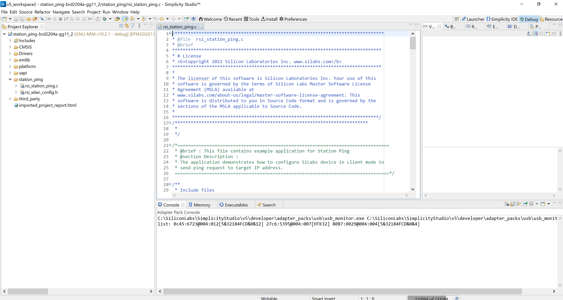
STEP 2. Click Browse and navigate to the projects folder in the snippet example that you are wanting to import. In this example we are using the WLAN Station Ping example found at C:\SiliconLabs\SimplicityStudio\v5\developer\repos\wiseconnect\examples\snippets\wlan\station_ping\projects.
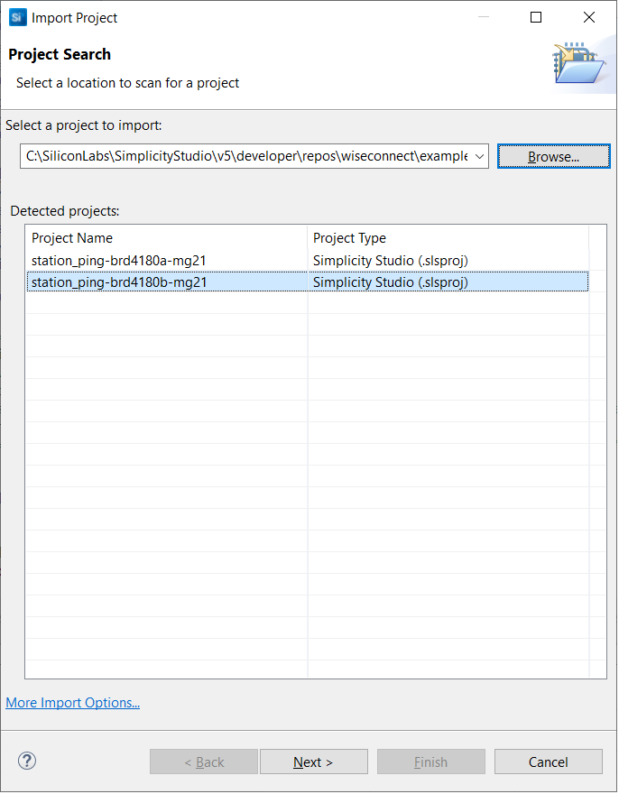

STEP 3. The project names include the EFR32 board number associated with the project (e.g. brd4180a). Select the project associated with the the board you are using and click Next.

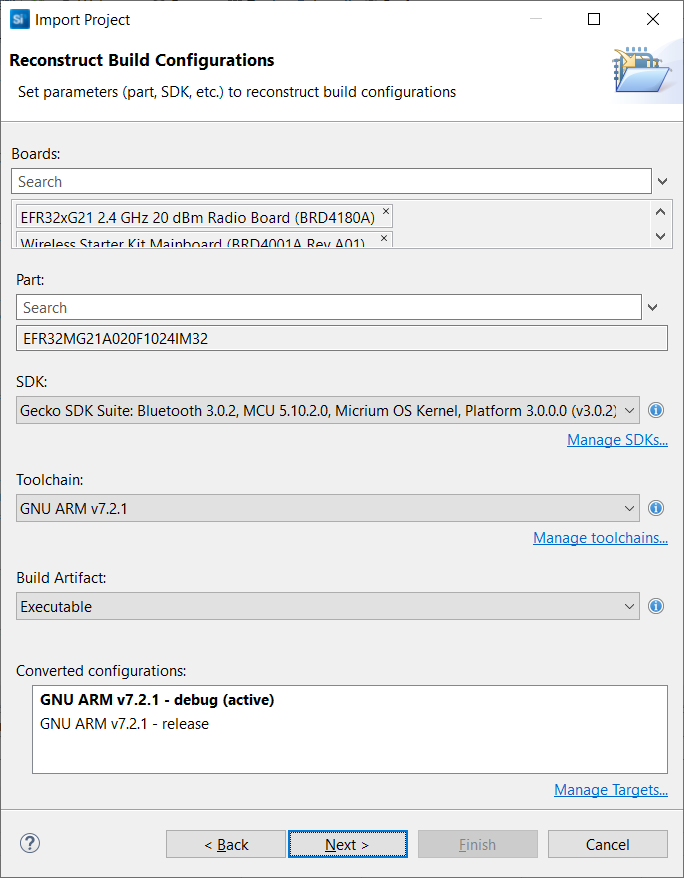
STEP 4. Ensure there are no unresolved settings then click Next

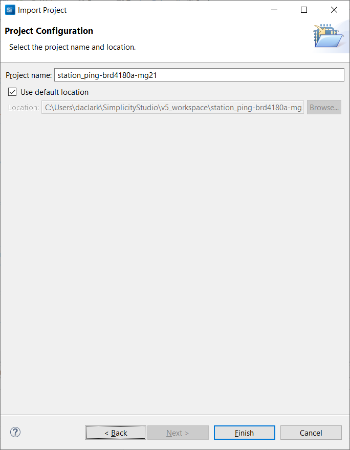
STEP 5. Click Finish. The Simplicity IDE will be displayed with the imported project. You can now build, run and debug the project.
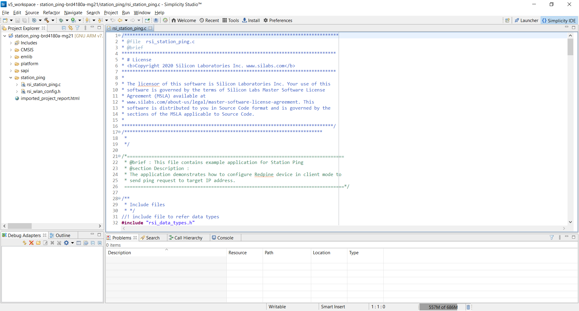

For EFM32GG11 Host MCU#
STEP 1. Select File > Import ... from the Simplicity Studio menu.
STEP 2. Click Browse and navigate to the projects folder in the snippet example that you are wanting to import. In this example we are using the WLAN Station Ping example found at C:\SiliconLabs\SimplicityStudio\v5\developer\repos\wiseconnect\examples\snippets\wlan\station_ping\projects.
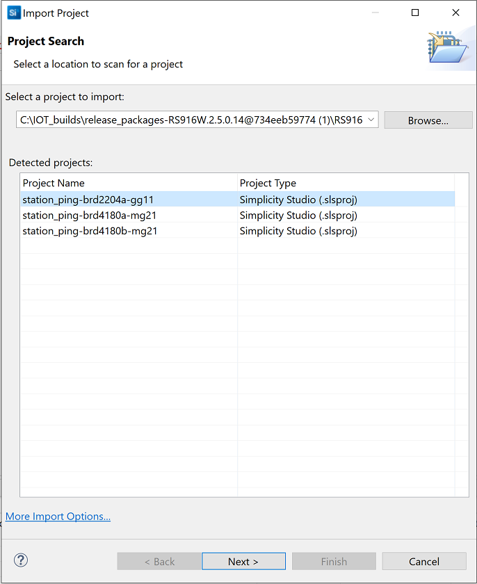

STEP 3. The project names include the EFM32 board number associated with the project (e.g. brd2204a). Select the project associated with the the board you are using and click Next.
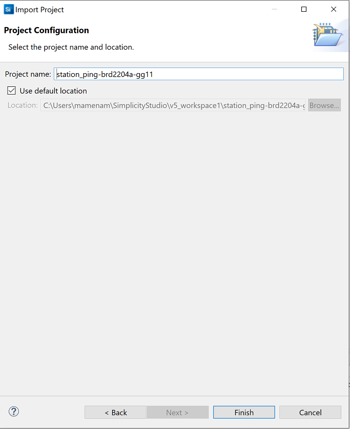

STEP 4. Ensure there are no unresolved settings then click Next
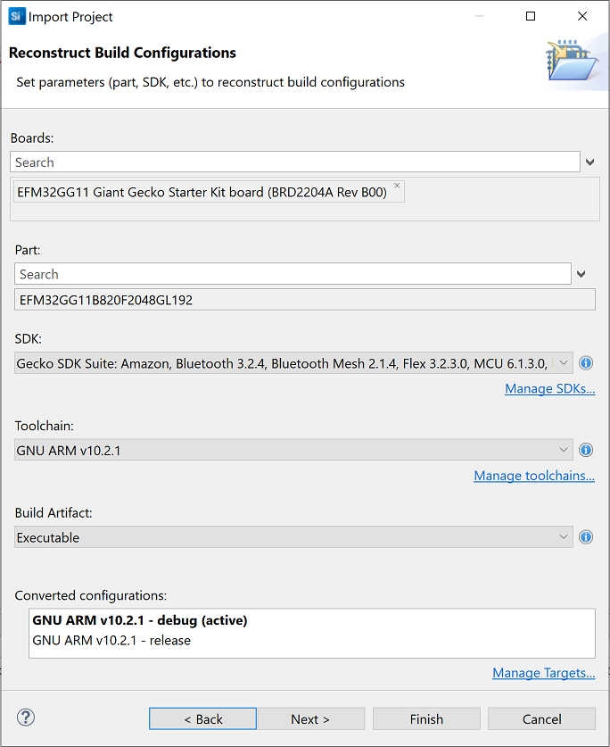

STEP 5. Click Finish. The Simplicity IDE will be displayed with the imported project. You can now build, run and debug the project.
