Channel Sounding Capabilities & Configurability#
Channel Sounding performance depends on a coordinated set of radio, scheduling, and algorithm parameters. This page explains how to configure the SoC and NCP in Channel Sounding applications.
High-level capability matrix with build-time macro references
Focused CS procedure parameter table (intervals, repetitions, steps)
Detailed sections on scheduling strategy, antenna configuration (tone, sync, offset), algorithm mode behavior, channel map presets & custom constraints
Guidance for multi-connection CS scheduling
Configuration Methods#
Build Time#
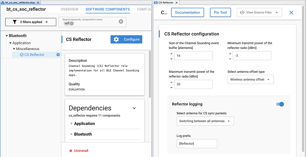
At build time, the default initiator and reflector configurations are set via the header files (cs_initiator_config.h, cs_reflector_config.h) or in the Component Editor (SoC only) as shown below.

The table below provides the locations of the header files for SoC and host-NCP applications.
Mode | Initiator header | Reflector header | Notes |
|---|---|---|---|
SoC |
|
| Header or Component Editor (regenerates config/*.h) |
NCP |
|
| The header files referenced are from the host application project; NCP-side component changes are ignored unless manually mirrored. |
Runtime#
The host and SoC applications initialize the initiator and reflector roles with the default config structs. They can be overwritten by modifying the fields of the cs_initiator_config_t and cs_reflector_config_t structures.
The general recommendation is to use runtime overrides to experiment and push stable values back into macros for production.
CS Capabilities#
The table below lists each Channel Sounding feature with its supported and unsupported options and whether it’s configurable or fixed in the stack. If configurable, the relevant macro is provided.
Feature | Supported | Not Supported | Config |
|---|---|---|---|
Main Mode | Mode 1 (RTT), Mode 2 (PBR) | Mode 3 (PBR + RTT) |
|
Submode | Mode 1 | Mode 2, Mode 3 |
|
Channel Selection Type | Algorithm #3b | Algorithm #3c | Fixed¹ |
RTT Payload Type | RTT Fractional 96‑bit sounding sequence | All other RTT payload variants | Fixed¹ |
CS Sync PHY | 1M | 2M, 2M 2BT | Fixed¹ |
Connection PHY | 1M, 2M | - |
|
Procedure Repeat Mode | 0 (free-running), 1 (single-shot) | >1 |
|
Mode 0 Step Count | 1–3 | - |
|
Quality Indicators | None | Tone Quality Indicator, Attack Detection Metric, TX SNR control | - |
¹ Single supported value
RTL Algorithm Modes#
Three algorithm modes are supported to fit different use cases:
SL_RTL_CS_ALGO_MODE_REAL_TIME_BASIC: use this mode to track moving targetsSL_RTL_CS_ALGO_MODE_REAL_TIME_FAST: use this mode to track fast-moving targets requiring low latencySL_RTL_CS_ALGO_MODE_STATIC_HIGH_ACCURACY: use this mode to estimate the distance of stationary objects.
Similar to the CS configuration, the RTL algorithm mode is configured in the config/cs_initiator_config.h file defined by CS_INITIATOR_DEFAULT_ALGO_MODE macro.
In the SoC initiator application, by default, the initiator uses the REAL_TIME_FAST mode. STATIC mode can be selected by pressing Button 1 on the WSTK at startup. Press BTN1 on the WSTK while resetting the device to select STATIC mode.
Important notes:
In STATIC mode, a valid distance estimation is produced for every 100 CS procedures. Hence, extra care must be taken to the returned error code by the algorithm.
SL_RTL_ERROR_ESTIMATION_IN_PROGRESS is returned by
sl_rtl_cs_processandsl_rtl_cs_get_distance_estimatemethods when distance estimation is not ready.SL_RTL_ERROR_SUCCESS is returned by
sl_rtl_cs_processandsl_rtl_cs_get_distance_estimatemethods when distance estimation is ready.
In STATIC mode, the algorithm estimates distances with a resolution of 0.1 m.
There is currently no observable difference in the results between STATIC and REAL_TIME modes in RTT.
CS Procedure Parameters#
The following table highlights the CS procedure parameters typically modified on the initiator to trade off update rate, power consumption, and measurement robustness for the selected RTL algorithm. It also provides the macro(s) that configure the parameter.
CS Procedure Parameter | Supported Values | Config |
|---|---|---|
Procedure Interval | 1-255 |
|
Procedure Scheduling | Frequency/Energy optimized, Custom |
|
CS Tone Antenna | ACI indices (0,1,4,7) |
|
Channel Map Preset | HIGH(72), MED(37), LOW(20), Custom |
|
TX Power | 10 dBm |
|
In addition to the above configurations, logging, RAS profile, and other general settings for the initiator and reflector roles are configurable via the initiator and reflector components.
Note: See Supported CS Step Data Combinations for the supported combinations of measurement mode, RTL algorithm mode, and channel map.
Default Configuration: Sample applications default to
REAL_TIME_FASTalgorithm mode,HIGHchannel map (72 channels), frequency-optimized procedure scheduling, and free-running repeat mode (0). Adjust these per application needs.
Advanced Configuration Topics#
Channel Maps#
The standard defines 79 RF channels with 1 MHz spacing in the 2.4 GHz band, with channel indices ranging from 0 to 78. The allowed range for channel sounding usage is a minimum of 15 channels and a maximum of 72 channels. Channels with indices 0, 1, 23, 24, 25, 77 and 78 are excluded due to overlap with primary advertising channels.

By default, the examples use all the allowed channels. However, this can be adjusted if using fewer channels is necessary to prioritize speed and energy efficiency over the highest possible accuracy.
The table below summarizes the supported channel map preset values defined in the cs_channel_map_preset_t enum type.
Preset | Channel spacing | Number of channels | Channel map |
|---|---|---|---|
| 1 | 72 | {0xFC, 0xFF, 0x7F, 0xFC, 0xFF, 0xFF, 0xFF, 0xFF, 0xFF, 0x1F} |
| 2 | 37 | {0x54, 0x55, 0x55, 0x54, 0x55, 0x55, 0x55, 0x55, 0x55, 0x15} |
| 1 | 20 | {0x00, 0x00, 0x00, 0xC0, 0xFF, 0xFF, 0x03, 0x00, 0x00, 0x00} |
| 1 | Minimum: 20 Maximum: 72 |
Each hex byte array represents a channel map, where each bit in a byte corresponds to one channel. A 1 indicates that the channel is enabled, while a 0 indicates it is disabled. The bytes are arranged in big-endian order, while the bits within each byte are in little-endian order.
In general:
A higher number of channels enhances the robustness of distance estimation by reducing large outliers.
Larger channel spacing reduces the maximum possible range that can be measured due to aliasing effect. For more details, refer to Channel Sounding Fundamentals.
If CS_CHANNEL_MAP_PRESET_CUSTOM is chosen, the application will use CS_CUSTOM_CHANNEL_MAP, which is defined in config/cs_initiator_config.h.
By default, custom preset enables all 72 channels. You can customize it by modifying CS_CUSTOM_CHANNEL_MAP array. However, the custom channel map has certain limitations, and you must configure it with these limitations in mind:
A custom channel map can be between channel
2and channel22, and must contain minimum 20 channels with 1 MHz spacing, i.e no channel can be skipped.A custom channel map can be between channel
26and channel76, and must contain minimum 20 channels with 1 MHz spacing, i.e no channel can be skipped.A custom channel map can be the same as
CS_CHANNEL_MAP_PRESET_HIGH.
// CS_CUSTOM_CHANNEL_MAP default
#define CS_CUSTOM_CHANNEL_MAP { 0xFC, 0xFF, 0x7F, 0xFC, 0xFF, 0xFF, 0xFF, 0xFF, 0xFF, 0x1F }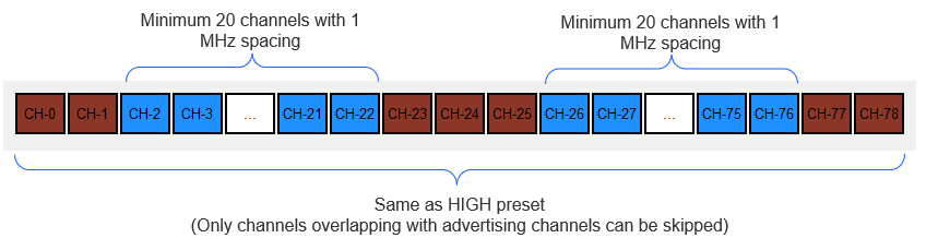
The CS Initiator component uses the sl_rtl_util_validate_bluetooth_cs_channel_map() API to validate a custom channel map. If the requirements are not met, the application closes the connection and terminates with the error code 0x24: CS_ERROR_EVENT_INITIATOR_FAILED_TO_GET_CHANNEL_MAP.
Note that, for RTT, only the CS_CHANNEL_MAP_PRESET_HIGH is currently supported.
Antenna Offset#
For CS development boards (Ex: BRD4198A, BRD2606A), the distance offset caused by the antenna group delay is already calibrated and configured in the initiator and reflector sample applications.
For custom boards, the default values in SL_RAIL_UTIL_CS_ANTENNA_OFFSET_WIRELESS_CM macro are set to 0. The antenna offset(s) must be determined for each antenna by following the wireless distance calibration procedure as described in Section 4 of AN1493. It can then be configured in config/sl_rail_util_cs_antenna_offset_config.h or via the RAIL Utility, CS Antenna Offset component under Platform > Radio in the Software Component Editor.
// SL_RAIL_UTIL_CS_ANTENNA_OFFSET_WIRELESS_CM - antenna wireless offset array in centimeters (-32768..32767)
// If fewer than 4 antenna paths are available, 0 must be supplied for the non-existent elements.
// Example calibrated (board) values were: { 56, 67, 0, 0 }
#define SL_RAIL_UTIL_CS_ANTENNA_OFFSET_WIRELESS_CM { 0, 0, 0, 0 }Antenna Configuration#
CS Tone#
The Antenna Configuration Index (ACI) during CS tone exchanges, as described in Fundamentals, is configured by the initiator. The supported ACI values depend on the number of antennas on the initiator and reflector devices.
For custom board designs based on EFR32xG24 SoC where ACI values 2, 3, 5, and 6 can be supported and there are two antenna select GPIO pins, they should be on the same port. This allows switching both GPIOs in a single LDMA instruction, and thus enables the lowest possible antenna switching time (t_sw) value.
The GPIO(s) for antenna switching is configured in the RAIL Utility, AoX component found under Platform -> Radio in the Component Editor.
CS SYNC#
For devices with multiple antennas, the antenna configuration can be modified to choose the antenna for CS SYNC packet reception. By default, the CS sync antenna configuration is set to CS_SYNC_SWITCHING where the device cycles through the available antennas in a repetitive order from 0x01 to 0x04. On the initiator, it can be changed in the config/cs_initiator_config.h file or in the CS Initiator component. On the reflector, it can be changed in the config/cs_reflector_config.h file or in the CS Reflector component.
CS Procedure Scheduling#
In free-running mode, the CS procedure schedule is determined by the connection interval and the procedure interval. There are two preset configurations for scheduling the CS procedures where the connection interval and CS procedure interval values are chosen to either optimize CS update frequency or energy consumption. By default, the CS procedures are scheduled to achieve the optimal CS update frequency for the configured algorithm mode and number of antenna paths.
The optimized CS procedure values of different initiator configurations for a single reflector connection are defined in cs_initiator_client.c. When CS submode is enabled, a calculated offset is added to the procedure interval based on the connection interval.
When custom procedure scheduling is used, the connection interval and procedure interval configured in config/cs_initiator_config.h are used to schedule the CS procedures. The values are ignored otherwise.
CS Procedure Interval#
The procedure interval is defined as the number of connection events between consecutive measurement procedures. It is a crucial parameter as it determines the CS sample frequency (f_cs):
f_cs = 1/(connection_interval * procedure_interval)
Example: connection interval = 20 ms, procedure interval = 15 → f_cs = 1 / (0.020 s * 15) ≈ 3.33 Hz.
When reducing the procedure interval, keep in mind that the interval must also accommodate enough time for the initiator to complete distance calculations. Increasing the number of antenna paths, channels, or adding a sub-mode will result in more data, thereby requiring a longer procedure interval.
The CS procedure interval is configured to 38 by default for a minimum connection interval to achieve stable measurements in the following worst‑case single‑reflector configuration:
PBR main mode with RTT submode
SL_RTL_CS_ALGO_MODE_REAL_TIME_BASICCS_ANTENNA_CONFIG_INDEX_DUAL_ONLYCS_CHANNEL_MAP_PRESET_HIGH
CS Maximum Procedure Count#
This defines the maximum number of CS procedures to be scheduled. If set to 0, the CS procedure continues in free-running mode until explicitly stopped. If set to 1, the procedure will stop after running once, after which it is restarted by the application. Keep in mind that restarting the CS procedure, consumes 9 connection intervals, and will therefore result in slower sample frequencies.
Note that the max and min CS procedure intervals are ignored if the maximum procedure count is set to 1. In this case, the procedure interval is limited by the time it takes to restart the procedure. Restarting a procedure consumes 9 connection intervals. CS_REQ, CS_RSP, CS_IND consume 2, after which the devices have 7 intervals to prepare for the procedure.
Multi-Connection CS#
The sample applications are optimized to achieve low latency in a 1:1 initiator<->reflector setup where a single initiator is connected to a single reflector. To enable multiple simultaneous reflector connections with minimal procedure aborts, the CS procedure interval must be increased from its optimized single-connection interval value. The procedure interval can be increased by a multiple of the number of active connections.
Example scenario: Consider 3 reflector connections with a single initiator, medium channel map, real-time basic, 4 antenna paths, and PBR main mode as the initiator configuration. In this case, the frequency optimized CS procedure interval is 13 (from cs_initiator_client.c) for a connection interval of 7 (8.75 ms).
For 3 CS connections, the CS_INITIATOR_DEFAULT_MIN_PROCEDURE_INTERVAL and CS_INITIATOR_DEFAULT_MAX_PROCEDURE_INTERVAL should be set to 3*13 = 39.
Alternatively, the connection interval can be adjusted to increase the procedure interval, which can qhelp reduce power consumption on the reflector.
CS TX Power#
The reference board supports a maximum TX power of 10 dBm. This value can be changed in the config/cs_initiator_config.h file.
// CS_INITIATOR_DEFAULT_MAX_TX_POWER (dBm) - Default: 10
#define CS_INITIATOR_DEFAULT_MAX_TX_POWER 10