Real-Time Location (RTL) Library#
Overview#
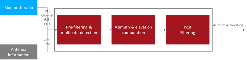
Estimating the Angle of Arrival (AoA) or Angle of Departure (AoD) from IQ samples is not trivial, especially in a real environment full of reflections. To ease the burden for developers and to speed up time-to-market, Silicon Labs provides a Real Time Locating library (RTL lib), which processes the IQ samples received from the Bluetooth stack, implements multipath detection and azimuth and elevation calculation, and exposes the data to the application via an open API.
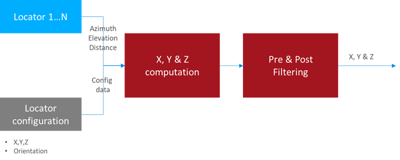
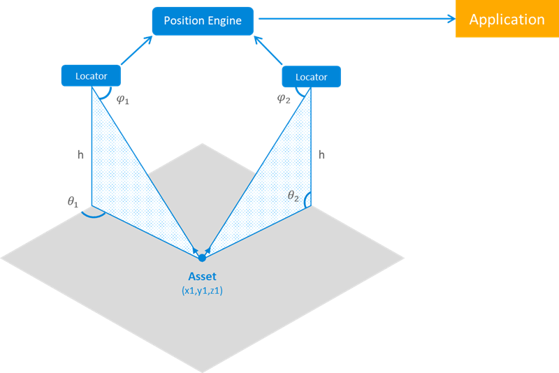
Furthermore, the library is also able to estimate the location of a tracked asset in a multi-locator scenario using triangulation, where multiple locators receive CTEs from the same asset tag, provided that the library knows the position of each locator. In this case the positions of the locators and the estimated angles (AoA) serve as the input, and the estimated location is the output.
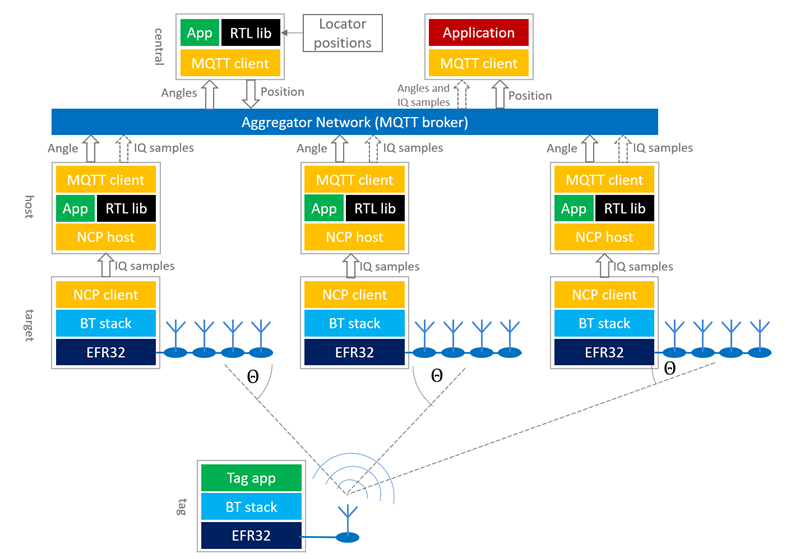
Once the positions are estimated it is up to the user’s application how to process the data. The general architecture of an RTLS using Silicon Labs RTL library looks like this:
All AoA-related sample apps in the Bluetooth SDK are created so that they support this model. To learn more about the sample apps, see Application Development with Silicon Labs’ RTL Library.
Note that on the Locator side the devices work in a Network Co-Processor (NCP) mode, that is, the stack runs on the EFR32 chip, but the application runs on a host computer. Currently, due to the limited computational capacity of the EFR32 chips, only NCP mode is supported, that is the RTL library cannot be used on the chip. To learn more about NCP mode, see Using the v3.x Silicon Labs Bluetooth® Stack in Network Co-Processor Mode.
The locators can connect to the central PC in many ways. Silicon Labs’ reference implementation uses MQTT to collect angle data from locators, since it gives the flexibility to run the host sample apps on a distributed network as well as on a single PC using localhost, but other implementations can be used as well.
The RTL library provides the following features:
Feature | Value and Comments |
|---|---|
Direction Finding Method | AoA |
# of tags supported | infinite (lib needs to be initialized for each, and physical channel puts a limitation on this) |
# of locators supported | infinite (lib needs to be initialized for each) |
Antenna arrays supported | BG22 Dual Polarized Antenna Array Radio Board (BRD4191A), EFR32BG22 Direction Finding Radio Board (BRD4185A), CoreHW PCB4 and PCB8 Antenna Array boards |
Modes of operation | Single shot / Real time, Fast response / Basic / High accuracy Azimuth & elevation / Azimuth only |
Supported platforms | Windows x64, Ubuntu x64, Raspbian (Cortex A), Darwin x64 |
The RTL library is provided as a single static library for each supported platform. The library can be found in the Gecko SDK suite under:
GSDK 3.x: C:|SiliconLabs|SimplicityStudio|v5|developer|sdks|gecko_sdk_suite|v3.1|util|silicon_labs|aox
GSDK 4.0 and higher: C:|Users|<username>|SimplicityStudio|SDKs|gecko_sdk|util|silicon_labs|aox
The library has three API classes:
Angle of Arrival / Departure (sl_rtl_aox_): API used for AoA/AoD estimation from IQ samples. (Currently only AoA is supported.)
Location Finding (sl_rtl_loc_): API used for location estimation (x, y, z coordinates) from AoA/AoD.
Utility Functionality (sl_rtl_util_): API grouping utility functions that may be useful during AoA/AoD/location estimation
Inside the Angle of Arrival / Departure and Utility Functionality classes an IQ Sample Quality Analysis API is also available to provide analytical measurements of different kind of errors in the system.
Angle of Arrival / Departure#
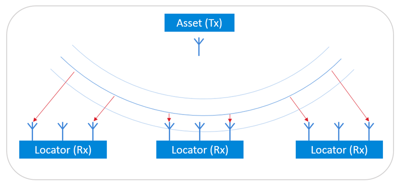
There are two Bluetooth based direction-finding methods: Angle of Arrival (AoA) estimation and Angle of Departure (AoD) estimation. Currently the RTL library supports AoA mode only. In this mode, the transmitter transmits a constant tone on a single antenna, and the receiver receives this signal on multiple antennas. Based on their spatial situation, the receiver antennas will receive the same signal with different phase offsets, from which the direction of the incoming signal can be estimated.
While it is easy to estimate the Angle of Arrival in an environment free of noise and reflections, it can get quite challenging in a noisy real-world environment with a lot of reflections. To mitigate the effects of reflections, the RTL library uses different methods, such as spatial and temporal filtering, averaging over multiple frequencies, and so on.
Antenna Configuration#
The estimator algorithm must know the exact position of each antenna in the array, and the phase of the incoming signal for each antenna. Currently the RTL library only supports some antenna array boards with pre-defined antenna positions. When running the RTL library, the antenna array board must be specified so that the library knows which predefined values to use. Custom antenna array configuration is not yet available. The default antenna array board set in the sample applications is BRD4191A.
Angle Estimation Modes#
The library provides different modes for different use cases:
One Shot / Real Time modes
In “one shot” mode the angles are always calculated from the latest measurements without any a priori knowledge or assumptions about the direction of the transmitter. On the other hand, in the “real time” mode the library keeps account of the latest angle estimation and tries to find the transmitter in the vicinity of the last direction.
Fast Response / Basic / High Accuracy modes:
In “fast response” mode the estimator uses fewer measurements to provide one estimation. This results in a fast response but can result in a poor accuracy. On the contrary, “high accuracy” mode uses more measurements, which results in higher latency, but much better accuracy. Basic mode is a trade-off between fast response and high accuracy. For details see the RTL API Reference.
Azimuth & Elevation / Azimuth Only modes:
By default the RTL library calculates both azimuth and elevation angles. In some use cases, however, it is enough to calculate the azimuth angle. “Azimuth only” mode results in faster calculation.
These modes are used together to give a single AoA mode that can be set when initializing the library. For details see the RTL API Reference.
Location Finding (Positioning)#
If there are multiple fixed-position locators that can calculate the direction of the transmitter (asset tag), the position of the asset tag can be calculated from the angles using triangulation. Beside Angle of Arrival estimation the RTL library also provides location finding functionality. Once the library learns the position of and gathers the angles from each locator it can provide a position estimation for asset tags. Just as for AoA estimation, challenges introduced by the reflective and noisy environment are addressed.
Locator Configuration#
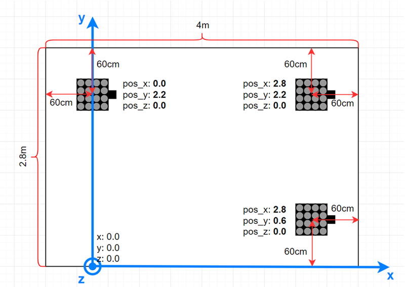
In order to calculate the position of the asset tags (transmitters), the RTL library must learn both the position and the orientation of each locator relative to a local coordinate system. The choice of the local coordinate system is arbitrary, the only constraint being that it must be right-handed Cartesian (so that if x is pointing right, y is pointing up, as on the following image), and the unit of distance must be meter. The position of each locator board must be understood as the position of the center of the antenna array – relative to the origin.
The position and orientation of each locator can be provided to the RTL library using the RTL API, but the bt_host_positioning sample app also makes it possible to describe the configuration of each locator in a single config file using JSON format. For more details see Application Development with Silicon Labs’ RTL Library and Using the Bluetooth® Direction Finding Tool Suite.
Location Finding Modes#
The RTL library supports two location-finding modes: two-dimensional and three-dimensional. In three-dimensional mode x, y and z coordinates of the tag are calculated from the azimuth and elevation angles. In two-dimensional mode, the z coordinate of the tag is fixed (this fixed value must be provided to the library using the RTL API sl_rtl_loc_set_target_parameter) and x and y coordinates are calculated.
IQ Sample Quality Analysis#
Errors from multiple sources can affect the quality of the received IQ samples. In a real-life environment, some phenomena are considered as normal and not errors, but can also corrupt the perceived IQ data. The most notable example of this is the multipath propagation, which twists the perceived magnitude and phase of the IQ sample data. Its extent depends on the particular antenna location in the array as well as the position and the angle of the followed tag related to the locator antenna array.
The possible sources for the perceived noise may include the following:
Radio receiver analog noise
Quantization noise from the sampling
Leaking signals from the surrounding channels folding into the band of interest
Sampling jitter that translates into noise
Other radio protocols operating on the same band
Cosmic background noise
In other words, there are a plenty of sources for signal noise even in relatively good conditions.
As well as the calculation of Angle of Arrival and position estimations, the RTL library also provides functionality called IQ sample quality analysis to help the developer find the root cause of angle estimation issues by analyzing statistical properties of the IQ samples.
Description of Operation#
The IQ sample quality analysis tool may be used to further investigate what could be the source of observed problems in the AoA/AoD angle values. If the calculated angles seem to be good and the position values calculated from these are within the expected range, investigating the quality analysis figures may not be of use.
The IQ sample quality analysis measures a few statistical key figures from the samples and presents them per antenna element level. These include:
Antenna’s signal level (in dB), average over snapshots in the same radio packet
Antenna’s signal to noise ratio (SNR), noise measured as a level variation between antenna’s samples in the packet
Phase value: antenna’s unrotated average phase value, in radians (relative to the delay between antenna elements in the array)
Phase jitter: antenna’s unrotated phase variation, in radians
A few common, or not antenna related, values are included for a packet:
The radio channel the packet was sent on
Apparent supplemental tone frequency, in Hz
Reference period signal to noise and distortion ratio (SNDR)
If enabled, the IQ sample quality analysis code detects some predefined conditions and raises a warning flag for each in case the limits were exceeded. These limits are defined inside the RTL library and are subject to change without further notice. The limits are chosen such that warning flags should not be raised in normal conditions but only occasionally. However, since every environment is different the actual number of warnings may vary from system to system. These flags are shown to the user as bits in a bitmask output of the overall status query function. Further information can be then queried using the detail query functions. The API allows querying details for the latest packet received, or for the latest packet using a specified radio channel.
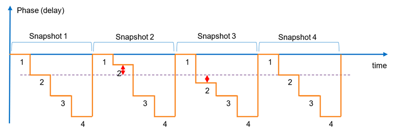
The following figure shows an example phase signal of a 1 x 4 antenna array. The signal is otherwise ideal, but some exaggerated error is seen in the detected phase (=delay) values for the second antenna in the array during the snapshots 2 and 3. The amplitude graph also resembles a step function, but unlike the phase signal, the amplitude value does not change the same way along the angle the signal is arriving on. In real life the change from an antenna to next does not take place immediately but there is a transfer period during which the signal settles. This is affected by the radio system and filtering.
Some Interpretation Examples#
Here are some practical examples of what can be learned from the quality figures in different situations:
The figures seem mostly good, but some channels have a high amount of noise.
→ These radio channels may be occupied by some other system.
Some antennas show much lower amplitude levels. The amount of reduction, and also the antennas on which this is seen, changes along the position of the followed tag.
→ Radio signal reflects from the surfaces of the surrounding space causing interference with the received signal (called multipath propagation).
Some antenna values show a lot of noise or the phase value is not changing relative to the tag movement as it does for other antennas
→ The antenna board may be defective, preventing it from receiving the signal from one or more antennas.
All the antennas’ phase values are the same
→ The tag is directly above the antenna board at a 90° elevation angle.
→ Symbol The antenna board may be defective and is not switching at all.
Reference period SNDR value is bad
→ The whole packet may be corrupted because of some other system’s disturbance.
Usage#
The IQ sample quality analysis tool is available through the Angle of Arrival/Departure API class of the RTL lib. See the functions starting with sl_rtl_aox_iq_sample_qa_ in the API Reference. For a reference implementation of the usage of IQ sample quality analysis see the aoa_locator host sample app in the Bluetooth SDK.