Positioning Sample Application#
A single antenna array can give a rough estimation of the position of an asset, given that the distance can be determined from the RSSI or is constrained. However, to determine the location of an asset tag with high accuracy multiple locators are needed. Each of the locators can determine the Angle-of-Arrival of the asset, from which the position of the asset tag can be calculated using triangulation.
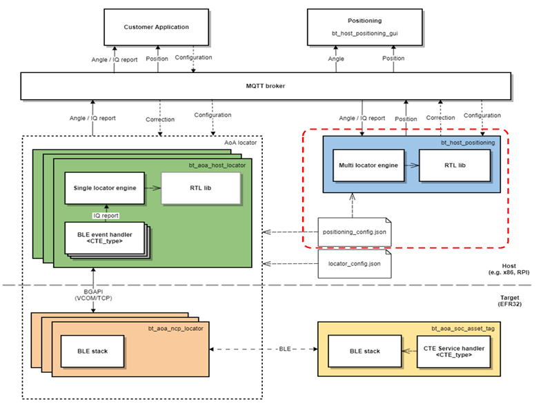
The Bluetooth SDK v3.x provides a unified positioning host application (example_host/bt_host_positioning) to demonstrate direction finding using multiple locators.
The positioning host application must:
Parse a JSON configuration file containing the IDs, orientation, and coordinates of each individual locators.
Initialize an MQTT client and subscribe to topics created by each locator.
Upon arrival of MQTT messages:
feed the IQ reports to the RTL library (optional).
feed the angle objects to the RTL library.
Get the position (x, y, z) of the tag and publish it to the MQTT broker.
Publish “correction” feedback MQTT messages about the expected angles.
Subscribe to configuration topic.
These are all done in the app.c file of the example_host/bt_host_positioning project. Note that the angle data is agnostic to the type of the CTE transmission mode used. This offers great flexibility and possibilities to have different locator types in the same infrastructure. From the positioning host perspective, ideally, a tag can send CTEs for two different locator types (for instance, connection-based locator and Silicon Labs proprietary locator), and the angle data coming from both can be used to estimate the position of the tag accurately.
Like the single locator case, where the NCP AoA locator and AoA locator host can be decoupled in space, the positioning host also does not necessarily need to run on the same machine. It can basically run on any machine, a PC or Cloud (example AWS EC2). In fact, the positioning host does not need to know the IP addresses of each locator, as the communication takes place using the MQTT protocol. The MQTT publish/subscribe communication model provides great flexibility and has none of the disadvantages inherent to the client/server architecture.
However, to locate a tag, the positioning host application needs to know the IDs of each locator, their positions relative to a local coordinate system, and orientations with respect to the X, Y, and Z axes.
Positioning Configuration#
The positioning configuration file has a simple JSON format that has name/value pairs of location configuration parameters, and a group of JSON objects containing name/value pairs of each individual locator’s configuration parameters. A prototype of the positioning configuration file is shown below. A complete config file can be found inside example_host/positioning /config folder.
{
"version": 1,
"id":"positioning-test_room",
"estimationModeLocation":"SL_RTL_LOC_ESTIMATION_MODE_THREE_DIM_HIGH_ACCURACY",
"validationModeLocation":"SL_RTL_LOC_MEASUREMENT_VALIDATION_MEDIUM",
"estimationIntervalSec":0.02,
"locationFiltering":true,
"locationFilteringWeight":0.1,
"numberOfSequenceIds":6,
"maximumSequenceIdDiffs":20,
"locators":[
{
"id":"ble-pd-111111111111,
"config": {Place for first locator configuration. See AoA Locator Configuration.
},
"coordinate": {
"x":0.0,
"y":0.0,
"z":0.0
},
"orientation":{
"x":0.0,
"y":0.0,
"z":0.0
}
},
{
"id":"ble-pd-22222222222,
"config": {Place for second locator configuration. See AoA Locator Configuration.
},
"coordinate":{
"x":0.0,
"y":0.0,
"z":0.0
},
"orientation":{
"x":0.0,
"y":0.0,
"z":0.0
}
}
]
}The configuration file contains the whole AoA configurations used by the positioning and single AoA locator host examples. Thus, when running the positioning example, the single AoA locator hosts can use the same config file: app/bluetooth/example_host/bt_host_positioning/config/positioning_config.json. In this case, each AoA locator host collects and parses the “config” JSON object that is related to it by searching for its ID.
The positioning configuration can also be defined with the visual tools AoA Configurator and Positioning Tool, provided with Simplicity Studio. AoA Configurator defines the topology of the multi-locator setup (coordinates and orientation of each locator), while the purpose of the Positioning Tool is twofold:
It can create a top-level configuration file that defines top level settings and assigns the locators with a topology and with locator configurations.
It can consume the top-level configuration, connect to each listed locator, and run the RTL library to estimate positions from the incoming data (without the need of running any host sample application).
To learn more about AoA Configurator and the Positioning Tool, refer to Using the Bluetooth Direction Finding Tool Suite. Note that the topology file, the top level configuration file, and the locator configuration files created by the tools must be exported to be compatible with the host applications, as described in the same document.
Positioning ID#
The positioning ID can be any string used to identify your setup, example “positioning-test_room”.
Location Parameters#
The location parameters, including estimation model, estimation interval, etc, override the default values of the corresponding configuration parameters defined in app|bluetooth|common_host|aoa_loc|aoa_loc.c.
To estimate the position of an asset tag accurately, the positioning engine must also know the IDs of each locator, their positions relative to a local coordinate system, and their orientations with respect to the X, Y, and Z axes as explained in the following subsections.
Locator IDs#
The IDs of the locators are generated from their Bluetooth address and are formed as ble-<ADDRESS_TYPE>-<BLE_ADDRESS>, where <ADDRESS_TYPE> is either sr (for static random) or pd (for public device). <BLE_ADDRESS> is the 6-byte address without any separators, strictly using UPPERCASE letters.
The Bluetooth address of the locator can be learned in many ways. One way is to start the bt_aoa_host_locator sample app, which logs the Bluetooth address of the locator at the beginning.
Locator Coordinates#
The coordinates are relative to a local coordinate system. The origin of the coordinate system and the orientation of the coordinate system are arbitrary. The only constraint is that it must be right-handed Cartesian (so that if x is pointing right, y is pointing up, as in the following image), and the unit of distance must be meter. The position of each locator board must be understood as the position of the center of the antenna array relative to the origin.
It is recommended to mount the antenna arrays 1m away from walls and any other blocking objects. The following image provides an example how the positions of the boards must be given (each board is assumed to be at the same height, z=0):
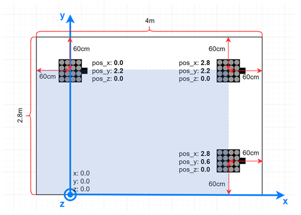
The coordinate configurations for the above setup looks like this:
{
"id": "positioning-test_room",
"locators": [
{
"id": "ble-sr-111111111111",
"coordinate": {
"x": 0.0,
"y": 2.2,
"z": 0.0
}
},
{
"id": "ble-pd-222222222222",
"coordinate": {
"x": 2.8,
"y": 2.2,
"z": 0.0
}
},
{
"id": "ble-pd-333333333333",
"coordinate": {
"x": 2.8,
"y": 0.6,
"z": 0.0
}
}
]
}Locator Orientations#
After defining the coordinates of the locator boards, it is also very important to define their orientation (rotation). The calculated Angle of Arrival is always relative to the coordinate system of the board, not to the local coordinate system. Therefore, the orientation of the boards must be known, so that the RTL library can transform the angles to align with the local coordinate system.
Defining the orientation of the locators may sometimes get quite complicated, because the rotations are defined in the local coordinate system of the board, which is also rotated together with the board. Therefore, it is highly recommended to set the orientation of each board with the 3D tool, AoA Configurator. This tool provides instant feedback about how the boards are oriented in 3D for the given rotation angles, and misbehavior caused by wrong configuration can be avoided. To learn more about the AoA Configurator tool, refer to Using the Bluetooth Direction Finding Tool Suite. Note that the topology file created by the tool must be exported to be compatible with the host applications, as described in the same document.
If instead you want to define the orientations manually, information is provided in the rest of this section.
The coordinate system of the locator board looks like this:
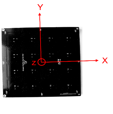
If the board is positioned so that the axes of this coordinate system are parallel to the axes of the local coordinate system, the rotation (orientation) does not need to be defined. In any other case, the orientation relative to this default state must be defined. (Note that in the previous image, the patch antennas are facing upward, the z axis is also pointing upward, and the x axis is pointing to the 0° direction as marked on the board.)
The orientation of the board is defined by three values: x, y, and z. Here x means that the board is rotated around the X axis by x degrees. Similarly, y and z mean that the board is rotated around the Y / Z axis by y / z degrees. Positive values mean that the board is rotated to the positive direction, that is counterclockwise, when the given axis is pointing towards you. The center of the antenna array board should stay at the same point while rotating.
The following image gives a very simple example of how the orientation should be defined. Here two boards are rotated around the z axis by 90°and -90°. (Note that patch antennas of the boards are facing upward.)
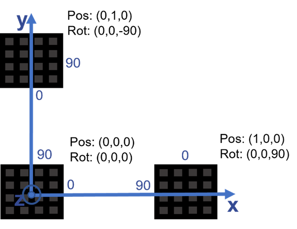
In this case, the configuration file should look like this:
{
"id": "positioning_test_room",
"locators": [
{
"id": "ble-sr-111111111111",
"orientation": {
"x": 0.0,
"y": 0.0,
"z": 0.0
}
},
{
"id": "ble-pd-222222222222",
"orientation": {
"x": 0.0,
"y": 0.0,
"z": 90.0
}
},
{
"id": "ble-pd-333333333333",
"orientation": {
"x": 0.0,
"y": 0.0,
"z": -90.0
}
}
]
}It may easily happen that the board must be rotated around multiple axes to get from the default orientation to its actual orientation. In this case it is important to consider that:
The rotations must be done in Z – Y – X order while proceeding from the default orientation to the actual orientation.
The axes are also rotated with the board, so at the 2nd rotation the new state of axes must be considered.
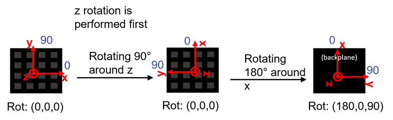
The following images give some examples for this scenario. Assume the board is facing upside down, and its 0° direction is pointing in the direction of the y axis of the local coordinate system. To get this orientation from the default orientation, the board has to be rotated 90° around its z axis first, then 180° around its x axis:
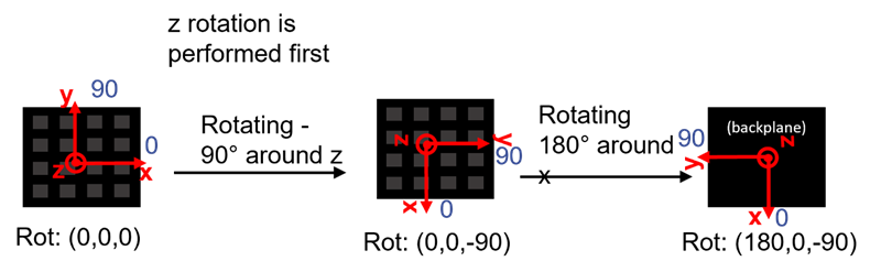
Similarly, if the board is facing upside down, and its 0° direction is pointing in the opposite direction as the y axis of the local coordinate system, then the board has to be rotated -90° around its z axis first, then 180° around its x axis:
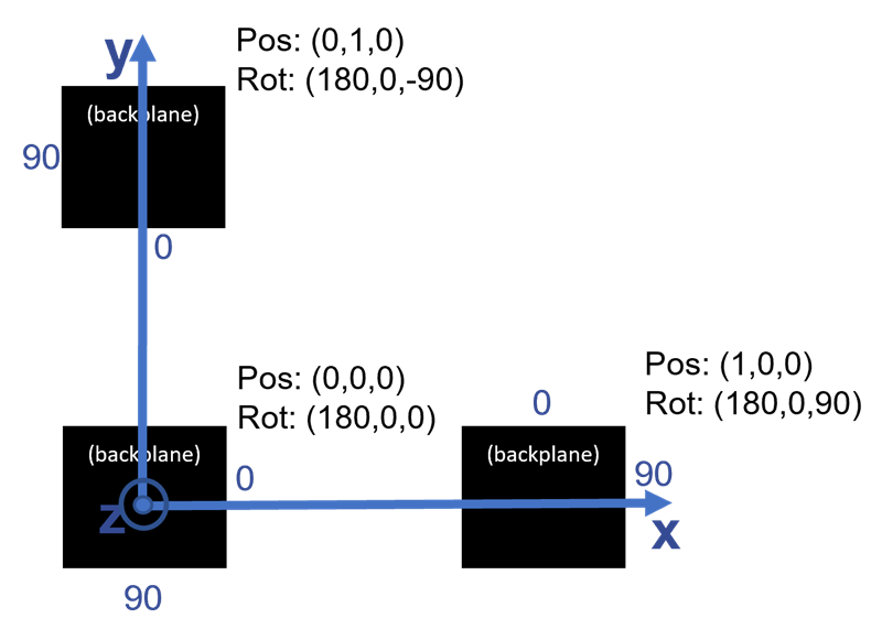
The following image gives a simple example of how the orientation should be defined for a system with antenna arrays facing down:
The following two images show two recommended setups for testing purposes.
(a) 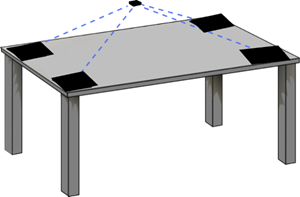
The simplest setup (a) is when four locators are placed on the four corners of a table, facing up. In this case the tag should be located above the plane of the table, since the antenna arrays “see” only upward. If the locators are rotated to the same direction, then all orientation parameters will be 0 in the config file.
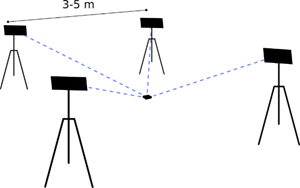
A slightly more realistic use case is the second case (b), when the antennas are either fixed on the ceiling or standing on tripods, facing down. This ensures a better line of sight in any room. The recommended distance between the antennas is 3-5 m. In this case the tag should be found under the antenna array, and since the antenna arrays are facing down, the orientation parameter for either x or y of each of them should be set to 180° in the config file.
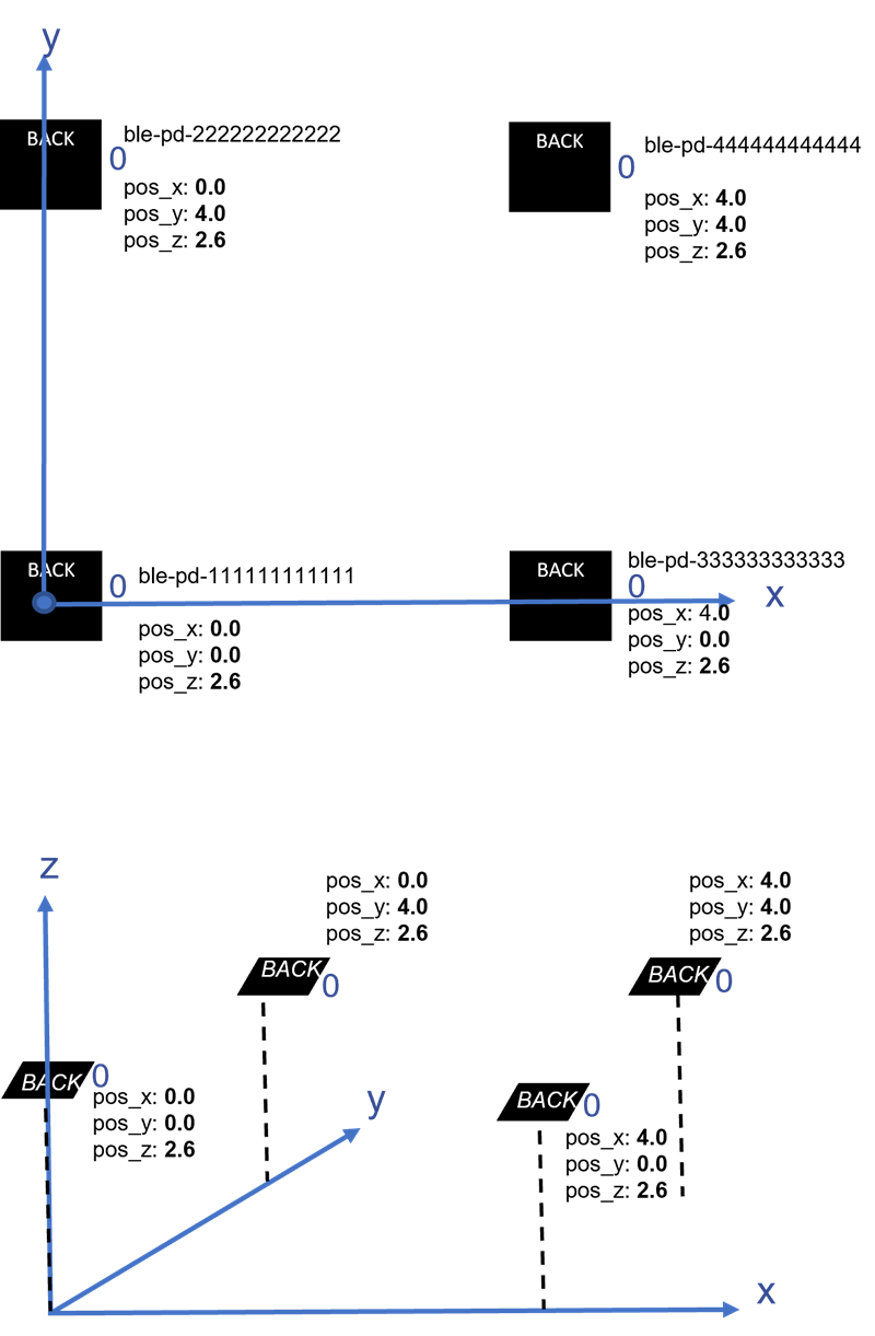
The following configuration shows a practical setup for the above scenario. The setup consists of four locators which are in square formation at a height of 2+ meters, rotated upside-down. The locators can be, for example, mounted onto the ceiling or on stands. The evaluation setup has four locators to provide best possible positioning and ensure that effects of multipath are minimal in the position calculation, as most often at least three of the locators give correct angle estimations.
{
"id": "positioning_evaluation_setup",
"locators": [
{
"id": "ble-pd-111111111111",
"coordinate": {
"x": 0.0,
"y": 0.0,
"z": 2.6
},
"orientation": {
"x": 180.0,
"y": 0.0,
"z": 0.0
}
},
{
"id": "ble-pd-222222222222",
"coordinate": {
"x": 0.0,
"y": 4.0,
"z": 2.6
},
"orientation": {
"x": 180.0,
"y": 0.0,
"z": 0.0
}
},
{
"id": "ble-pd-333333333333",
"coordinate": {
"x": 4.0,
"y": 0.0,
"z": 2.6
},
"orientation": {
"x": 180.0,
"y": 0.0,
"z": 0.0
}
},
{
"id": "ble-pd-444444444444",
"coordinate": {
"x": 4.0,
"y": 4.0,
"z": 2.6
},
"orientation": {
"x": 180.0,
"y": 0.0,
"z": 0.0
}
},
]
}Updating AoA Configuration Through MQTT#
The whole configuration file or specific configuration parameters of the positioning and/or AoA locator host applications can be updated through MQTT on the fly without rebuilding and rerunning the applications. This is done by publishing the configuration update with the specific config topic that the broker can use to forward the message to interested subscribers.
The Positioning host subscribes to two configuration topics, which can be used to update configuration changes during runtime. The formats of these topics are:
silabs/aoa/config/<positioning_id>silabs/aoa/config
In summary, when running a multi-locator setup, the following configuration topics can be used to update the configuration of the locators and position hosts on the fly.
AoA locator:
silabs/aoa/config/<locator_id>Positioning:
silabs/aoa/config/<positioning_id>AoA locator and/or Positioning: silabs/aoa/config
The first two topics can be used when updating the configuration of a specific locator with a given <locator_id> ID and the positioning host identified with <positioning_id> ID, respectively. The third topic is a universal configuration topic which can be used for updating the configuration of one or more locators, and/or the positioning host at a time. In this case, it is possible to make all the configuration changes in one place (for example, inside the positioning_config.json file), copy the content and push that via MQTT to make all the configuration updates simultaneously.
Running the Positioning Sample App#
After the project is built, an executable file bt_host_positioning.exe is generated inside the exe folder. Run the application using the following command:
bt_host_positioning.exe -c <config> [-m <address>[:<port>]] [-n]Options:
-c positioning configuration file. It contains the positioning configuration parameters.
<config>: Path to the configuration file. An example config file is provided in bt_host_positioning/config/positioning_config.json.
-n Turn off the bad angle feedback feature. Default is on.
The positioning host can be started with/without the configuration option. However, to calculate position of the tags, the application requires the configuration of the locators which can be passed via MQTT during runtime as explained in Updating AoA Configuration Through MQTT.
Regardless of the individual locators’ types and their configuration, the positioning host application provides a common interface for the position data structure of the tag/s to the MQTT broker. A prototype of the position data looks like:
{
"x": 1.509856,
"x_stdev": 0.321395,
"y": 0.329126,
"y_stdev": 0.309377,
"z": 1.650664,
"z_stdev": 0.218991,
"sequence": 29076
}To test the positioning host application
Flash a tag device (such as a Thunderboard BG22) with a bootloader and the asset tag sample project of your choice as described in Bluetooth AoA- SoC Asset Tag.
Flash one or more NCP AoA locator boards with the antenna arrays attached to WSTKs (such as BRD4191A) with a bootloader and the NCP AoA locator as described in NCP AoA Locator Sample Application.
Make sure you have the correct build environment: Building the Single AoA Locator Host Sample Application.
Make sure you have installed Mosquitto MQTT broker: Prerequisites.
Attach the WSTKs to the PC either by USB or Ethernet.
Open the export/app/bluetooth/example_host/bt_aoa_host_locator/exe folder and start the host application for each locator with their USB COM or IP address, for example
.\bt_aoa_host_locator.exe -u COM57. Each locator can be started with or without a config file..\bt_aoa_host_locator.exe -u COM57 -c ../config/locatorX_config.json | $GSDK_DIR/app/bluetooth/example_host/bt_host_positioning/config/positioning_config.jsonEach locator host must run simultaneously, so you will need more command prompts if you are running all the host applications on the same PC. For more accurate results, use at least four locators in your setup.
Navigate to the /app/bluetooth/example_host/bt_host_positioning folder.
Open Mintty bash and build the project by executing make.
Find the default positioning configuration file under /app/bluetooth/example_host/bt_host_positioning/config/positioning_config.json and modify it according to the IDs, coordinates, and orientations of your locators.
Start the positioning host application from a command line with the config file as parameter, for example:
.\exe\bt_host_positioning.exe -c .\config\positioning_config.jsonIf the MQTT broker is not using the default host:port parameters, configure it with the
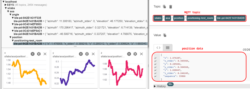
-moption:-m <address>:<port>.Open the MQTT Explorer to monitor the angle and position data. You should see something like the following.
Now, try updating the configuration of either the positioning or one of your locators by modifying any config parameters you want to see take effect. You can do so easily using the MQTT Explorer “Publish” window. For example, change the location estimation mode to SL_RTL_LOC_ESTIMATION_MODE_THREE_DIM_FAST_RESPONSE in the positioning_config.json, copy and paste the content of the file into the MQTT Explorer, and publish it using the
silabs/aoa/config/<positioning_id>topic.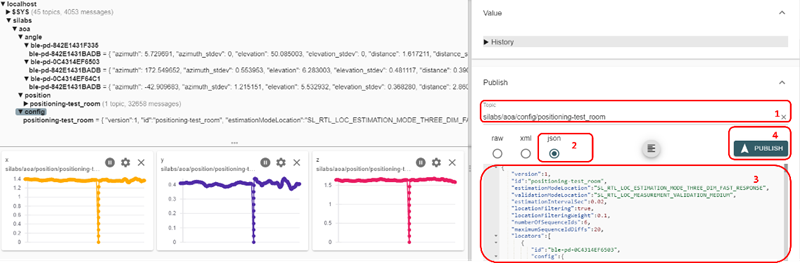
Note that each CTE packet contains a 16-bit event counter. The positioning host application uses this value to calculate the positions of an asset tag by matching IQ samples with similar event counter. In connection mode, however, since event counters for different connections are different, the positioning host will not give any results. Thus, the connection mode should not be used to test the positioning application.
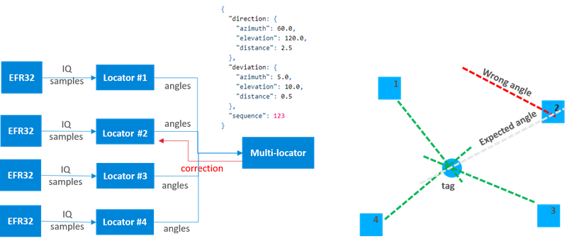
By default, the positioning application runs with a feedback mechanism enabled. The feedback mechanism provides a “correction” for a deviating locator whose angle reports are far off the expected one, and thus is not pointing to the same direction where all other locators see the tag. The correction feedback provides the single locator with the information in which direction it is supposed to see the tag. This helps locators that locked up on a reflection signal which is stronger than the one coming in the line-of sight direction. The feedback mechanism works with four or more locators in a setup.
If you want to run the application without the feedback mechanism, start the positioning application on the command line with the -n flag:
.\exe\bt_host_positioning.exe -c .\config\positioning_config.json -nThe positioning application does not print logs to the console. This was opted out intentionally to avoid the overhead of printf which can cause significant delay, especially if there are several tags updating angle and position information to multiple locators.
When tracking more than one tag, it is important to increase the CTE advertising interval from the default value (which is 20 ms) to at least 100 ms as shown below to prevent the locators’ UART from being congested, and more importantly avoid packet collisions. In this case, the estimation interval of the positioning application in app_config.h should also be changed accordingly.
// Estimation interval in seconds.
// This value should approximate the time interval between two consecutive CTEs
#define ESTIMATION_INTERVAL_SEC 0.1f // changed from default value 0.02fVisualization Script for Silicon Labs Positioning Sample Application#
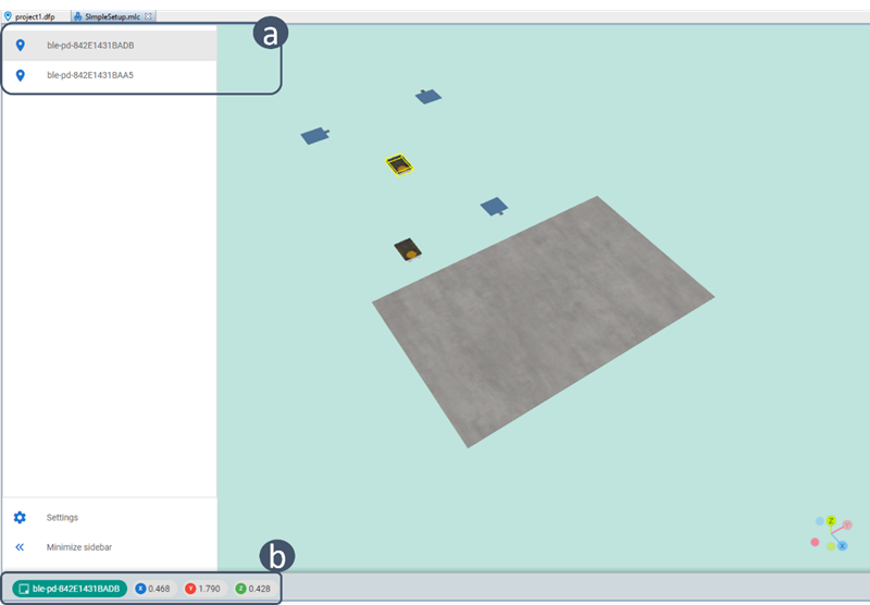
The Bluetooth SDK also provides a script to visualize the results of the positioning application. The visualization script is a separate Python application that collects position data by subscribing to the topics that the positioning sample app publishes to the MQTT broker. Therefore, it is also an example of the user application depicted in the figure at the beginning of this page.
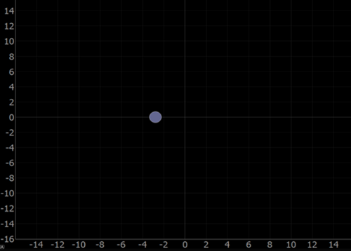
The images below show how the 2D and 3D modes should look in the visualization.
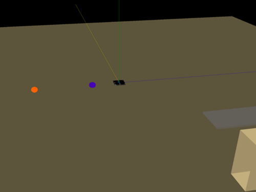
The 3D view also supports drawing simple 3D objects such as tables and shelves, as seen on the right in the above figure.
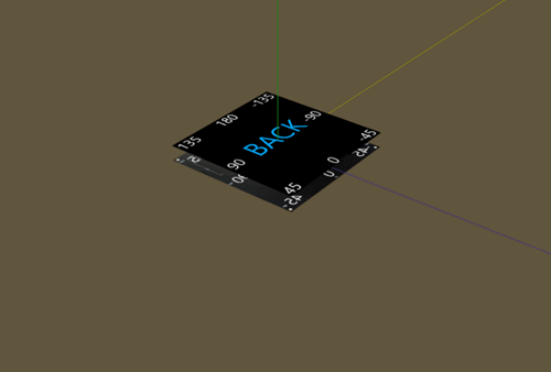
The locators are placed in the environment as given in the locator configuration file, so the visualization can be used to confirm that the configuration file matches the real-world setup. The front of the locator array (the side on which the patch antennas are located) is labeled as FRONT and the back of the locator is labeled BACK.
The visualization script can be found in the Gecko SDK Suite under:
/app/bluetooth/example_host/bt_host_positioning_gui
The following settings are configurable in the visualization script:
PLOT_VIEW_3D (0/1): Toggle 3D view. If disabled, uses 2D view. Note that the 3D view requires more processing and can slow down the tags’ visual update rate. It is suggested to use the 2D mode for better responsiveness and the 3D mode for debugging or better but slower visualization.
PLOT_TAG_ADDRESSES (0/1): Toggle plotting of the tags’ Bluetooth addresses next to their dots.
PLOT_ROOM (0/1): Toggle plotting of objects defined in
plot_room()function in 3D mode.PLOT_DEBUG_LINES (0/1): Toggle plotting visual lines from locators to tags in 3D mode. The number of lines to be drawn can be configured with the parameters MAX_NUM_TAG_LINES and MAX_NUM_LOCATOR_LINES.
PLOT_DEBUG_LOCATORS (0/1): Toggle plotting the locator arrays into the environment in 3D mode. This can be useful to ensure the locator configuration file matches with the actual setup.
PLOT_MARKER_TRACES (0/1): Toggle plotting marker traces. Marker traces are trailing dots that show the previous positions of tags. Number of trace markers to plot at once can be configured by setting self.numMarkerTraces to the desired value.
Setting up the visualization environment
Make sure Python 3.7 is installed in your environment. The version should be exactly 3.7, as Python 2.x or 3.8 will not work.
Install the following packages to your Python 3.7 installation using, for example, pip
py -3.7 -m pip install <package name>orpython3.7 -m pip install <package name>.pyqtgraph
pyqt5==5.14.0 (this exact version for Linux)
pyopengl
numpy
Pillow
paho-mqtt
If the previous package installations fail, try running the follow commands:
python3.7 -m pip install –upgrade pippython3.7 -m pip install –upgrade setuptools
If installation of one of the previous packages cannot be done, the Python visualization may not work properly. Consider running in pipenv or docker in that case.
Running the positioning sample app with visualization
Follow the instructions in section Running the Positioning Sample App to get the positioning app up and running.
Ensure that the Python environment is set up correctly as per the instructions above.
Open a command prompt and navigate to the folder /apps/bluetooth/example_host/bt_host_positioning_gui.
Run the visualization script with either of the following commands:
py -3.7 app.pyor
python3.7 app.pyNote that the visualization script also needs the positioning config file to be able to display the locators and subscribe to the appropriate topics at the MQTT broker. If you do not use the default positioning_config.json file found under /app/buetooth/example_host/positioning/config, then define its location with the
-cswitch as for the positioning sample app:py -3.7 app.py -c ./../bt_host_positioning/config/my_config.jsonSimilarly, if you are not using the default MQTT host:port settings, then define them using the
-mswitch.Now you should be able to see the GUI start, displaying the locators and tags.
Note that 3D mode may have significantly worse performance with more than three locators and more than five tags, and default intervals are used. In this case it is strongly recommended to use the 2D mode or to significantly increase the connection/advertisement intervals.
When tracking more than one tag using multiple locators, it is strongly recommended to disable the debug logs of the host applications, as logging can accumulate latencies and significantly impact the system’s real-time tracking performance. This is particularly evident if the bt_aoa_host_locator and bt_host_positioning applications are running on the same machine.
To disable the logs, open app_log_config.h in <SDK Installation Location>|app|bluetooth|common_host|app_log|config and make the following change:
#define APP_LOG_ENABLE 0Visualization Tool for Positioning#
It is also possible to display the calculated 3D position of each asset tag in Simplicity Studio using the Positioning Tool. The Positioning Tool does not take the results of the positioning sample app, but instead takes the configuration files defined with the AoA tools, connects to each locator, collects IQ samples, calculates angles and finally calculates positions – all in one. The Positioning Tool can be used for evaluation of the RTL library without the need to build host applications. To learn more about the Positioning Tool, see Using the Bluetooth Direction Finding Tool Suite.