Bluetooth Mesh Configurator#
The Bluetooth Mesh Configurator provides access to a Bluetooth Mesh node's Device Composition Data (DCD). This contains information about the elements it includes and the supported models. DCD exposes the node information to a configuration client so that it knows the potential functionalities the node supports and, based on that, can configure the node.
Configuring DCD through the Bluetooth Mesh Configurator is only one part of configuring a Bluetooth Mesh node. For details see UG472: Bluetooth® Mesh Node Configurator User's Guide for SDK v2.x.
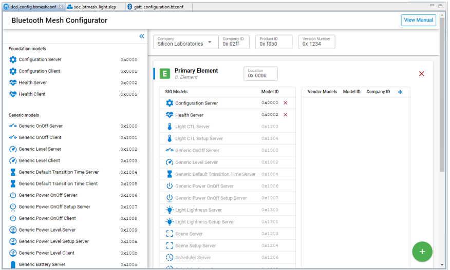
When you create a Bluetooth Mesh project in Simplicity Studio 5, three tabs open automatically: the GATT Configurator (gatt_configuration.btconf), .the slcp or Project Configurator (<projectname>.slcp, and the Bluetooth Mesh Configurator (dcd_config.btmeshconf). If the example has documentation, the project opens on a readme tab.

Click the dcd_config.btmeshconf tab to open the Bluetooth Mesh Configurator. If the tab is closed, you can open it from the Project Configurator's CONFIGURATION TOOLS tab. The Device Composition Data is presented in three areas: device information, elements, and models.
Device Information#
The device information card contains four fields. Changing the Company changes the next three fields.
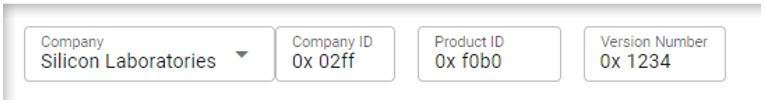
Device configuration information includes:
Company: Selected from a list of company names.
Company ID: 16-bit company identifier assigned by the Bluetooth SIG. A list of companies and their identifiers may be found on the Bluetooth SIG site.
Product ID: 16-bit vendor-assigned product identifier, vendor-specific.
Version Number: 16-bit vendor-assigned product version identifier, vendor-specific.
Elements#
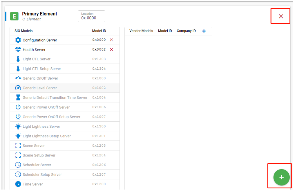
An element is an addressable entity within a node. Each node can have one or more elements, the first called the primary element and the others called secondary elements. Each element is assigned a unicast address during provisioning so that it can be used to identify which node is transmitting or receiving a message. The primary element is addressed using the first unicast address assigned to the node, and the secondary elements are addressed using the subsequent addresses. Both primary and secondary elements have a dedicated card, such as that shown in the following figure, through which they can be configured. Click the green plus symbol to add an element or select an element and click the red X symbol to remove it.
Models#
A model defines the basic functionality of a node, and a node may include multiple models. A model defines the required states, the messages that act upon those states, and any associated behaviors.
Models may be defined and adopted by the Bluetooth SIG and may also be defined by vendors. Models defined by the Bluetooth SIG are known as SIG-adopted models, and models defined by vendors are known as vendor models. SIG-adopted models are identified by a 16-bit model identifier and vendor models are identified by a 16-bit vendor identifier and a 16-bit model identifier.
Model specifications are designed to be very small and self-contained. At specification definition time, a model can require other models that must also be instantiated within the same node. This is called extending, which means a model adds functionality on top of other models.
Models that do not extend other models are referred to as root models. Model specifications are immutable. In other words, it is not possible to remove or add behavior to a model, whether the desired behavior is optional behavior or mandatory. Models are not versioned and have no feature bits. If additional behavior is required in a model, then a new extended model is defined that exposes the required behavior and can be implemented alongside the original model.
Therefore, knowledge of the models supported by an element determines the exact behavior exposed by that element.
The Bluetooth Mesh Configurator supports configuring both SIG-adopted models and vendor models through separate editors.
SIG-Adopted Model Editor#
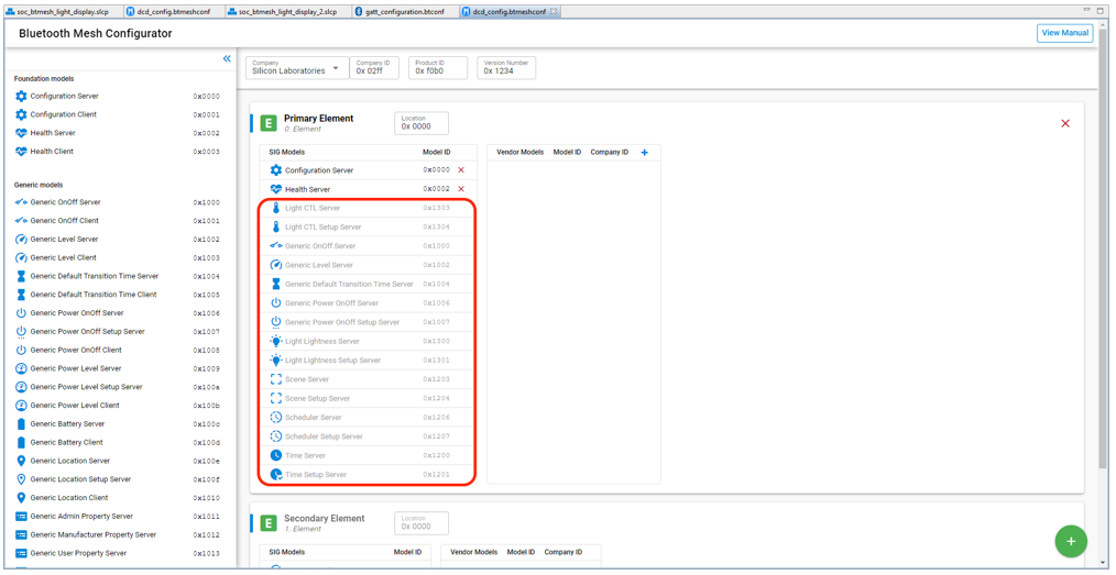
If you are using the provided model components that automatically bring in the source/header files, libraries, and configurations to the project, and also contribute the model to the DCD, you cannot edit or delete the model from the DCD manually. The model is greyed out, as shown in the following figure. In this case, all the model implementations will be generated to the project. You can modify the callbacks to adjust the application to your use case.
The drawback to using components is that you cannot edit the DCD and model information, because the models added by components are greyed out. If you want to build the DCD from scratch, for example to add a specific model to an element, uninstall all the model components. Then you can edit the DCD manually.
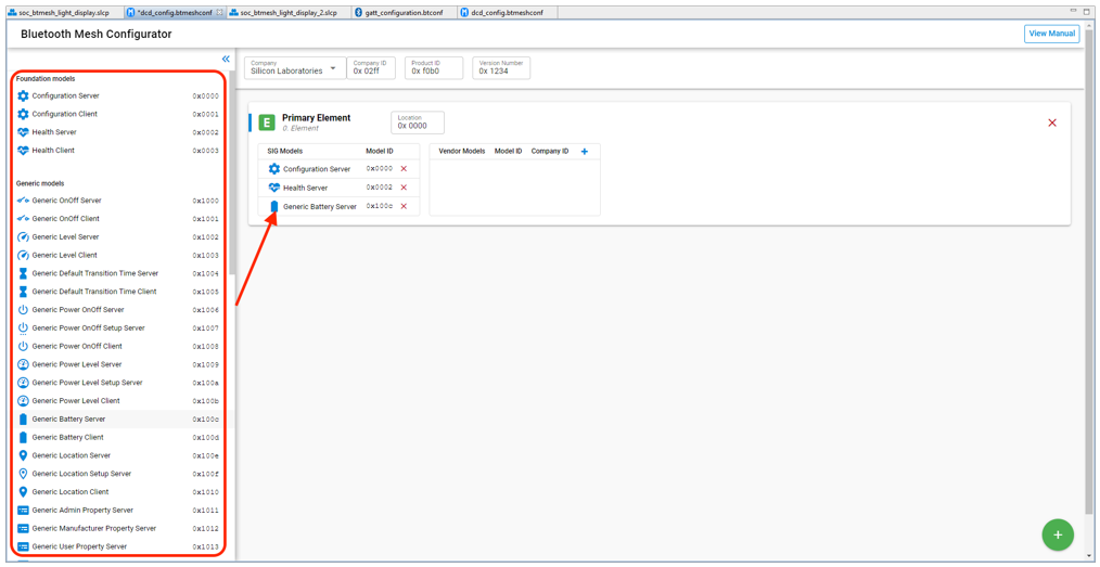
To delete a model, select it and click the red X symbol. To add a SIG-adopted model, drag the model from the left model pool to the SIG Models table in the correct element. A list of all the SIG-adopted models is displayed, and you can choose the one you want, as shown in the following figure. Note that, although all the SIG-adopted models are listed, not all of them are currently supported by the Bluetooth Mesh SDK. For the information on the supported models, see the SDK release notes.
Due to the extension mechanism of models mentioned above, attention is needed when adding models to your project. See UG472: Bluetooth® Mesh Node Configurator User's Guide for SDK v2.x for more information.
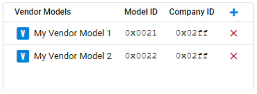
Vendor Models Editor#
Vendor models give you more flexibility when developing products not covered by the SIG-adopted models. Vendors can define their own specification in these vendor models, including states, messages, and the associated behaviors. The vendor model editor is shown in the following figure. The ID field contains the 32-bit vendor identifier and model identifier. The two least significant bytes of the ID are the vendor ID and the two most significant bytes are the model ID. In the following figure, 0x02FF is the vendor ID for Silicon Labs, and 0x0021 and 0x0022 is the model ID. Click the plus symbol to add a vendor model, or select a model and click the red X symbol to remove it.