


SEGGER SystemView#
Real-time operating system (RTOS)-based applications often require greater visibility than conventional debugging provides. Monitoring CPU load, heap usage, task scheduling, and event timing helps identify performance bottlenecks and resource constraints.
SEGGER SystemView is a real-time software analysis tool for evaluating performance and debugging embedded applications while the target is running. Most Silicon Labs development kits include an onboard J-Link debugger that provides a direct connection between SystemView and the target without requiring another debug probe.
SystemView uses the Real-Time Transfer (RTT) protocol and works with any J-Link-compatible debug probe.
Prerequisites#
Before you begin, make sure you have the following items:
Simplicity Studio 6 and the applicable Simplicity SDK
A supported Silicon Labs development kit with an onboard J-Link-compatible debugger, such as the BRD4002A/B Wireless Pro Kit Mainboard with the BRD4186C EFR32xG24 Radio Board
A FreeRTOS-based Simplicity SDK project with SystemView support
SEGGER SystemView
A USB connection between the development kit and the host computer
Basic familiarity with creating, building, flashing, and running Simplicity SDK projects
Install and License SystemView#
Through a licensing agreement with SEGGER, SystemView is available free of charge to Silicon Labs customers who develop applications for Silicon Labs wireless systems on chips (SoCs) and microcontrollers.
Download the SystemView installer from the SEGGER SystemView page.
Install and open SystemView. When the license prompt appears, select License Manager.
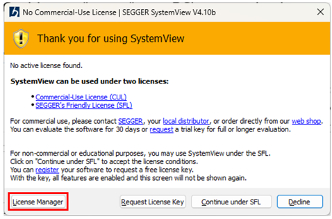
If the prompt does not appear, select Tools > License Manager in SystemView.
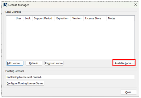
In License Manager, select Available Locks.
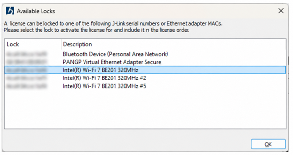
Identify the MAC address of the network adapter that you want to associate with the SystemView license, and record the address.
Note: The SystemView license is tied to the selected MAC address.
Go to the SEGGER SystemView license request page and complete the request form. In the MAC address field, enter the address that you recorded in the previous step.
After you submit the form, SEGGER sends the license key by email.
Open the email with the subject Your SystemView Activation Key for Silicon Labs Devices, and copy the complete activation key, including the
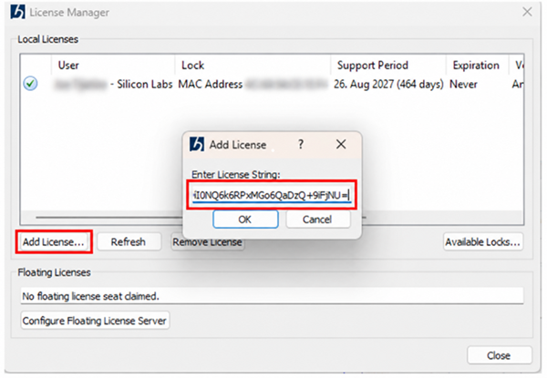
License_SVprefix.In License Manager, select Add License, paste the complete license string, and select OK. Then close License Manager.
In the license warning, select Accept.
SystemView opens and displays Licensed to {Your Name} in the window title, indicating that the license was installed successfully.
Configure the Project for SystemView#
Add the SystemView component and update the Blink project before starting SystemView.
This procedure uses the Platform - Blink Kernel FreeRTOS example project.
Complete the following configuration tasks:
Install the SystemView Component#
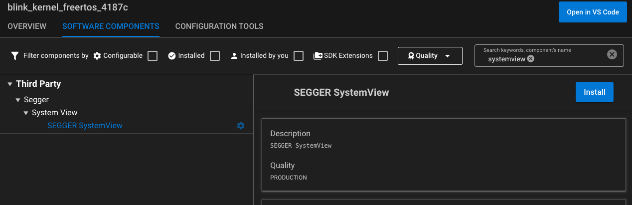
In Simplicity Studio 6, open the
.slcpfile for a FreeRTOS project, such asblink_kernel_freertos.Go to Software Components and install the SEGGER SystemView example.
Open the project in your preferred integrated development environment (IDE). In Simplicity Studio 6, select and hold the project in the Projects view, and then select Open in IDE.
Configure the RTT Buffers#
Note: Because of an issue with the SEGGER dynamic-link library (DLL), projects that use a Simplicity SDK version earlier than 2026.6.2 must change the number of RTT up and down buffers from 10 to 9.
Open
<ProjectName>/config/SEGGER_RTT_Conf.h.Set
SEGGER_RTT_MAX_NUM_DOWN_BUFFERSandSEGGER_RTT_MAX_NUM_UP_BUFFERSto9.
Configure Continuous Recording#
By default, the project uses single-shot recording, as configured in sl_main_init.c. Change the recording mode to continuous so SystemView can gather events over time.
Open
<ProjectName>/<simplicity_sdk_xxx>/platform_core/platform/service/sl_main/src/sl_main_init.c.Go to the
sl_main_init(void)function.Comment out the
SEGGER_SYSVIEW_Start();function call as shown in the following example:
void sl_main_init(void)
{
SLI_METRIC_EVENT_HANDLER_START();
#if defined(SL_CATALOG_LOG_COMPONENT_PRESENT)
sl_log_init_stage1();
SLI_METRIC_EVENT_HANDLER_SAVE("sl_log_init_stage1");
#endif
#if defined(SL_CATALOG_SYSTEMVIEW_TRACE_PRESENT) && !defined(SL_CATALOG_LOG_BACKEND_SYSTEMVIEW_PRESENT)
SEGGER_SYSVIEW_Conf();
// SEGGER_SYSVIEW_Start();
#endif
#if defined(SL_CATALOG_MEMORY_MANAGER_PRESENT) && !defined(SL_CATALOG_CPP_SUPPORT_PRESENT)
sl_memory_init();
SLI_METRIC_EVENT_HANDLER_SAVE("sl_memory_init");
#endif
...
}Increase the LED Blink Frequency#
Open
blink.cin the main project directory.Change the blink period to
50ms:#ifndef TOOGLE_DELAY_MS #define TOOGLE_DELAY_MS 50 #endifBuild the application and flash it to the development board. For more information, see the documentation under Simplicity Studio > Projects on the Silicon Labs documentation site.
After flashing the device, verify that the light-emitting diode (LED) blinks at 20 Hz.
Start a SystemView Recording#
After confirming that the device is running the application, configure SystemView for the debug adapter.
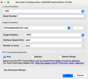
In SystemView, go to Target > Recorder Configuration.
Select J-Link.
Select the J-Link connection that you are using.
Enter the target part.
Leave the target interface set to SWD with a frequency of 4 kHz.
Leave RTT Control Block Detection set to Auto.
Select Finish.
The Recorder Configuration window contains additional parameters that you can change for your setup. If you use a USB connection and a development board, your configuration should be similar to the following example. Adjust the configuration for your hardware and debug interface.
If SystemView does not detect the RTT control block, select Address in Recorder Configuration and enter the address of the _SEGGER_RTT symbol from the project's .map file.
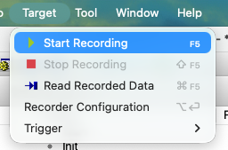
To begin recording RTOS events, go to Target > Start Recording.
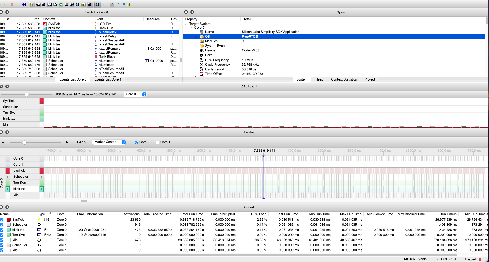
SystemView displays the recorded events in real time. The Timeline view shows when each task runs. After collecting enough events, stop the recording and analyze the results.
Explore SystemView Data#
SystemView gathers real-time events from five elements in this example: SysTick, Scheduler, Tmr Svc, Blink Task, and Idle. Tmr Svc, Blink Task, and Idle are RTOS tasks. SysTick is an interrupt, and Scheduler identifies scheduler events.
Timeline#
The Timeline view displays task and interrupt activity. If the view is not visible, go to Window > Timeline.
FreeRTOS configures SysTick with a period of approximately 1 ms by setting configTICK_RATE_HZ in FreeRTOSConfig.h:
#define configTICK_RATE_HZ ((TickType_t)1000)The timeline shows an interval of approximately 976 us between SysTick interrupts, which corresponds to the project configuration.
To go to the closest Blink Task event, select the right or left arrow next to Blink Task in the Timeline view. Zoom in to examine the sequence of events.
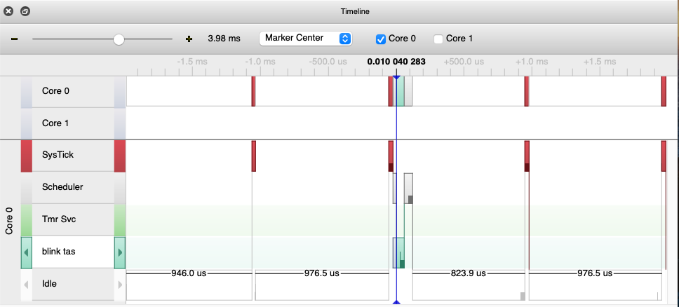
Every 50 ms, after a SysTick interrupt, the RTOS determines whether the Blink Task is ready to run based on its configured delay. After 50 ms of operating system ticks, the Blink Task resumes and toggles the general-purpose input/output (GPIO) connected to the LED.
To limit the event types shown in the timeline, clear an interrupt or task in the Context window. The window also displays timing and CPU load information.

The view also shows task types and priorities. For example, Blink Task has a priority of 1, making it the lowest-priority task after Idle. Tmr Svc has the highest priority because it is the operating system's software timer service task.
Events List#
The Events List view, typically located in the upper-left area of SystemView, shows the RTOS events that occur during operation.
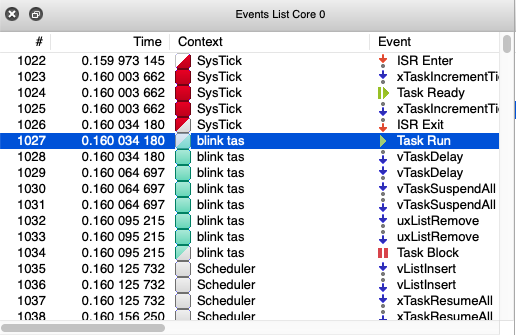
In this example, a SysTick interrupt makes Blink Task ready to run. The scheduler then starts Blink Task. After running its code, Blink Task returns to the blocked state and waits 50 ms before running again.
CPU Load#
The CPU Load view shows how tasks and events affect the CPU and can help identify optimization opportunities.

In this example, SysTick activity accounts for most of the execution time. The device remains in the Idle state for the rest of the time because the application contains only one Blink Task.