Usage Guidelines#
Configuration Parameters for Driver Package#
Download the RPI OS image from the below link : SiWx917_RCP_image_with_RPI4.img.
Download the RPI Imager tool: RPI-Imager.
Connect the empty SD card (atleast 32 GB size) to the Windows machine via the SD memory card slot/SD card reader/SD card adapter.
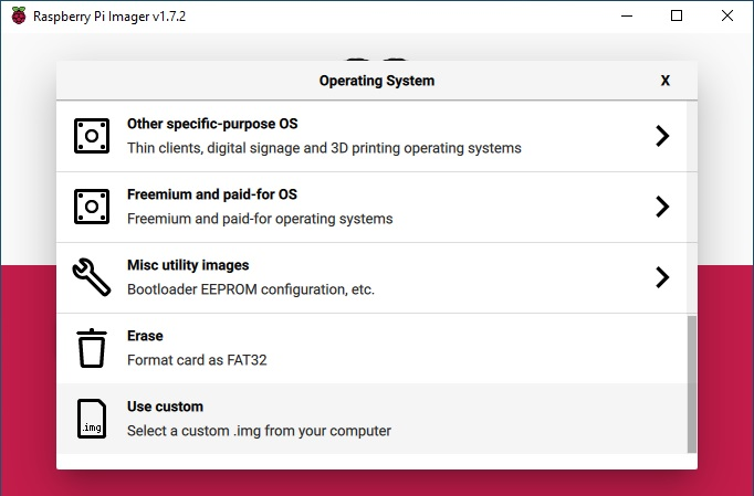
Launch the RPI imager. It will pop up the window as shown below.

Choose the OS and select Use custom icon.
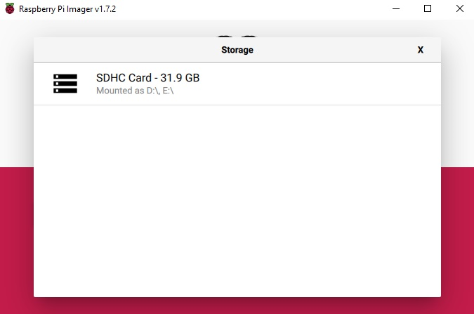
Select the RPI-4B image from the directory where the image is downloaded. Select the Choose Storage button and it will pop up the SD card partition.
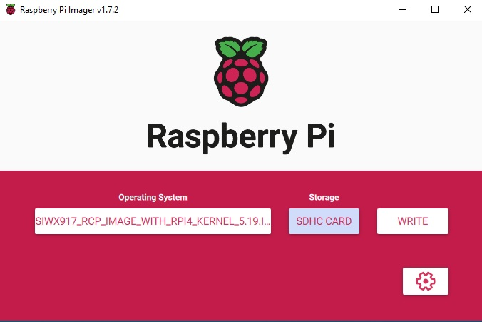
Now click on the Write button.
It will prompt for confirmation. Click, Yes.

The image will start flashing onto the selected SD card partition. Wait until the card flashing is done.

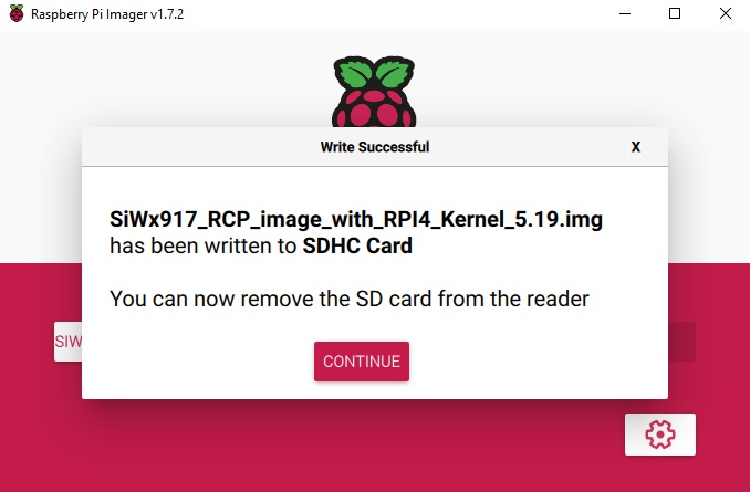
Once the flashing is complete. A window will pop up showing that the write was successful.
Remove the SD card from the SD card reader and insert it on RPI-4B Pi.
Connecting SiWT917 to Raspberry Pi 4 and Accessing Console#
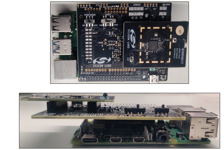
Connect the SiWT917_BRD8045B and radioboard to the 40 pin header of Raspberry Pi 4, as shown below.
Connect the 5V power adapter/power up through USB to the Type C USB port of the RPi4 board.
Connect the ethernet cable from the ethernet port on RPi to the Windows/Linux PC.
Static IP is assigned to RPI and the IP of the RPi4 is 192.168.30.10
Give the IP address for the Linux/Windows PC in the same subnet of 192.168.30.X
For example:
If Linux PC: ifconfig eth0 192.168.30.15
If Windows PC: Configure the network settings with 192.168.30.15
Check the ping to RPi4 board IP 192.168.30.10(Exp: ping 192.168.30.10).
Log in to the RPi4 Console using ssh/putty (By default, the IP address of the RPi4 is 192.168.30.10). or
User can access the RPi4 using the HDMI connector cable connected to the HDMI supported monitor.
After powering up, it will ask for username and password.
Username: pi
Password: test123
Steps to Bring up in STA Mode#
Download the si91x-rcp-driver.
Place the driver in any local path of the RPi4 home directory.
Example: <system_path> : cd /home/pi/
Note: "<system_path>" is the location where the user has downloaded/placed the SiWT917 driver in the system.
Unzip the driver using the following command.
# unzip SiWT917.x.x.x.x.zipNow user needs to enter super user mode by giving the following command and providing the correct username and password.
# sudo su
The subsection below provides the steps to configure Wi-Fi STA using startup script or manual commands. User can choose any method.
Using Startup Scripts#
User can use the script at path “<system_path>/SiWT917.x.x.x.x/release/” to run Wi-Fi concurrent mode.
Example: ./start_SiWT917.sh STA
For more details about the startup script file, refer to the Startup Script section of SiWT917 RCP Developer’s Guide.
Using Manual Steps#
Compile the driver using the following commands at path
<system_path>/SiWT917.x.x.x.x/#make clean; makeNote: For compiling from kernel source or for other embedded platforms like iMX6 platform, the user can refer to the section Compilation Steps of the SiWT917 RCP Getting Started Guide.
Before installing the driver, install the dependencies using the following commands :
# modprobe mac80211 # modprobe bluetooth # modprobe rfcommBefore installation, the user needs to stop the existing network manager and unblock WLAN from rfkill. The commands below are used to stop the network-manager on different Linux distributions.
For Ubuntu, use the following command:
# service network-manager stopFor Fedora/Raspberry Pi, use the following command:
# service NetworkManager stopTo stop rfkill blocking WLAN, use the following command:
#rfkill unblock wlan (or) # rfkill unblock all
Go to the driver package and copy all the files present in the
<system_path>/SiWT917.x.x.x.x/ Firmwarefolder to/lib/firmwareby following the commands below.# cd <system_path>/SiWT917.x.x.x.x/ # cp Firmware/* /lib/firmwareAfter compiling the driver go to the
<system_path>/ SiWT917.x.x.x.x/releasefolder and give the following commands:# insmod rsi_91x.ko dev_oper_mode = 1 rsi_zone_enabled = 0x601 # insmod sdio.ko sdio_clock = 50Check for the interface created using the command below:
# ifconfig -aFor example, if the driver is loaded successfully and wireless interface is created, then the user will see the following output:
wlan0: flags = 4098<BROADCAST,MULTICAST> mtu 1500 ether 94:b2:16:98:ac:dc txqueuelen 1000 (Ethernet) RX packets 0 bytes 0 (0.0 B) RX errors 0 dropped 0 overruns 0 frame 0 TX packets 0 bytes 0 (0.0 B) TX errors 0 dropped 0 overruns 0 carrier 0 collisions 0Note: In this test case, the wireless interface created after loading of a driver is wlan0. The interface name may vary across the systems.
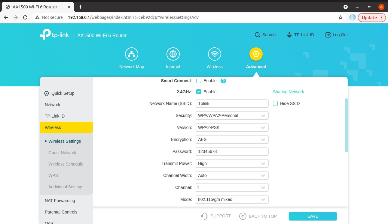
Bring up the third-party access point in the desired channel and security. For this test case setup, the TP-Link AX1500 Wi-Fi 6 Router is configured with the following credentials, as shown in the figure below.
Edit the network block present in the
<system_path>/SiWT917.x.x.x.x/release/ sta_settings.conffile which is present in the<system_path>/ SiWT917.x.x.x.x/releasefolder with the credentials of the third-party WLAN access point. For this test case, the network block is updated in the following manner:ctrl_interface=/var/run/wpa_supplicant update_config=1 #Enable this network block for CCMP/TKIP mode network={ ssid="Tplink" pairwise=CCMP TKIP group=CCMP TKIP key_mgmt=WPA-PSK psk="12345678" # bgscan="simple:15:-45:20" proto=WPA2 WPA }For more details regarding how to update the network block for other security modes in
system_path>/ SiWT917.x.x.x.x/release/sta_settings.conffile, the user needs to follow the section Configure station mode using wpa_supplicant.Run wpa_supplicant to connect SiWT917-STA to the TAP.
#wpa_supplicant -i <interface name> -D nl80211 -c <system_path>/SiWT917.x.x.x.x/release/sta_settings.conf -dddt > log & **Example : wpa_supplicant -i wlan0 -D nl80211 -c /home/ SiWT917.x.x.x.x/release/sta_settings.conf -dddt > supp.log &**To check whether the connection is successful or not use the following command:
# iwconfigIf the connection is successful, then the connected Access point SSID along with the MAC address is displayed as shown below.
wlan0 IEEE 802.11 ESSID:"Tplink" Mode:Managed Frequency:2.412 GHz Access Point: B0:A7:B9:C4:52:CA Bit Rate=39 Mb/s Tx-Power=16 dBm Retry short limit:7 RTS thr=2353 B Fragment thr=2352 B Encryption key:off Power Management:off Link Quality=80/80 Signal level=-28 dBm Rx invalid nwid:0 Rx invalid crypt:0 Rx invalid frag:0 Tx excessive retries:0 Invalid misc:18 Missed beacon:0If it is not connected to an Access point, a message "Not Associated" is displayed as shown below.
wlan0 IEEE 802.11 ESSID:off/any Mode: Managed Access Point: Not-Associated Tx-Power=0 dBm Retry short limit:7 RTS thr:off Fragment thr:off Encryption key:off Power Management:offAfter successful connection check the IP address using the below commands
# dhclient wlan0 -r # dhclient wlan0 -vTo check if the SiWT917-STA has been assigned with an IP address from the third-party WLAN access point , the user can give the following command:
#ping <IP_adrress of TAP> Example: ping 192.168.0.1For example, if SiWT917-STA has successfully got IP, we will see the following output.
PING 192.168.0.1 (192.168.0.1) from 192.168.0.228 wlan0: 56(84) bytes of data. 64 bytes from 192.168.0.1: icmp_seq=1 ttl=64 time=26.8 ms 64 bytes from 192.168.0.1: icmp_seq=2 ttl=64 time=10.8 ms 64 bytes from 192.168.0.1: icmp_seq=3 ttl=64 time=4.00 ms 64 bytes from 192.168.0.1: icmp_seq=4 ttl=64 time=6.25 ms 64 bytes from 192.168.0.1: icmp_seq=5 ttl=64 time=1.77 ms 64 bytes from 192.168.0.1: icmp_seq=6 ttl=64 time=5.05 ms 64 bytes from 192.168.0.1: icmp_seq=7 ttl=64 time=2.18 ms 64 bytes from 192.168.0.1: icmp_seq=8 ttl=64 time=5.63 ms 64 bytes from 192.168.0.1: icmp_seq=9 ttl=64 time=2.72 ms 64 bytes from 192.168.0.1: icmp_seq=10 ttl=64 time=3.01 ms 64 bytes from 192.168.0.1: icmp_seq=11 ttl=64 time=2.32 ms 64 bytes from 192.168.0.1: icmp_seq=12 ttl=64 time=3.14 ms --- 192.168.0.1 ping statistics --- 12 packets transmitted, 12 received, 0 % packet loss, time 11019 ms rtt min/avg/max/mdev = 1.766/6.133/26.773/6.665 msFor example, if SiWT917-STA has not assigned with an IP address, we will see below output for the ping command.
# ping: connect: Network is unreachable