Example Use Cases#
M4 Sensing over a ULP Peripheral with Intermittent Wi-Fi Communication#
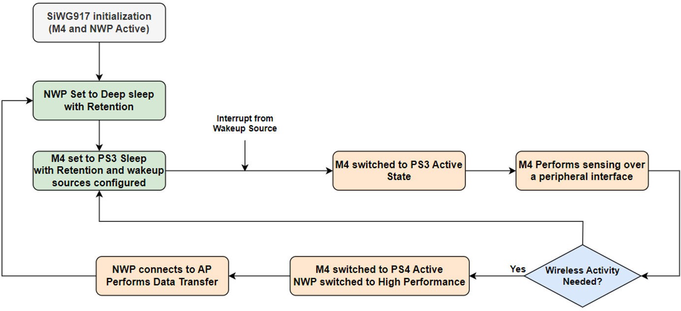
The reference application flow can be illustrated as follows:
SiWG917 comes out of RESET, NWP, and M4 initialization.
NWP set to unconnected sleep (Standby Power Save/without Retention).
M4 set to PS2 Sleep with retention for 200 milliseconds.
M4 gets back to PS2 Active upon RTC timer expiry; M4 receives data from ULP peripheral/sensor.
M4 processes the data received, based on data, and a decision is taken to execute either step-6 or step-8.
If wireless activity is needed, M4 switches back to PS4, and NWP is switched back to High Performance Mode.
NWP is configured as WLAN station, connects to a AP, performs data transfer over WLAN, disconnects from WLAN, and execution continues from step-2.
If wireless activity is not needed, execution continues from step-3.
NWP in Connected Power Save, M4 Performing Activties Based on the Wireless Message Received (Smart Lock)#
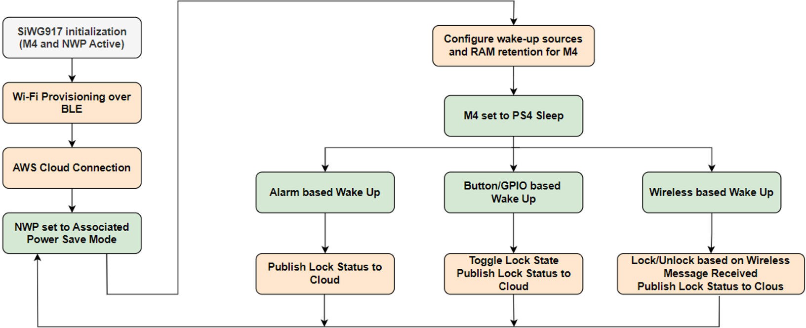
The application flow can be understood as the following:
SiWG917 comes out of RESET, NWP, and M4 initialization.
NWP configured as WLAN station, connects to AP, connects to AWS Cloud over MQTT.
NWP set to Connected Power Save (Associated Power Save).
M4 set to PS4 sleep with retention having RTC timer, UULP GPIO, and Wireless message as wakeup sources.
Upon Wireless based wakeup, based on the wireless message received, the smart lock is either locked, unlocked, or simply the current state of lock is published to AWS Cloud.
Upon GPIO based wakeup, the smart lock status is toggled (if the device is in Locked state, the state is switched to Unlocked), and updated lock state is published to AWS Cloud.
Upon every RTC timer expiry, the device wakes up and publishes the current state of lock to AWS Cloud.
Once the desired functionality is complete, the M4 permits NWP to sleep and execution continues from step-4.
Neutral Less Switch#
Neutral-less switch allows for smart switch installation without the need for a neutral wire, making it ideal for retrofitting existing homes. This design ensure seamless integration with smart lighting systems, enhancing convenience and energy efficiency. This application is designed to minimize current consumption by optimizing the NWP wireless scan and connection phases.
The application has the below functionality:
M4 and NWP are initialized.
NWP configured as WLAN station connects to the Access Point, and gets the IP address via DHCP.
The scan process is as follows:
Each channel is scanned for 30 milliseconds.
NWP is set to
STANDBY_POWERSAVE_WITH_RETENTIONfor 100 milliseconds.The above sequence is repeated for each channel.
There is an intermediate phase between WLAN scan and join, during which passphrase is translated to PSK, which lasts about 1 second. NWP is set to
STANDBY_POWERSAVE_WITH_RETENTIONduring this phase, to reduce current consump-tion to 19 mA from 50 mA.After establishing the WLAN connectivity, NWP is set to
ASSOCITED_POWERSAVEand IP configuration via DHCP is per-formed.
By default, the WLAN disconnection scenario is handled at firmware level wherein the WLAN reconnection attempts are made with NWP being in the Active state. In this application, configuration is such that the rejoin algorithm at firmware level is bypassed and it is instead handled at the application level.
NWP is set to STANDBY_POWERSAVE_WITH_RETENTION and rejoin process is performed with the optimizations in place.
The following table shows optimized SiWG917 current consumption.
State | Average Current Consumption | Time Taken |
|---|---|---|
WLAN scan | 25.4 mA | 1.31 s |
WLAN scan to connection | 18.5 mA | 1.46 s |
WLAN IP configuration (Using DHCP) | 10 mA | 1.04 s |