Getting Started with WiSeConnect™ SDK v3.x and STM32™ Host in NCP Mode#
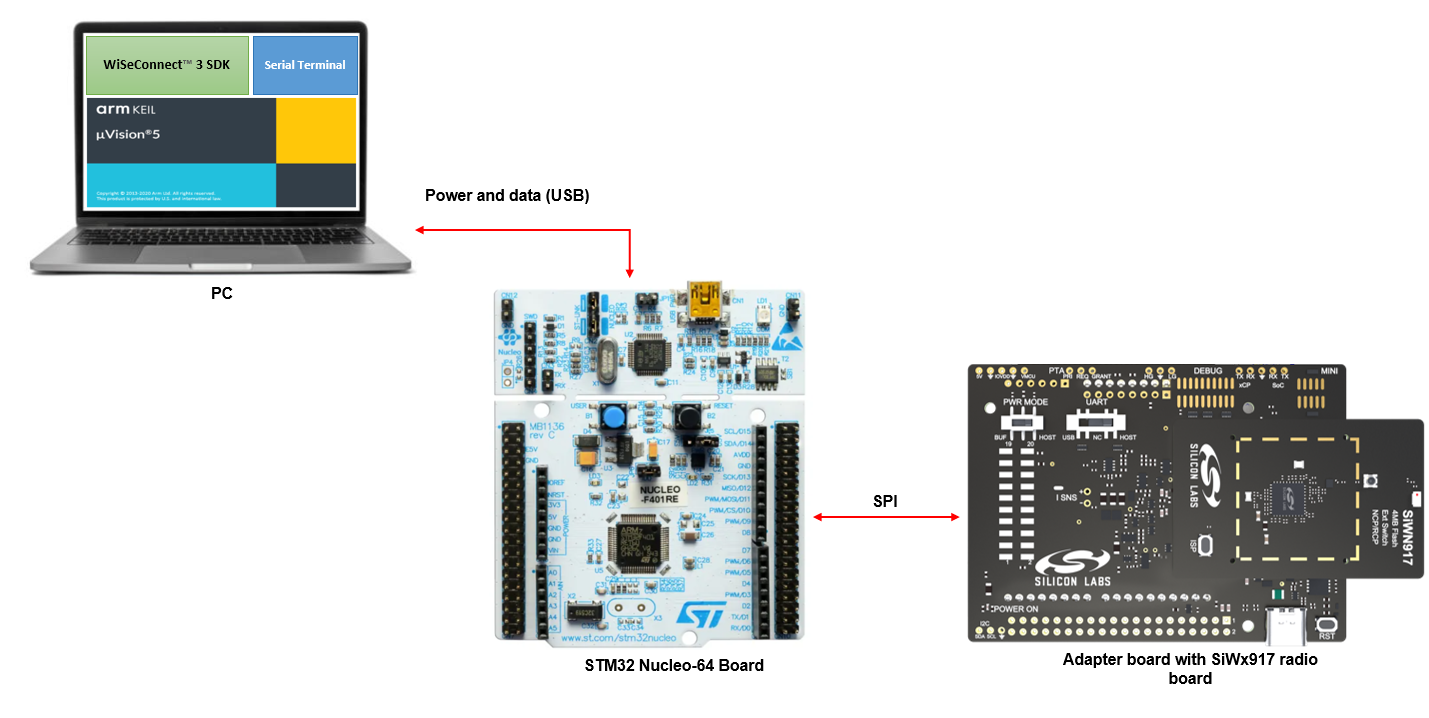
This guide describes how to get started with developing an application for the SiWx91x™ chipset family using the WiSeConnect™ SDK v3.x with an STMicroelectronics STM32F411RE™ microcontroller unit (MCU) host in Network Co-Processor (NCP) mode, where the application runs on the STM32™ host and the connectivity stack runs on the SiWx91x chipset.
Note: The output images in this guide are for illustration purposes only. Details such as board names and version numbers may not exactly match the product.
Prerequisites#
Note: The hardware and software requirements in this section are specific to the example recommended with this guide in the Open an Example Project section. If you are working with a different example, refer to its README page for the hardware and software requirements. To see the README page of a specific example, click on the Go to README link next to it in the Examples page.
Software#
Note: We recommend using the latest WiSeConnect SDK version.
Hardware#
Wi-Fi Access Point (802.11 ax/b/g/n)
Silicon Labs BRD4346A - SiWx917 Wi-Fi 6 and Bluetooth LE 4MB Flash Co-Processor Radio Board (hereafter referred to as SiWx917 radio board).
Silicon Labs BRD4357A - SiWx917 Wi-Fi 6 and Bluetooth LE 4MB Flash Co-Processor Radio Board (hereafter referred to as SiWx917 radio board).
Silicon Labs BRD8045C - Shield Adapter Board for SiWx917 Co-Processors (hereafter referred to as adapter board).
STMicroelectronics NUCLEO-F411RE - STM32F411RE Nucleo-64 Development Board (hereafter referred to as STM32 development board).
Windows PC with a USB port
Mini B and type C USB cables compatible with the computer's USB port (for e.g., type C to type A if the computer has a type A USB port).
Install Keil MDK#
You may setup Keil MDK in this section while waiting to receive the hardware.
Download MDK-arm, install it, and set up the development environment by referring to the instructions on the Keil website.
Update SiWx91x Connectivity Firmware#
Note: The SiWx917 connectivity firmware version is tightly coupled with the WiSeConnect 3 extension version. You must update the SiWx917 connectivity firmware when:
you first receive an SiWx917 shield expansion kit
you first receive an SiWx917 co-processor radio board, or
you upgrade or downgrade your github release of the WiSeConnect SDK v3.x.
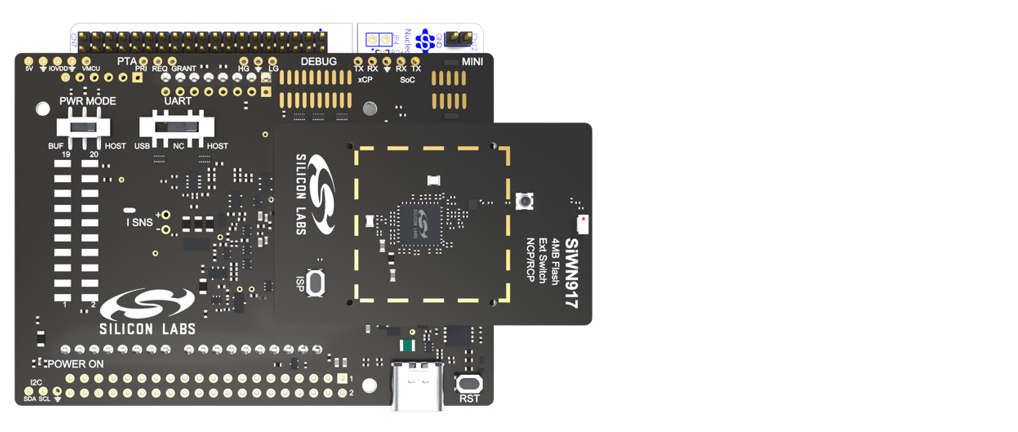
Plug the SiWx917 radio board into the radio board connectors of the adapter board as shown below.
Make sure the UART switch on the adapter board is in the USB position.
The PWR MODE switch on the adapter board is in either the BUF or HOST position.
Connect the adapter board to the CN6, CN5, and CN9 headers of the STM32 development board.
Connect the STM32 development board to your computer using a mini B USB cable.
Note: Ensure to erase the STM32's flash while doing SiWx917 NCP's firmware update.
Connect the USB port of the adapter board to your computer's USB port using a type C USB cable.
Download Simplicity Commander and extract the downloaded archive. For example, the downloaded archive will be named SimplicityCommander-Windows.zip on Windows.
Extract the commander_xxx archive present in the root folder of the Simplicity Commander archive extracted in the previous step (for example, Commander_win32_x64_1v16p10b1648 on Windows). In this example, 16 is the minor version, 10 is the patch version, and 1648 is the build number of the Simplicity Commander version downloaded.
Navigate to the Simplicity Commander sub-folder under the commander_xxx archive extracted in the previous step.
Double-click
commander.exeto open Simplicity Commander.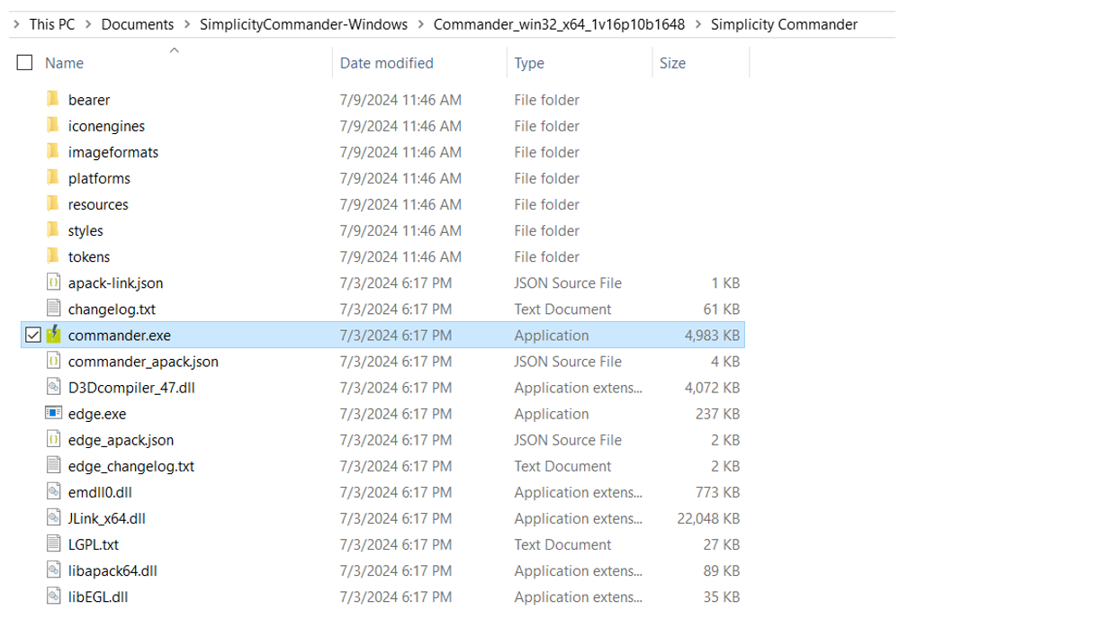
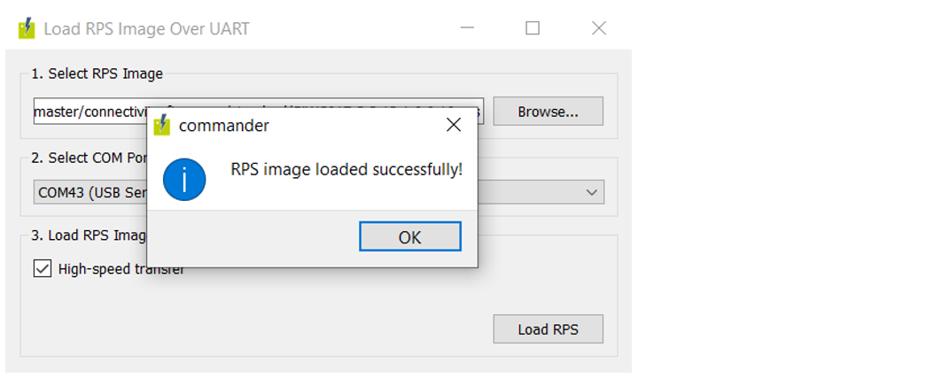
In the Simplicity Commander window, select Utilities > Load RPS Image Over UART...
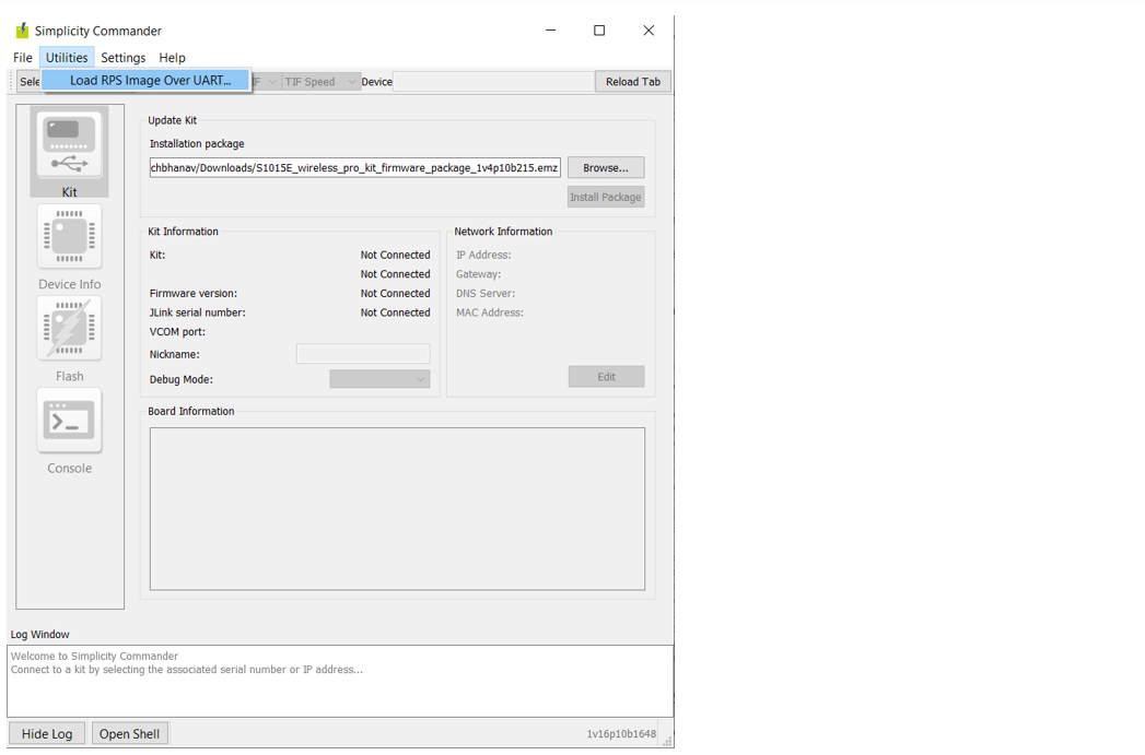
The Load RPS Image Over UART window is displayed.
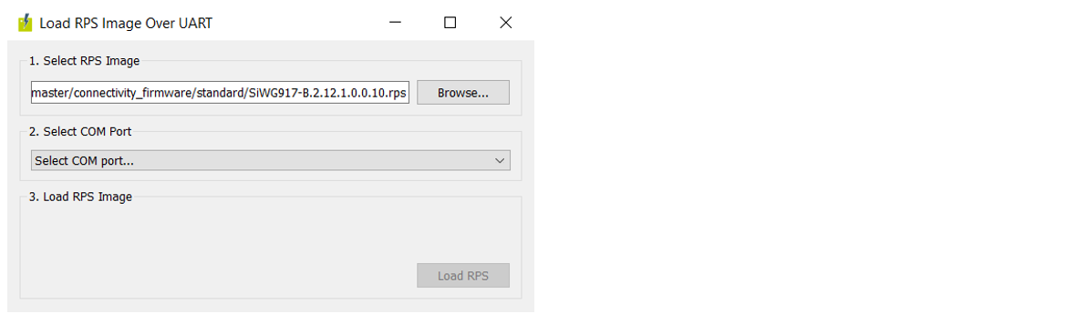
Click Browse next to the Select RPS Image field.
Locate and select the firmware file to flash from within the
connectivity_firmware/standardsub-folder of the WiSeConnect 3 extension path.Note: The
connectivity_firmware/litesub-folder can be ignored since the Lite OPN is not supported in NCP mode.Under Select COM Port, select the COM port for the connected adapter board.
Under Load RPS Image, make sure High-speed transfer is selected.
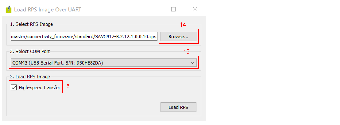
Note: When High-speed transfer is selected, Simplicity Commander sets the baud rate to 921600 before performing the firmware update.
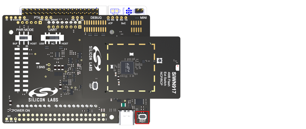
Press the RST button on the adapter board.
Click Load RPS to update firmware.
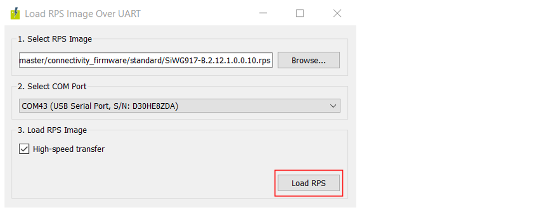
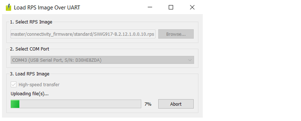
Note: It takes around 2 minutes to perform a firmware update.
On successful firmware update, the following message is displayed: "RPS image loaded successfully!".
Connect the Boards to a Computer#
Plug the SiWx917 radio board into the radio board connectors of the adapter board as shown below.
Connect the adapter board to the CN6, CN5, and CN9 headers of the STM32 development board.
Connect the STM32 development board to your computer using a mini B USB cable.
Note: The following table describes the connections between the adapter board (BRD8045C) and STM32 development board:
Signal Name
STM32 Pin Number
BRD8045C Pin Number
Description
5V Power Supply
CN6.5
P102.5
Power supply from STM32 to BRD8045C
3V3 Power Supply
CN6.4
P102.4
Power supply from STM32 to BRD8045C
GND
CN6.6
P102.6
Ground connection
SPI Clock
CN5.6 / PA5
P101.6
SPI connection - clock synchronization
SPI MISO
CN5.5 / PA6
P101.5
SPI connection - data transfer from SiWx917 to STM32
SPI MOSI
CN5.4 / PA7
P101.4
SPI connection - data transfer from STM32 to SiWx917
SPI CS
CN5.3 / PB6
P101.3
SPI connection - client selection
Reset
CN5.2 / PC7
P101.2
STM32 uses this to reset the SiWx917
GPIO Interrupt
CN5.1 / PA9
P101.1
SiWx917 uses this to initiate data transfer to STM32
Sleep / Wake Indication
CN9.5 / PB5
P103.5
SiWx917 uses this to indicate sleep / wake state to STM32
Sleep / Wake Request
CN9.3 / PA10
P103.3
STM32 uses this to send sleep / wake requests to SiWx917
Note: The PWR MODE switch on the adapter board supports the following modes of powering up the SiWx917 chipset:
HOST position: When the switch is in this position, the SiWx917 chip draws current from the 3.3 V source of the STM32 development board without the intervention of the adapter board's voltage buffer.
BUF position (default): When the switch is in this position, the voltage buffer of the adapter board draws current from the 5 V source of the STM32 development board, converts it to 3.3 V, and supplies it to the SiWx917 chip.
Open an Example Project#
Note: Before opening an example project, clone the WiSeConnect SDK v3.x github repo if not already done.
Open the Keil µVision integrated development environment (IDE) tool.
Select Project > Open Project... from the menu.

Navigate to the path where you cloned the WiSeConnect SDK v3.x github repo.
Navigate to the
keil_projectsub-folder of an STM32 example available with the WiSeConnect SDK v3.x.Note: See the STM32 Host column in the Examples page to find an STM32 example, then click on the GO to README link next to it. The
keil_projectfolder will be in the same location as the README page.Note: We recommend using the Wi-Fi - Throughput example with this guide.
Select the
.uvprojxfile in the folder and click Open.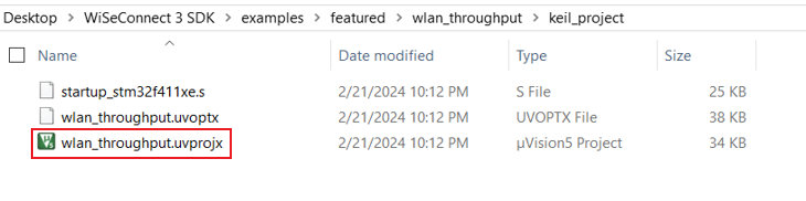
Configure an Application#
Configure the settings for your example. For Wi-Fi - Throughput (the recommended example for this guide), see the Application Build Environment section in the README page for configuration instructions.
Build an Application#
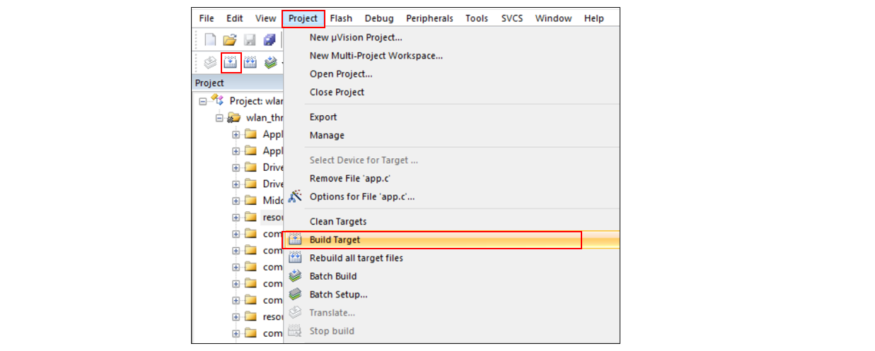
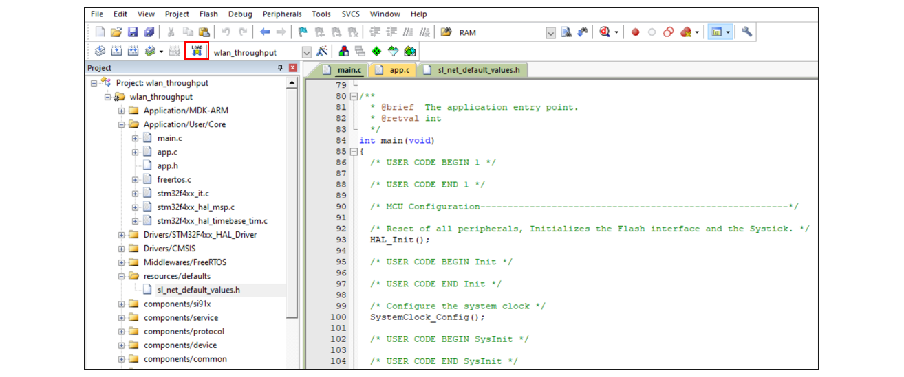
To build an application, select Project > Build Target from the menu or alternatively, click the Build button in the toolbar.
Flash an Application#
Open Tera Term on your computer and connect the serial COM port of the STM32 development board to your computer's USB port.
Click the Download code to flash memory button on the toolbar.
The application output will be displayed in the Tera Term window.
For Wi-Fi - Throughput (the recommended example for this guide), refer to the Test the Application section of the README page to explore its output. The other sections of the README like the Purpose/Scope section and Overview section (not present in some README's) provide more information about the example.
Note: See the Examples page to explore all available examples and view their README pages.
Debug an Application#
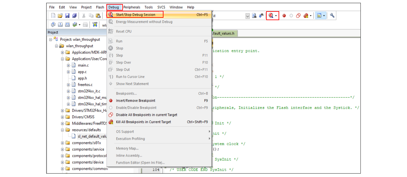
Select Debug > Start/Stop Debug Session from the menu.
You may also click the Start/Stop Debug Session button in the toolbar.
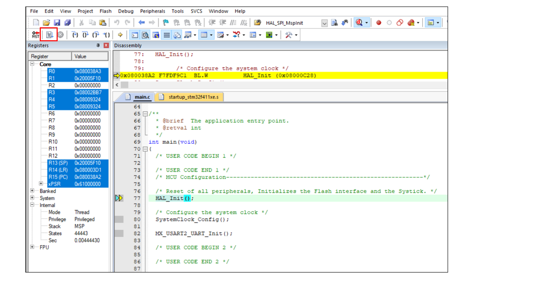
The Keil µVision IDE switches to the Debug perspective and the execution halts at the
main()function in the application.Click the Run button in the toolbar.
You may halt the execution at desired lines of code in the application by setting a breakpoint. See the Keil µVision User Guide.