Flash Loader – Example#
This section shows the steps on how to use the SEGGER template files to program the SiWx917 using the SEGGER JFlash.
Note: The SiWx917 SoC is not SEGGER Licensed, we included the Device name locally in JLinkDevices.xml file to shows this example.
Prerequisites#
The following hardware and software are required for programming the device.
Hardware#
SiWG917 SoC Kit (BRD4338A radio board + 4002A base board)
USB to Type C cable for powering the kit and flashing the application
A PC with USB ports
SEGGER J-Trace Pro with power cable
J-Link Adapter CortexM (You would get this with the J-Trace Pro when purchased)
20-position socket to socket connector cable
Software#
J-Link software (This example is verified with the version V7.96f.)
Blinky example binary file can be downloaded here
Source Code for Flash Loader – Download here
Keil IDE (This example is verified with MDK version 5.29.0.0)
Simplicity Commander: Download here
Setup#
The image below illustrates the setup.
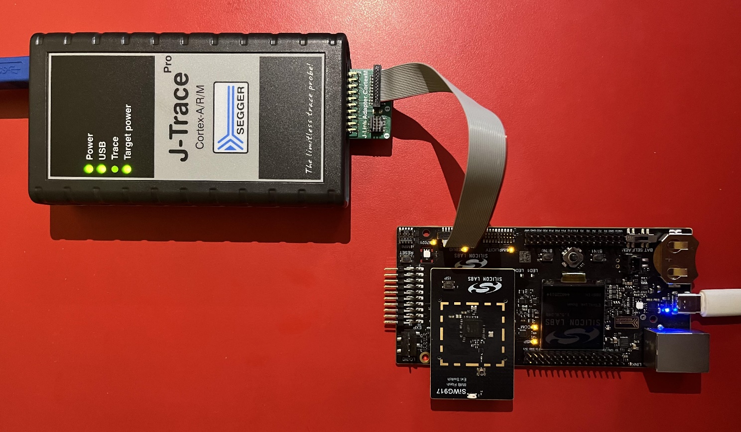
The SiWx917 and the J-Trace are connected to a PC.
The SiWx917 debug pins (on the 4002A board) and J-Trace J-Link Adapter CortexM – Target pins are connected using a socket-to-socket connector.
Make sure the J-Trace Target power light is ON after connecting the socket-to-socket connector.
Programming the SiWx917 SoC with JFlash#
To program the SiWx917 SoC using the JFlash, you need a .elf file which is generated in the Keil IDE by compiling the Si917_Flashloader project.
The flash programming involves the following steps, which are explained in detail in the sub-sections.
Generate the .ELF file in Keil IDE.
Add the SiWx917 device to SEGGER devices (locally).
Copy the .ELF file to the J-Link folder.
Erase the SiWx917 chip.
Program the SiWx917 using the JFlash.
Generate .ELF File in Keil IDE#
The following steps explain how to generate the Si917_Common_Flash.elf file.
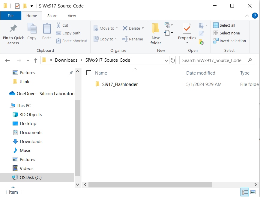
Download the SiWx917_Source_Code mentioned in the Software section.
Unzip the SiWx917_Source_Code. It should be as below.
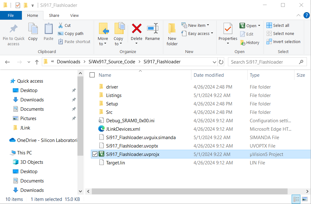
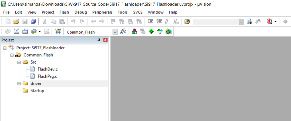
Got the Keil project path: [Downloaded_Path]\SiWx917_Source_Code\Si917_Flashloader. Open the Si917_Flashloader.uvprojx Keil project file which will open the Keil IDE with this project file.
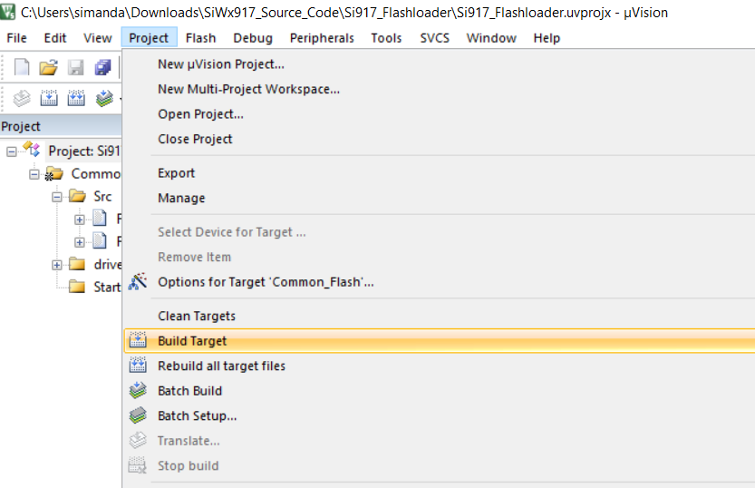
Build the Project. This is generating the Si917_Common_Flash.elf file.
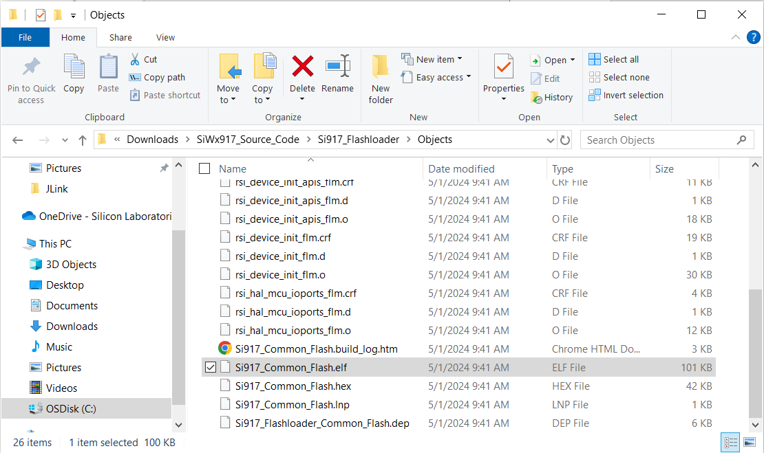
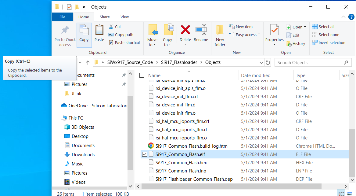
Go to the path: [Downloaded_Path]\SiWx917_Source_Code\Si917_Flashloader\Objects. You should see the Si917_Common_Flash.elf file.
Add SiWx917 Device to SEGGER Devices (Locally)#
The following steps explain how to add the SiWx917 device to the SEGGER device locally.
Download and Install the SEGGER J-Link software mentioned in the Software section.
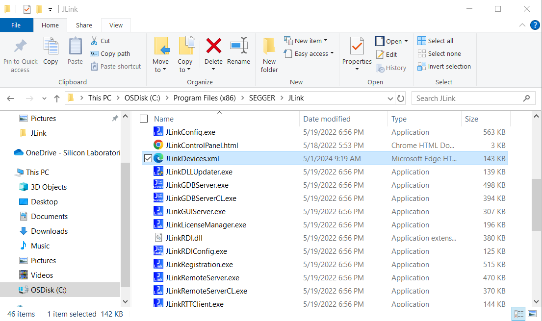
Once installed, go to the path: [Installed_Path]\ SEGGER\Jlink. Example: Here it is installed in the path: (C:\Program Files (x86)\SEGGER\Jlink). Open the JLinkDevices.xml file with an editor of your choice.
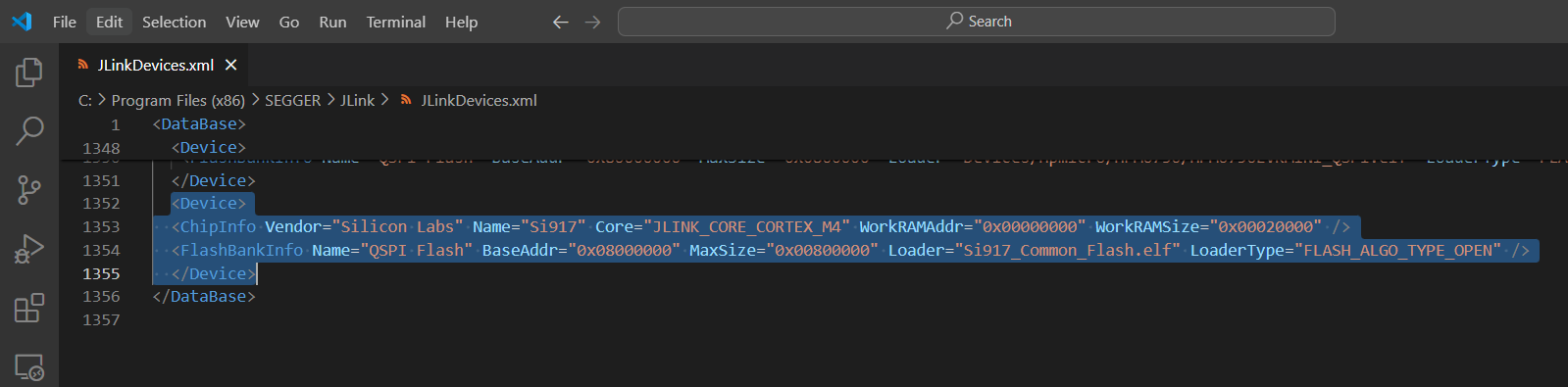
In the JLinkDevices.xml file, go to the end of the file and add the following text and then save the file as shown below.
<Device> <ChipInfo Vendor="Silicon Labs" Name="Si917" Core="JLINK_CORE_CORTEX_M4" WorkRAMAddr="0x00000000" WorkRAMSize="0x00020000" /> <FlashBankInfo Name="QSPI Flash" BaseAddr="0x08000000" MaxSize="0x00800000" Loader="Si917_Common_Flash.elf" LoaderType="FLASH_ALGO_TYPE_OPEN" /> </Device>
Copy the .ELF file to the J-Link Folder#
Copy the Si917_Common_Flash.elf file generated in Step 5 in Section Generate .ELF File in Keil IDE as shown below.
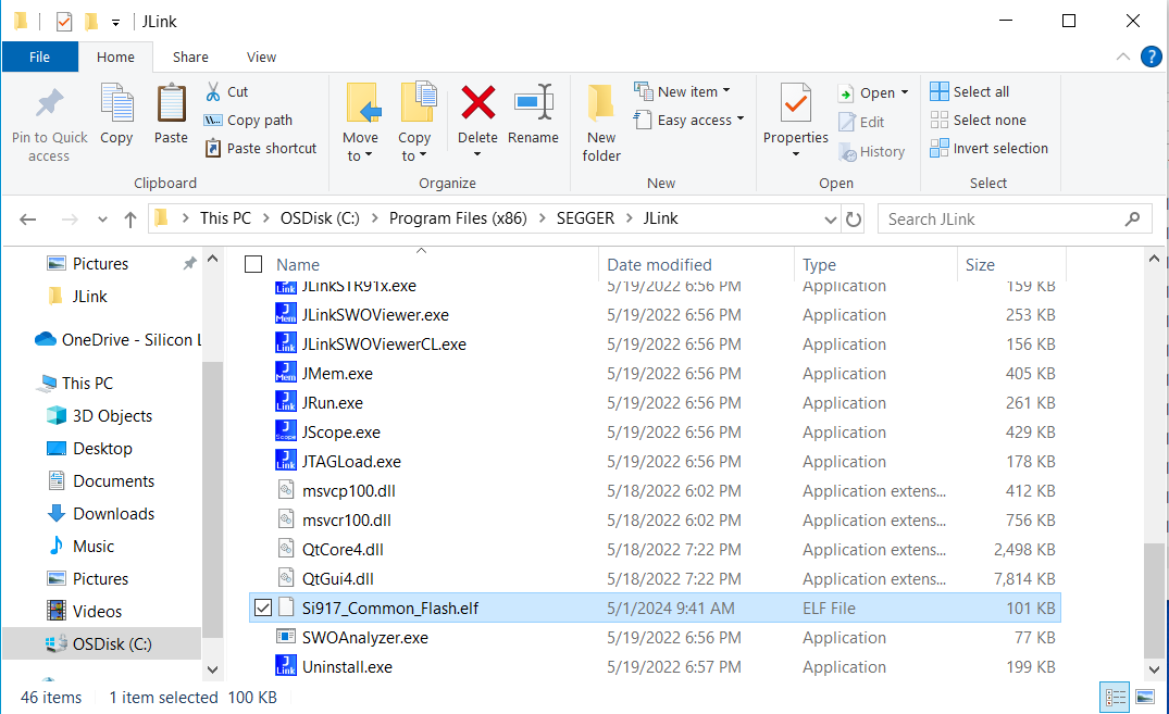
Paste the copied Si917_Common_Flash.elf file in the path: [Installed_Path]/SEGGER/Jlink as shown below.
Erase Chip - SiWx917#
To confirm an example is loaded through the flash loader, first, erase the SiWx917 chip and keep it in IN mode using the Simplicity Commander by following the steps below.
Download and Install Simplicity Commander mentioned in the Software section.
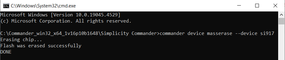
Go to the path: [Installed_Path]\Simplicity Commander. Open Terminal and give the command: commander device masserase --device si917
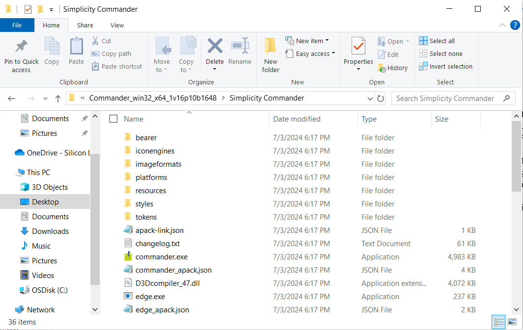
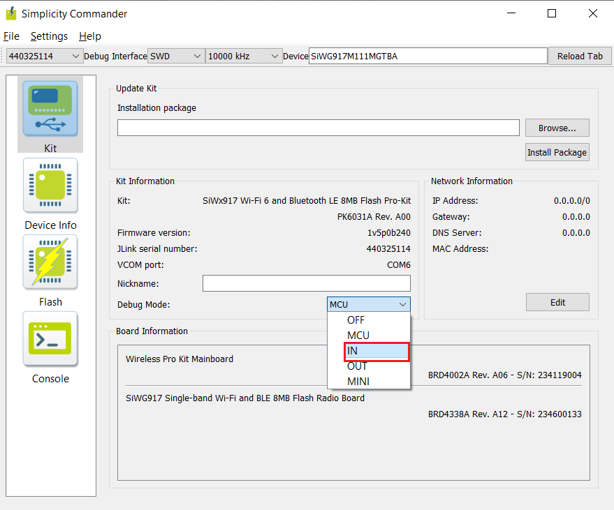
Go to the path: [Installed_Path]\Simplicity Commander. Double click the commander.exe.
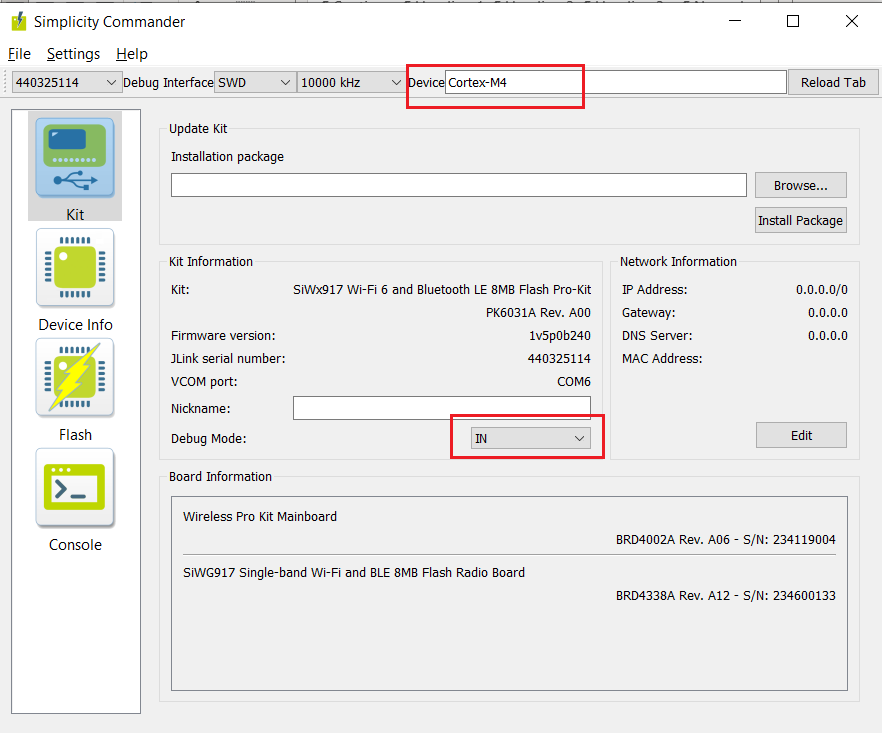
Click on Kit, change the Debug Mode from MCU to IN.
Upon changing the Debug Mode, the Device will be shown as Cortex M4.
Program Using the JFlash#
This section provides the steps to program the SiWx917 SoC using the JFlash.
Go to the Path: [Installed_Path]\SEGGER\Jlink. You will find JFlash.exe in it.
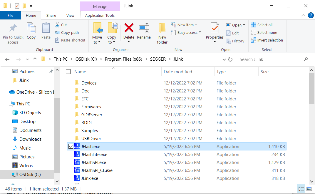
Double click on JFlash.exe. This will open the SEGGER JFlash.
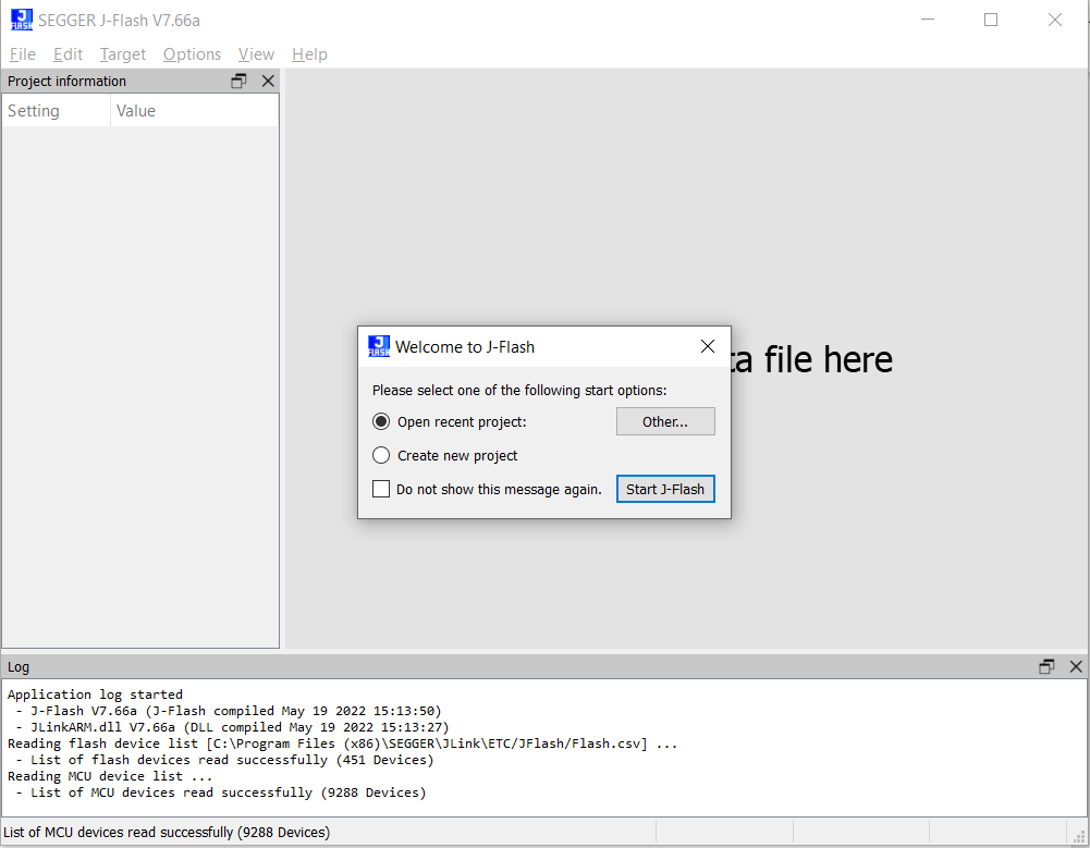
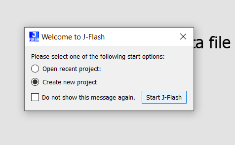
Select “Create new project” and click on Start J-Flash.
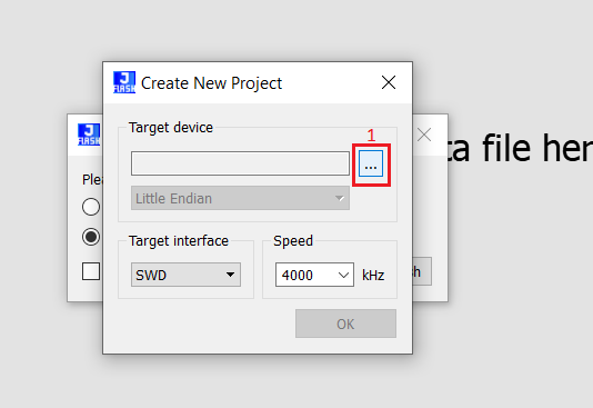
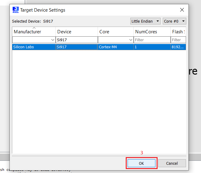
Click on the “…” under the Target device. You will be re-directed to Target Device Settings. Search for Si917 under Device column and select it. Next, click on OK.
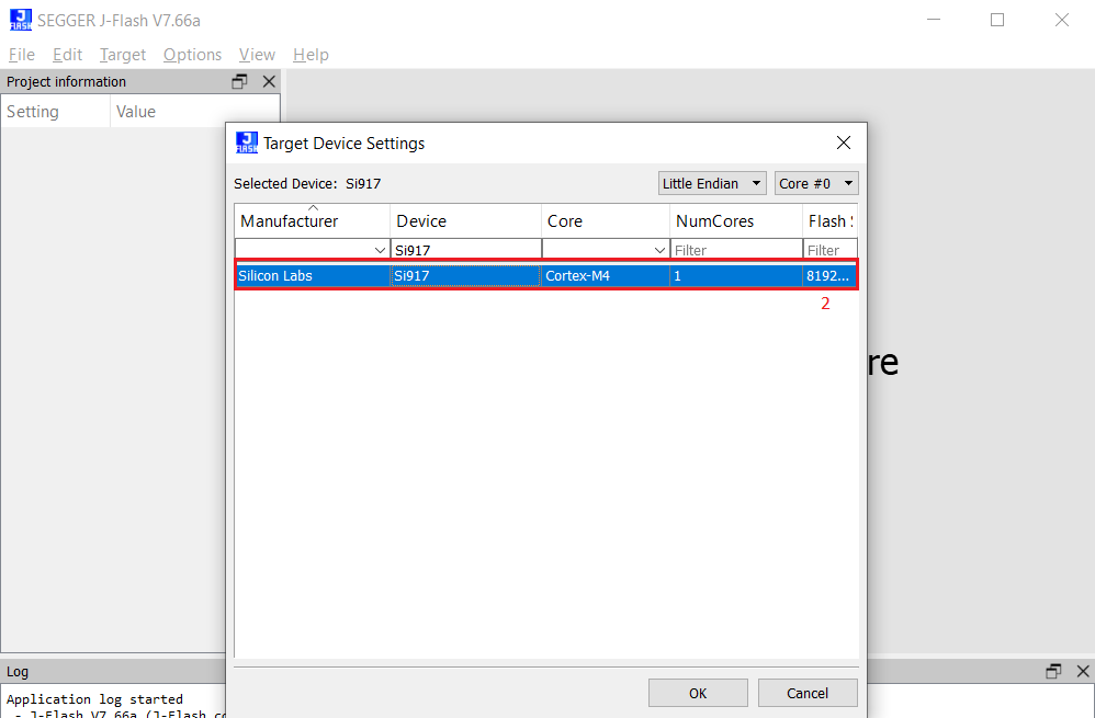
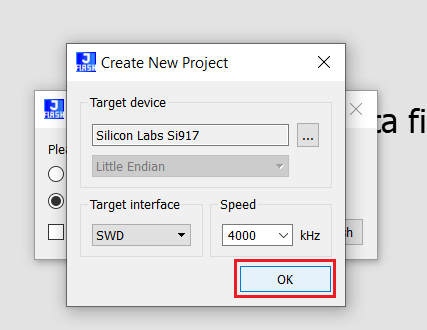
In the Create New Project Window, click on OK.
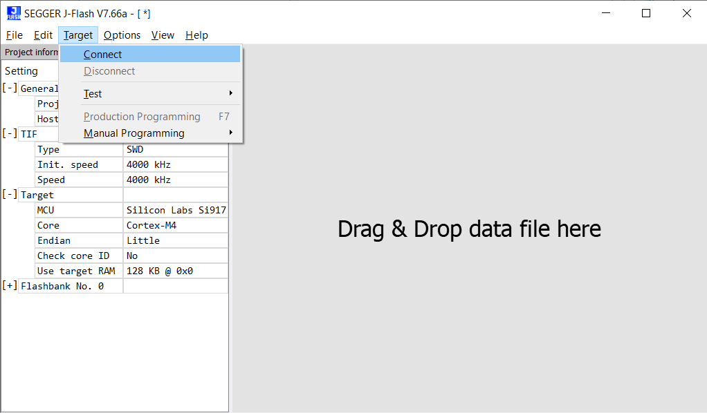
Next, click on Target → Connect.
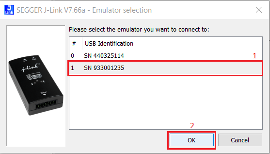
In the Emulator selection pop-up window, select the J-Trace S/N. You can see the S/N on the backside of the J-Trace. Select the correct SN in the Emulator selection window. (Example: In the image below, the J-Trace S/N is 933001235, so SN 933001235 is selected). Next, click on OK.
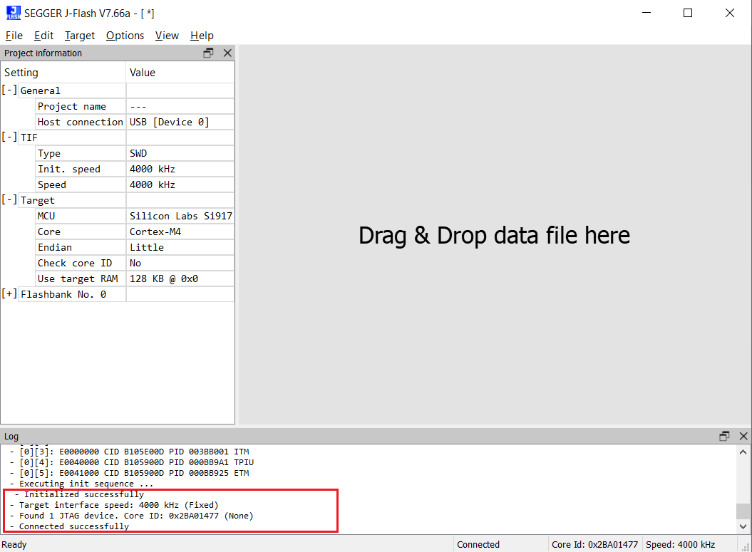
Upon successful connection, you will see “Connected successfully” in the log window as shown below.
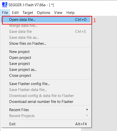
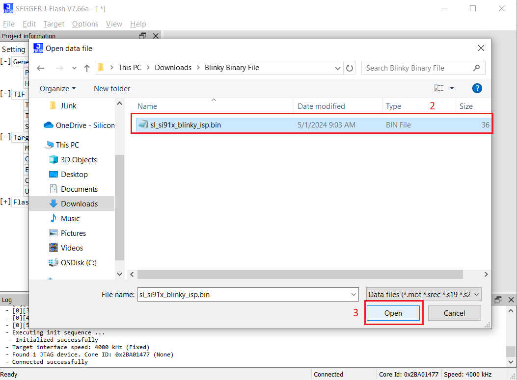
Click on File → Open data file…, and then go to the path where you downloaded the Blinky Binary file mentioned in the Software section. Next, select the sl_si91x_blinky_isp.bin file and click on Open.
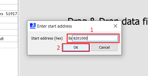
Next, in the Enter start address pop-up window, give the Start address as 0x8201000 (This is the M4 MBR Start address). Then, click on OK.
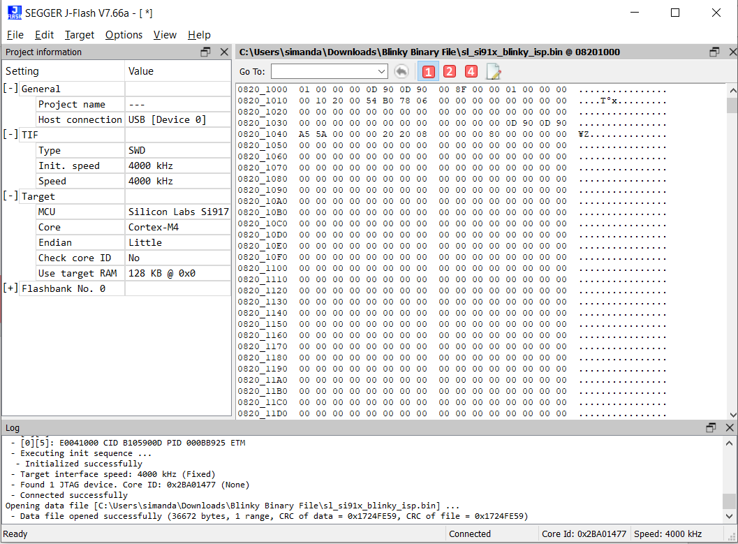
Upon successful opening of the binary file, the JFlash screen will be shown as below.
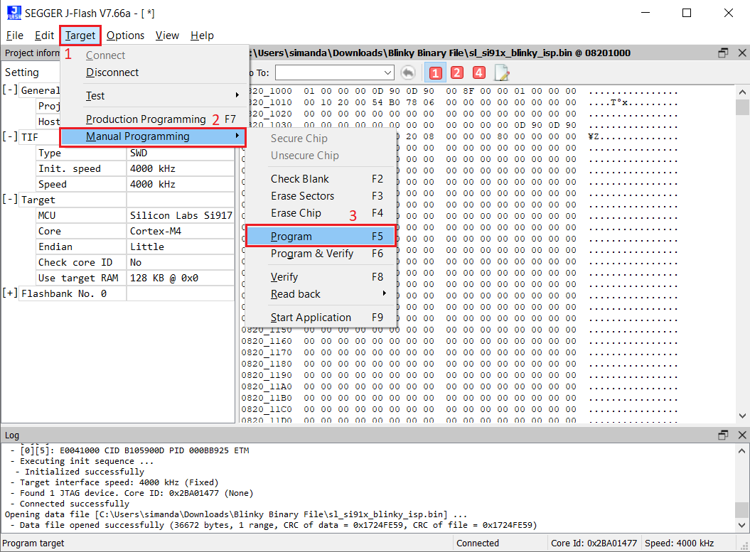
To flash the blinky application onto the SiWx917 device, click on Target → Manual Programming → Program.
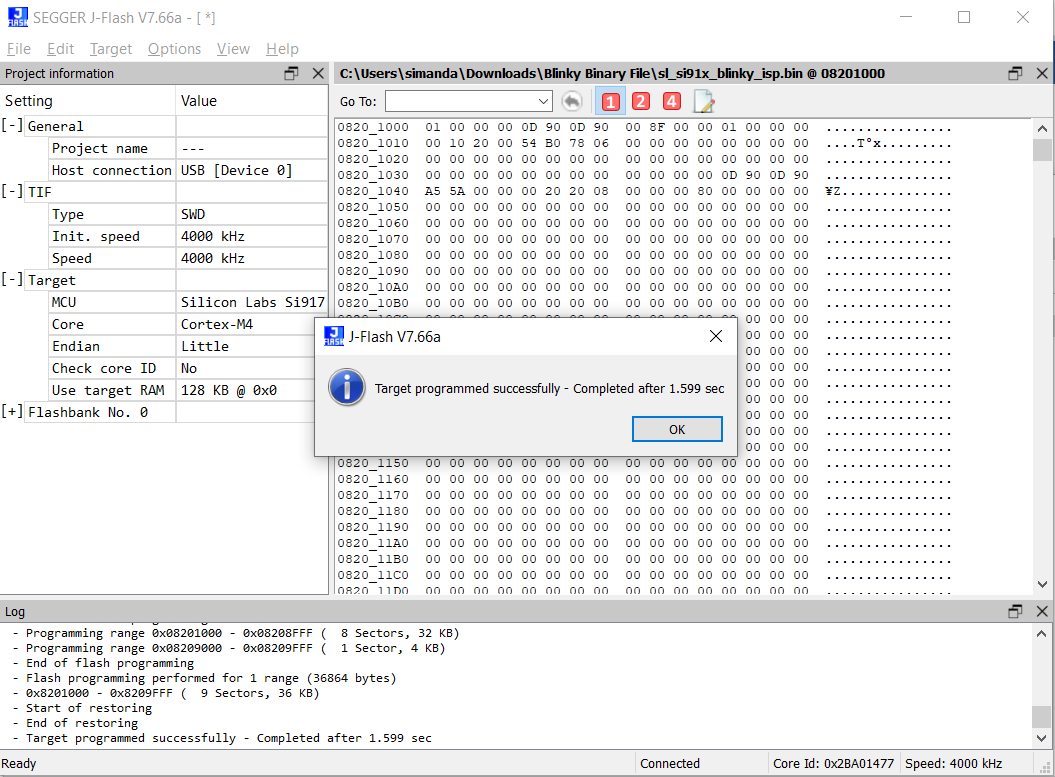
Upon successful programming, you will see “Target programmed successfully”.
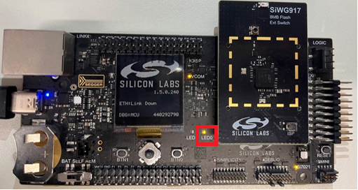
After programming successfully, you will see the LED0 on the board blinking continuously. This proves that the application is flashed through the JFlash and is running as expected.