Developing with WiSeConnect SDK with SiWx91x Boards using Simplicity Studio IDE#
This guide describes how to develop applications on a SiWx91x™ board using the WiSeConnect™ SDK in System-on-Chip (SoC) mode, where both the application and connectivity stack run on the SiWx91x chipset, with Simplicity Studio IDE.
Note: The images in this guide are for illustration purposes only. Details such as board names and version numbers may not exactly match your product.
Check Prerequisites#
Note: The hardware and software requirements mentioned in this section are specific to the example(s) recommended with this guide in the Create a Project section. If you are working with a different example, refer to its README page for the hardware and software requirements. To see the README page of a specific example, click on the Go to README link next to it in the Examples page.
Software#
Simplicity Studio 6
GNU ARM v12.2.1 Toolchain
Simplicity Software Development Kit (SiSDK, formerly GSDK) with WiSeConnect extension
VS Code with Simplicity Studio for VS Code extension (Version 1.6.1 or higher)
Notes:
We recommend using the latest SiSDK (formerly GSDK) version.
Refer to the Release Notes for the SiSDK (formerly GSDK) version tested with respective release.
Hardware#
Wi-Fi Access Point (802.11 ax/b/g/n).
One of the following SoC boards (hereafter referred to as SiWx917 board):
BRD4338A - SiWx917 Wi-Fi 6 and Bluetooth LE 8 MB Flash Radio Board (hereafter referred to as the radio board).
BRD4342A - SiWx917 Wi-Fi 6 and Bluetooth LE 8 MB Flash + 8 MB ext PSRAM Radio Board (hereafter referred to as the radio board).
BRD4343A - SiWG917Y Module Wi-Fi 6 and Bluetooth LE 8 MB Flash RF-Pin Radio Board (hereafter referred to as the radio board).
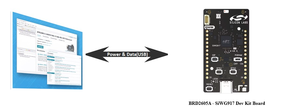
BRD2605A - SiWG917 Dev Kit Board (hereafter referred to as the dev kit board).
BRD2708A - SiWG917Y Explorer Kit (hereafter referred to as the explorer kit board).
If a radio board is used or if you need to measure power using the explorer kit board or dev kit board, a WPK board is also required:
BRD4002A - Si-MB4002A Wireless Pro Kit Mainboard (hereafter referred to as WPK board).
Windows/Linux/MacOS computer with a USB port.
Type C USB cable compatible with the computer's USB port (for example, type C to type A if the computer has a type A USB port).
Setup Software#
You may setup the following software in this section while waiting to receive the hardware:
Install Simplicity Studio#
This section describes the following installation methods for Simplicity Studio 6:
Install from Scratch when you are installing Simplicity Studio for the first time.
Upgrade from the Demo-only Studio Edition when you have previously run a Studio demo as described in Run the Demo with Simplicity Studio.
Install from Scratch#
Download the latest version of Simplicity Installer and follow the installation instructions.
During the installation, make the following selections:
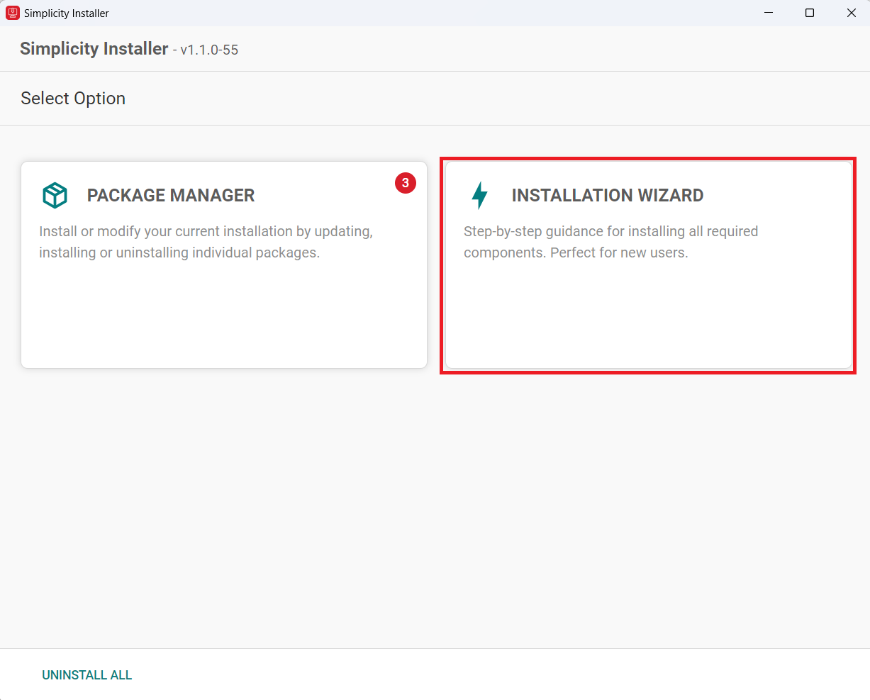
Select the INSTALLATION WIZARD option.
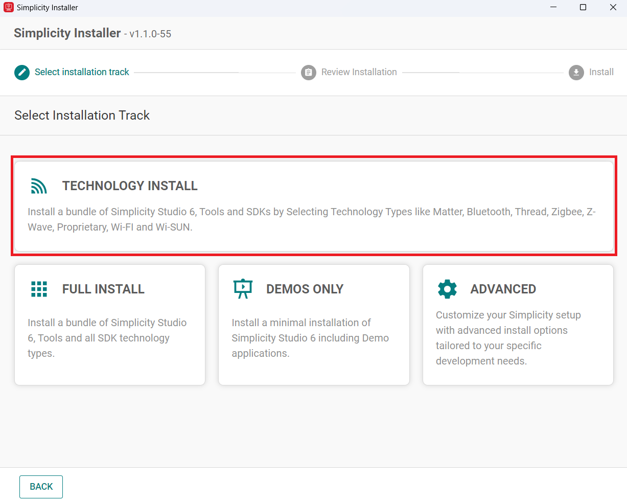
Select TECHNOLOGY INSTALL.
Select the Wi-Fi option.
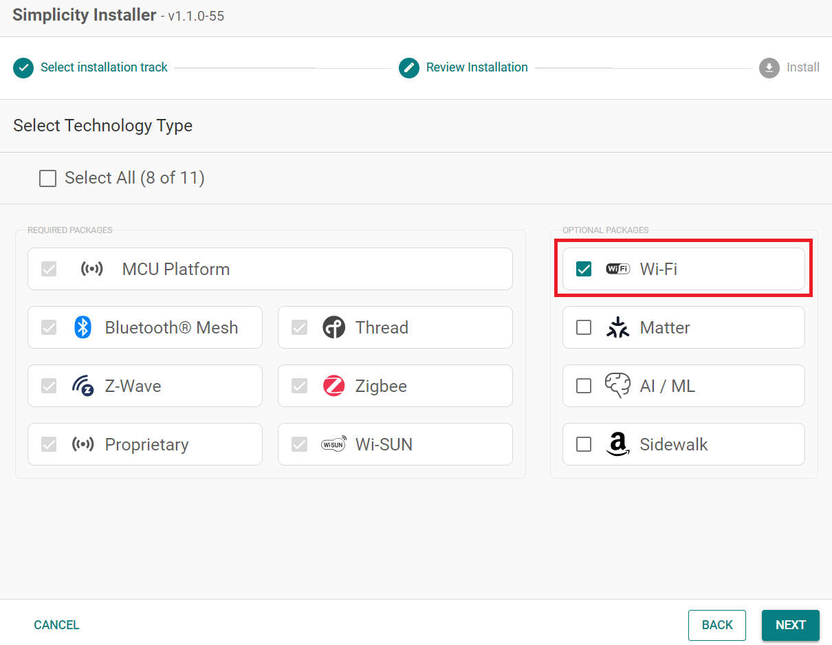
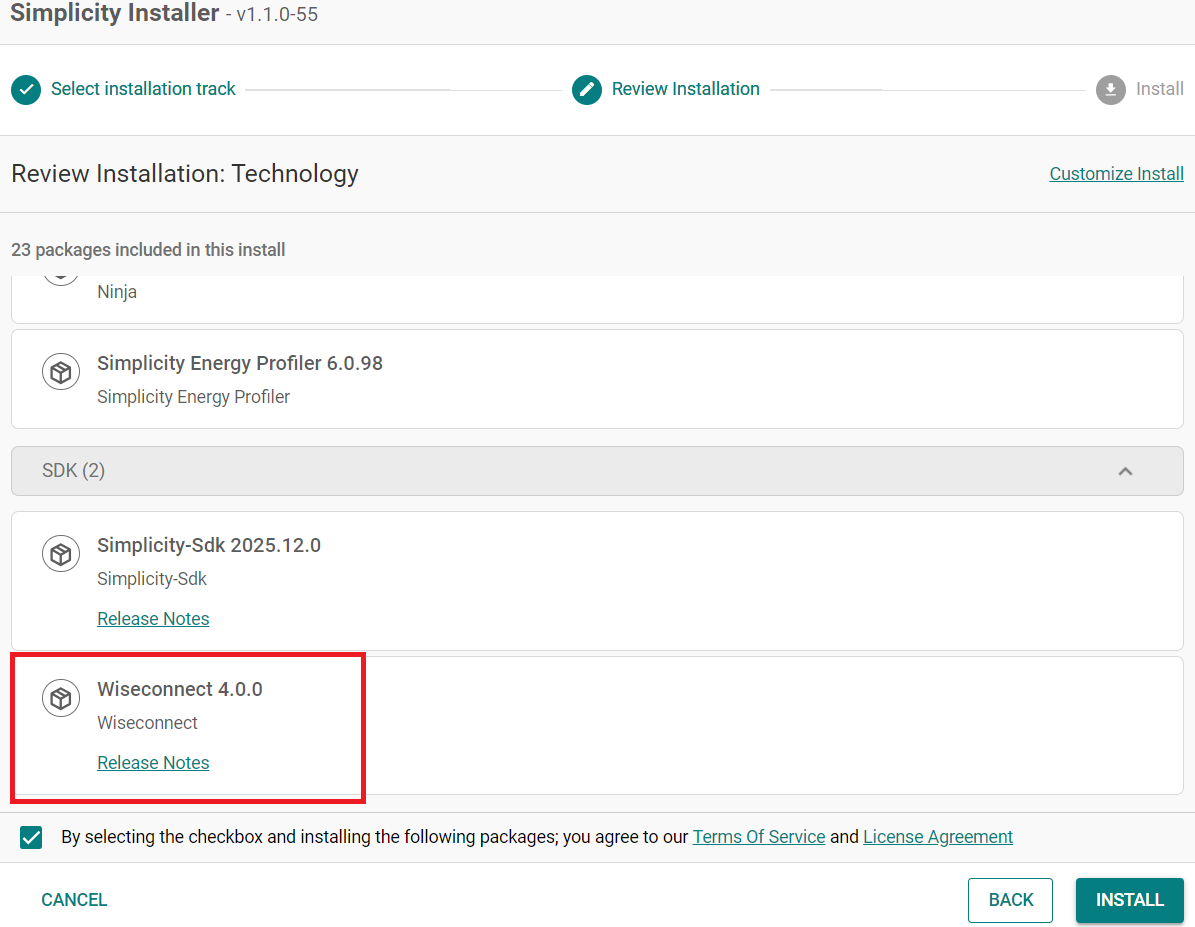
Click Next and make sure Wiseconnect is shown under the SDK that needs to be installed.
Upgrade from the Demo-only Studio Edition#
If you have installed the demo version using the option shown below:
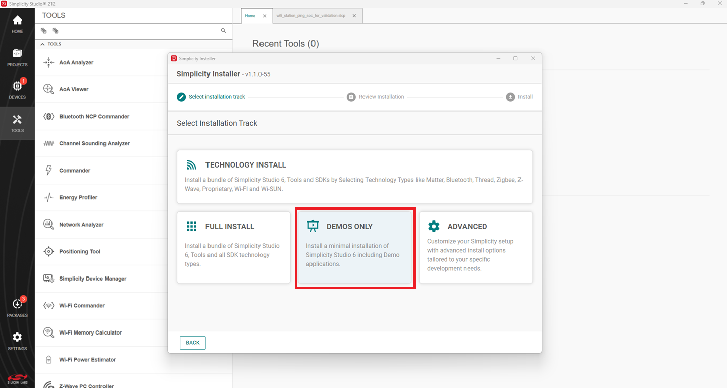
Continue from step 2 in the Install from Scratch section.
Install the GNU ARM v12.2.1 Toolchain#
Note: From v4.4.0 on, Simplicity SDK (SiSDK, formerly Gecko SDK/GSDK) requires v12.2.1 of the GNU ARM toolchain to compile a project successfully.
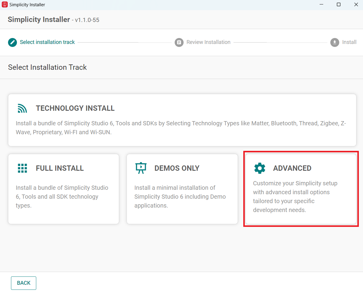
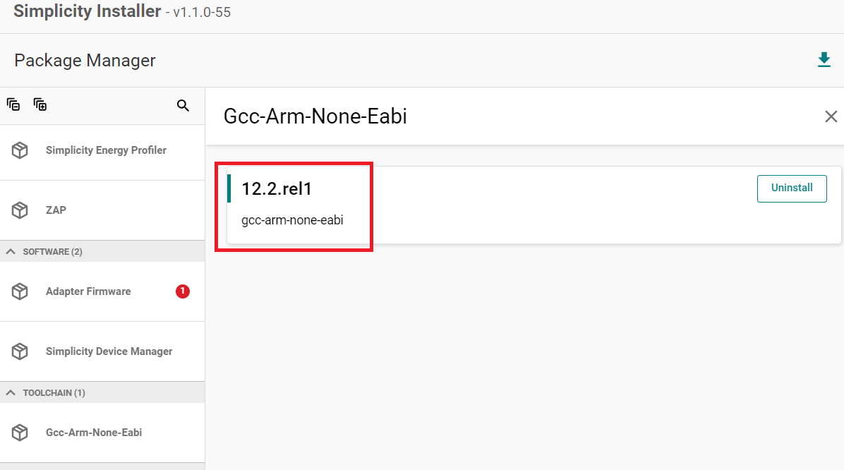
Launch the Simplicity Installer.
Click on the Advanced option.
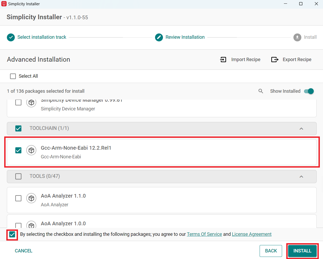
Select Gcc-Arm-None-Eabi 12.2.Rel1.
Check the box and click install.
Note: This is installed by default with the studio if you do a FULL INSTALL.
Note: If you have an existing project, see Silicon Labs community page for instructions on configuring the toolchain version in your project.
Install the WiSeConnect Extension#
If you already selected the WiSeConnect extension in the Install Simplicity Studio section, you may skip this section.
Before installing the WiSeConnect extension, upgrade to a compatible SiSDK (formerly GSDK) version if you have not already done so. See the Prerequisites section for the supported SiSDK (formerly GSDK) versions.
You can install WiSeConnect using one of the following methods:
Install from Scratch (recommended)
Install WiSeConnect from Settings#
Note: Make sure that you use SiSDK and WiSeConnect SDK versions from the same release. To determine which SiSDK and WiSeConnect SDK versions are in a particular release, see the Compatible Software section of Release Notes.
Download the WiSeConnect source code from the following URL after substituting x.x.x with the desired release version:
https://github.com/SiliconLabs/wiseconnect/archive/refs/tags/vx.x.x.zipIf you don't know your release version, go to the GitHub Releases Page and select the version to download.
Unzip the downloaded
wiseconnect-x.x.x.zipfile. It will be extracted into a folder structure similar to the following:wiseconnect-x.x.x |--- wiseconnect-x.x.x |------ <source code>Launch Simplicity Studio.
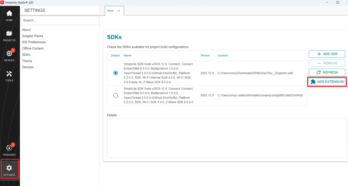
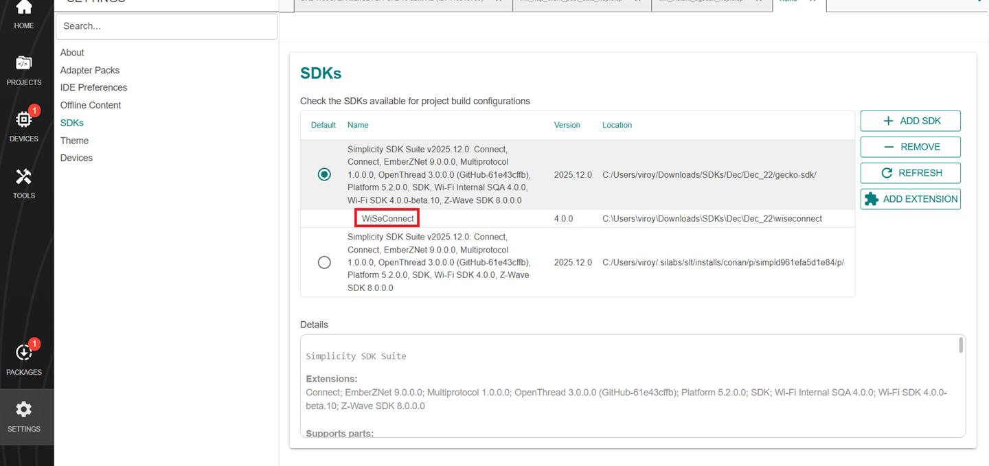
In the Simplicity Studio home page, go to SETTINGS and select the SDKs tab
Select Simplicity SDK (formerly Gecko SDK) Suite vx.x.x and click ADD EXTENSION.
In the Add SDK Extensions window, click Browse.
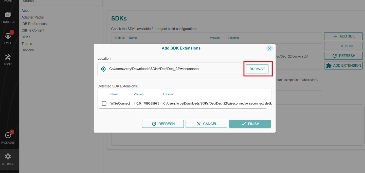
Locate and select the
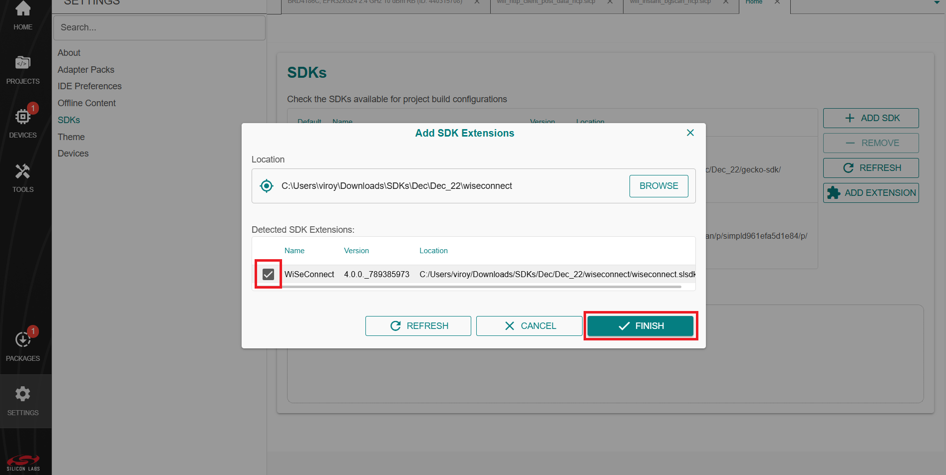
wiseconnect-x.x.xsub-folder extracted in step 2 above which contains the source code.Studio will detect the WiSeConnect SDK extension.
Select the detected extension and click FINISH.
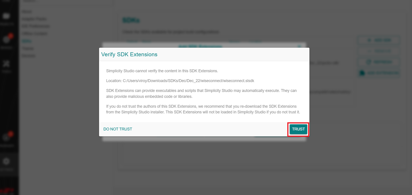
If a Verify SDK Extension pop-up is displayed, click Trust.
The selected WiSeConnect extension will be displayed.
Click REFRESH and navigate to HOME or PROJECTS.
Install the VS Code Extension#
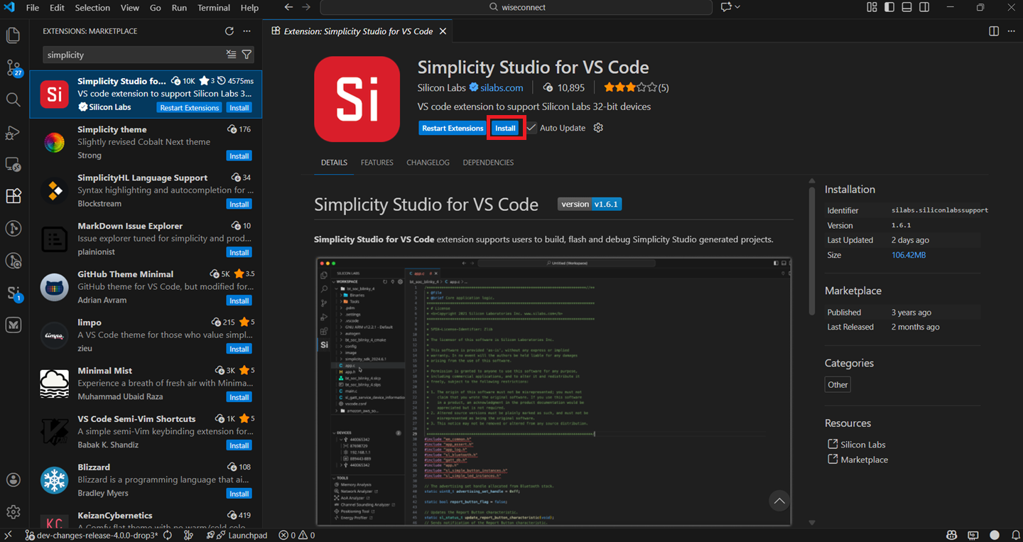
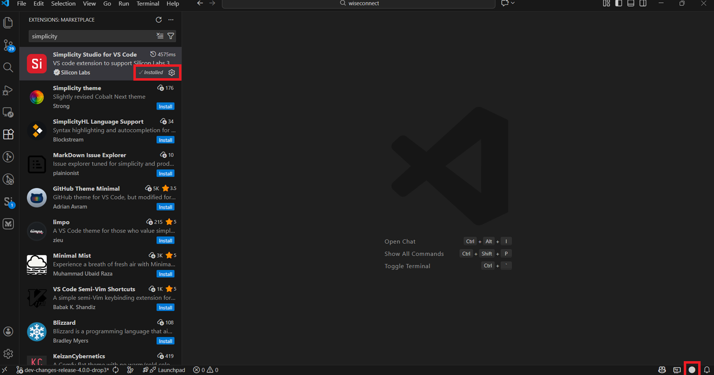
Navigate to the Extensions tab in VS Code and search for Simplicity Studio for VS Code extension.
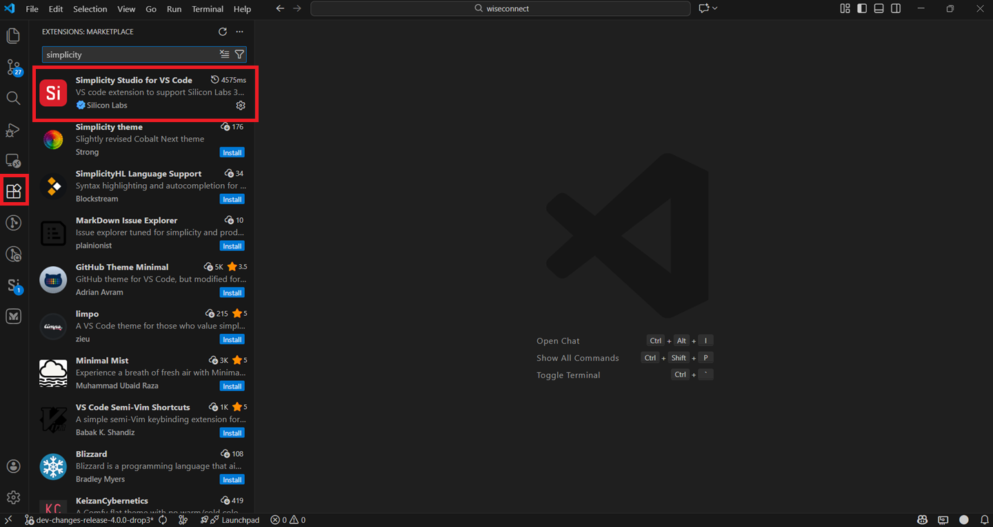
Install the extension.
Once the extension is installed and restarted, it will automatically detect the studio.
Note: This can be confirmed once the circle at the bottom right corner turns white.
Connect SiWx91x to Computer#
Connect the WPK board, explorer kit board, or dev kit board to your computer using a USB cable.
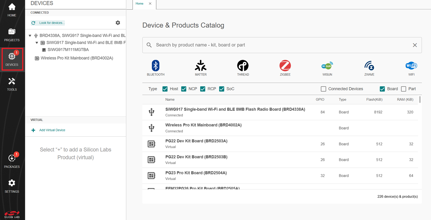
Navigate to the DEVICES tab.
Simplicity Studio will detect and display your SiWx917 board.
Note: See the troubleshoot a board detection failure section if Studio failed to detect your board.
Update SiWx91x Connectivity Firmware#
Note: The SiWx917 connectivity firmware version is tightly coupled with the WiSeConnect extension version. You must update the SiWx917 connectivity firmware when:
You first receive an SiWx917 Pro kit
You first receive an SiWx917 board, or
You upgrade or downgrade your WiSeConnect extension
You can update the SiWx91x connectivity firmware by using one of the following paths:
Update Firmware using Simplicity Studio Launcher#
Note: This method requires Simplicity Studio version SV5.9.0.1 or above.
Open Simplicity Studio and connect the SiWx91x to your computer.
Go to the DEVICES section.
Select your SiWx917 board from the displayed list.
The product information OVERVIEW tab is displayed.
Next to the Connectivity FW field, click Read FW Version.
A warning message is displayed.
Click Yes.
After you reset the connected SiWx91x board, the current firmware version appears next to the Connectivity FW field. If the firmware version is older than the version required by the installed WiSeConnect extension, an Update to xxxx option appears, where xxxx is the firmware version included with the WiSeConnect extension.
Note: If the firmware version matches the one required for your WiSeConnect extension, you will see the screen as described in step 13.
Click Update to xxxx.
The Connectivity Firmware Update Warning message is displayed.
Click Yes.
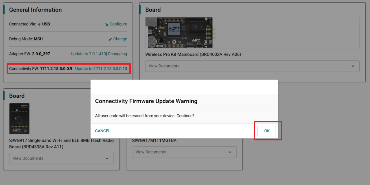
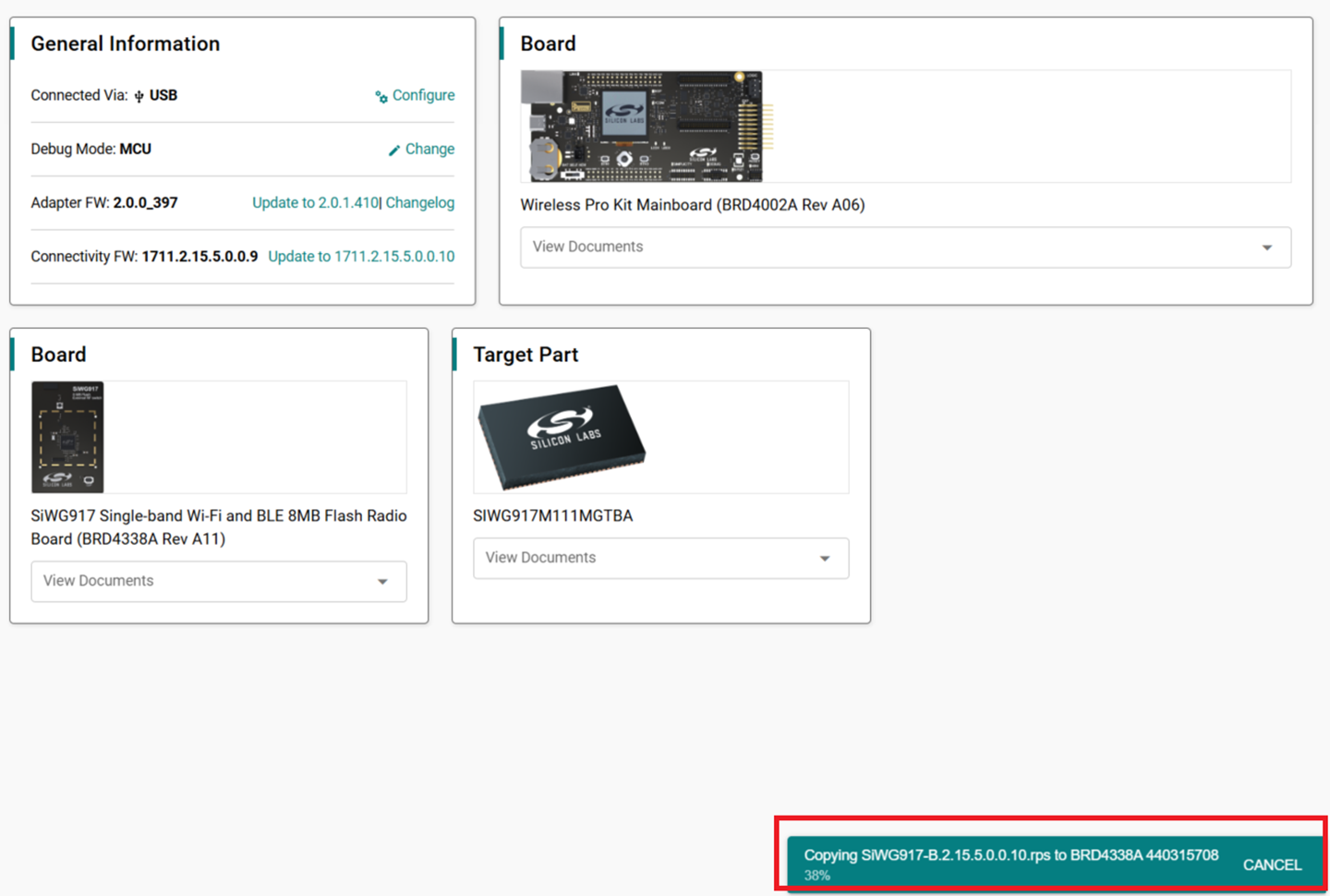
A progress message is shown.
On successful update, the updated firmware version appears next to the Connectivity FW field with the label
Latestnext to it. This label indicates that the SiWx917 connectivity firmware version now matches the one required for your installed WiSeConnect extension.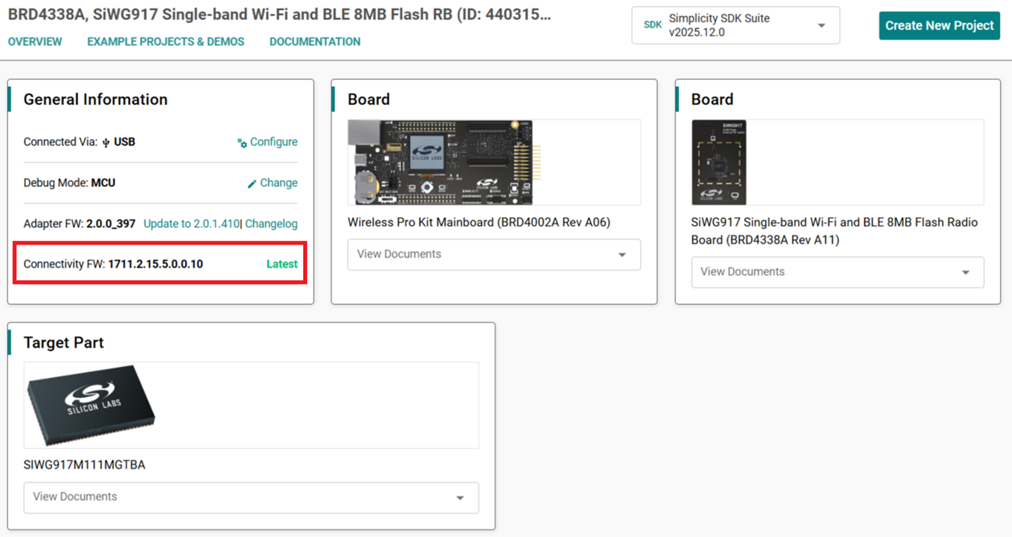
Note: See the troubleshoot a firmware update failure section in case of failure in updating the firmware.
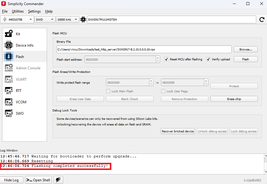
Update Firmware using Simplicity Commander#
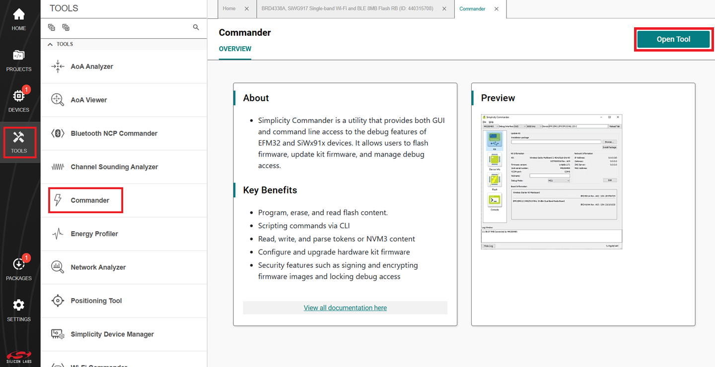
In the Simplicity Studio home page, click TOOLS.
In the TOOLS dialog, select Commander and click Open Tool.
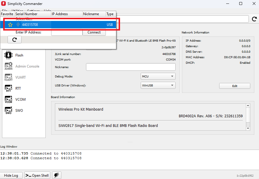
In the Commander window, click Select Kit and choose your SiWx917 board.
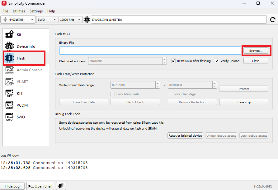
In the navigation pane, go to the Flash section.
Click Browse next to the Binary File field.
Locate and select the firmware file to flash from within the appropriate sub-folder of the WiSeConnect extension path:
For the OPNs SiWG917M110LGTBA, SIWG917Y110LGABA, and SIWG917Y110LGNBA, select the firmware file from the
connectivity_firmware/litesub-folder.For all other OPNs, select the firmware file from the
connectivity_firmware/standardsub-folder.
Note:
If you do not see any files in the sub-folder, select All files in the file filter field in the Browse dialog box.
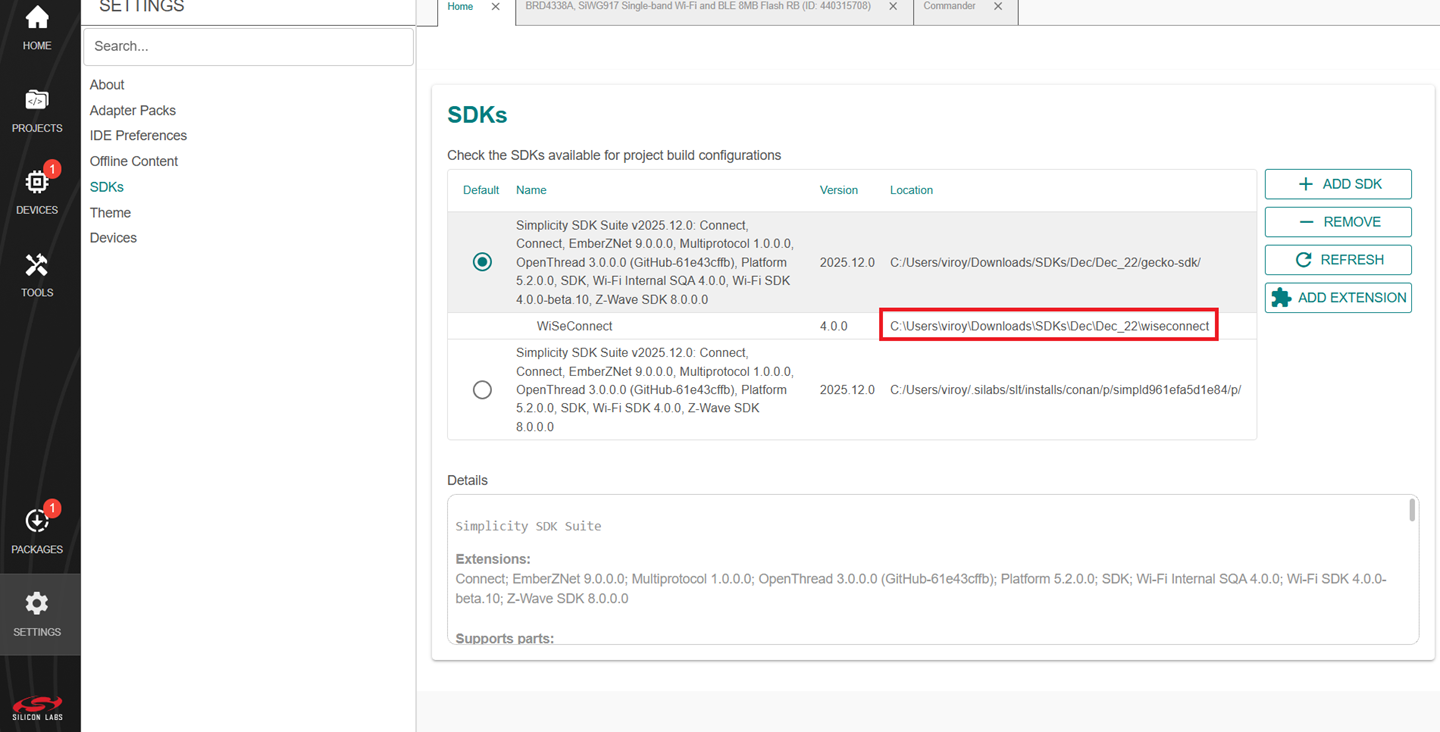
The WiSeConnect extension path is the one where the extension was downloaded during installation. If you are not sure what the path is, you may refer to the location in the SETTINGS > SDKs and click the installed Simplicity SDK.
Click Flash.
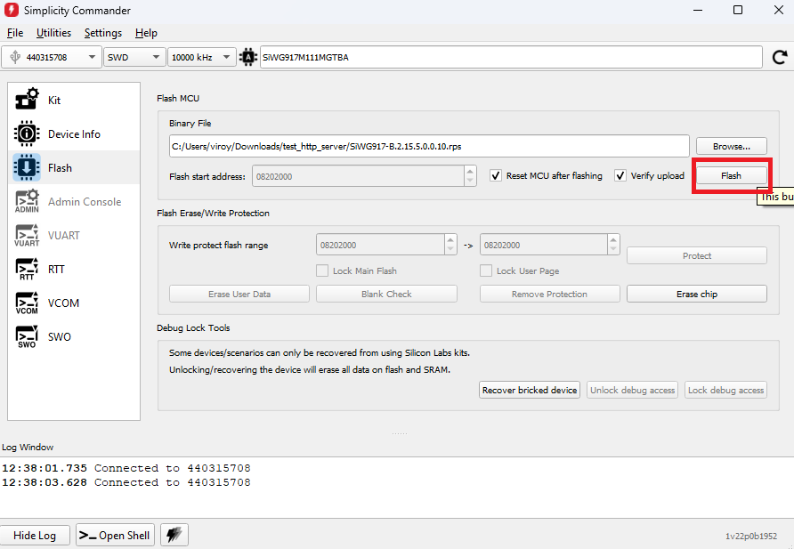
The firmware flashes and the Log Window displays the message: "Flashing completed successfully!"
Note: See the troubleshoot a firmware update failure section in case of failure in updating the firmware.
Create a Project#
Open Simplicity Studio and connect the SiWx91x to your computer.
Go to the DEVICES section.
Select SiWx917 board from the displayed list.
Note: If you do not have the SiWx917 board or you have not connected it to your computer, you can still create the example projects by following the procedure below:
Navigate to the DEVICES section.
Click on Add Virtual Device.
In the search bar, search for SiWG917 and click.

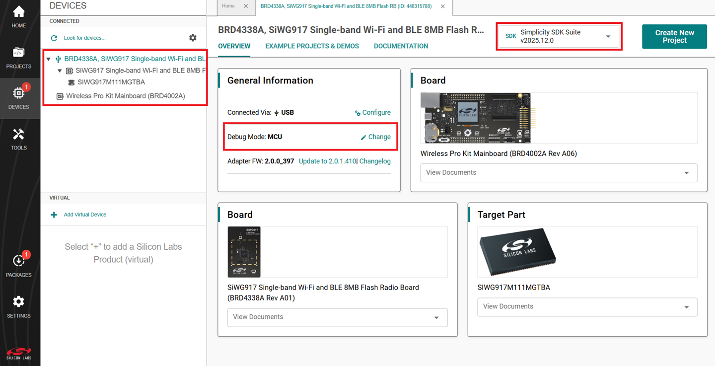
The Launcher page displays the selected board's details.
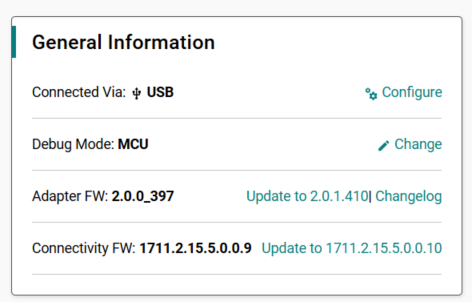
Select the OVERVIEW tab.
Verify the following in the General Information section:
The Debug Mode is Onboard Device (MCU).
The Preferred SDK is the version you selected earlier.
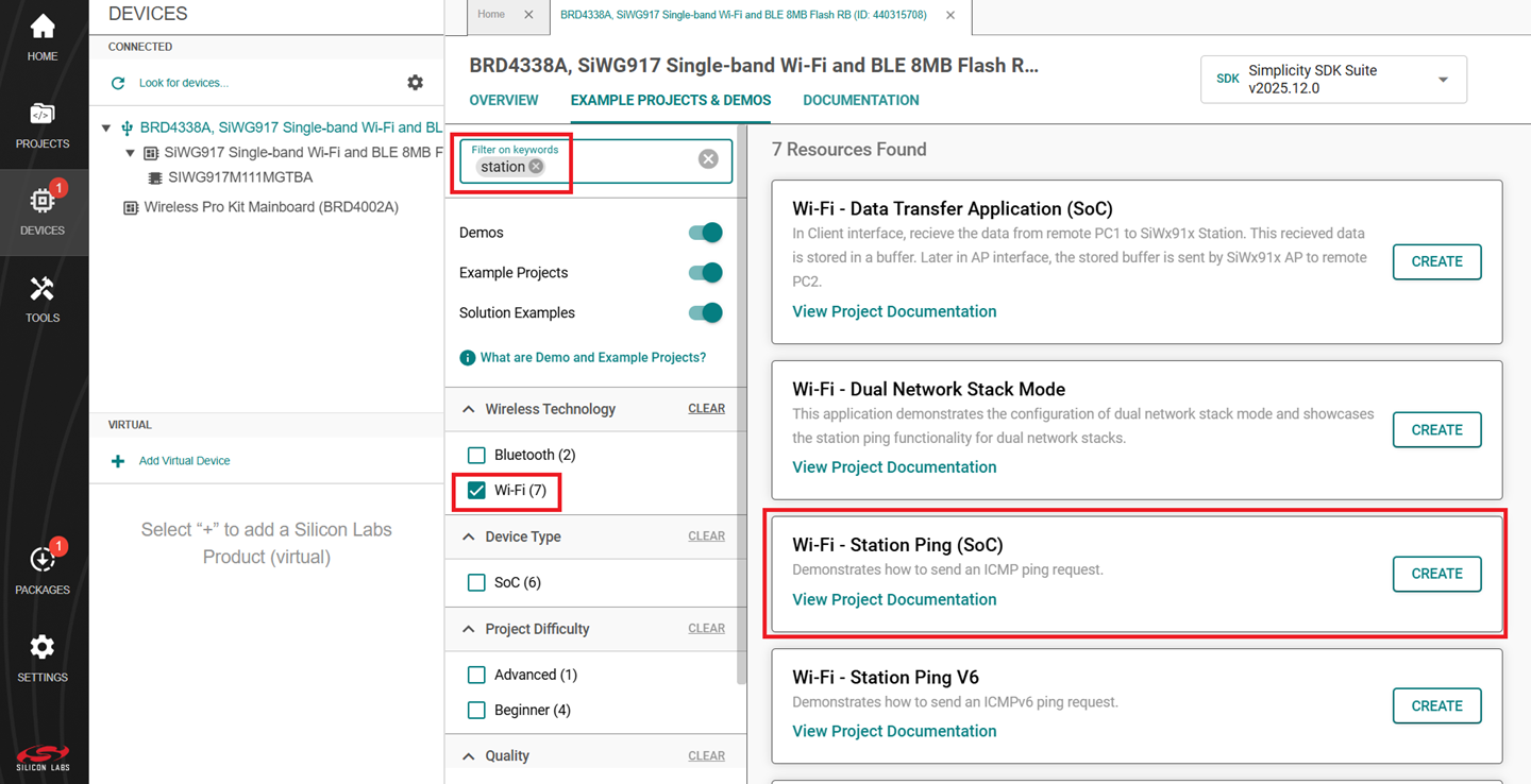
Select the EXAMPLE PROJECTS & DEMOS tab.
Locate the example you want and click CREATE.
Note: We recommend using the Wi-Fi - Station Ping (SoC) example with this guide.
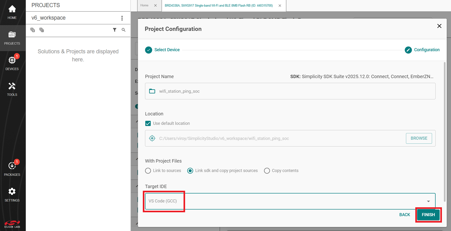
In the Project Configuration window, select the IDE as VS Code (GCC) and click FINISH.
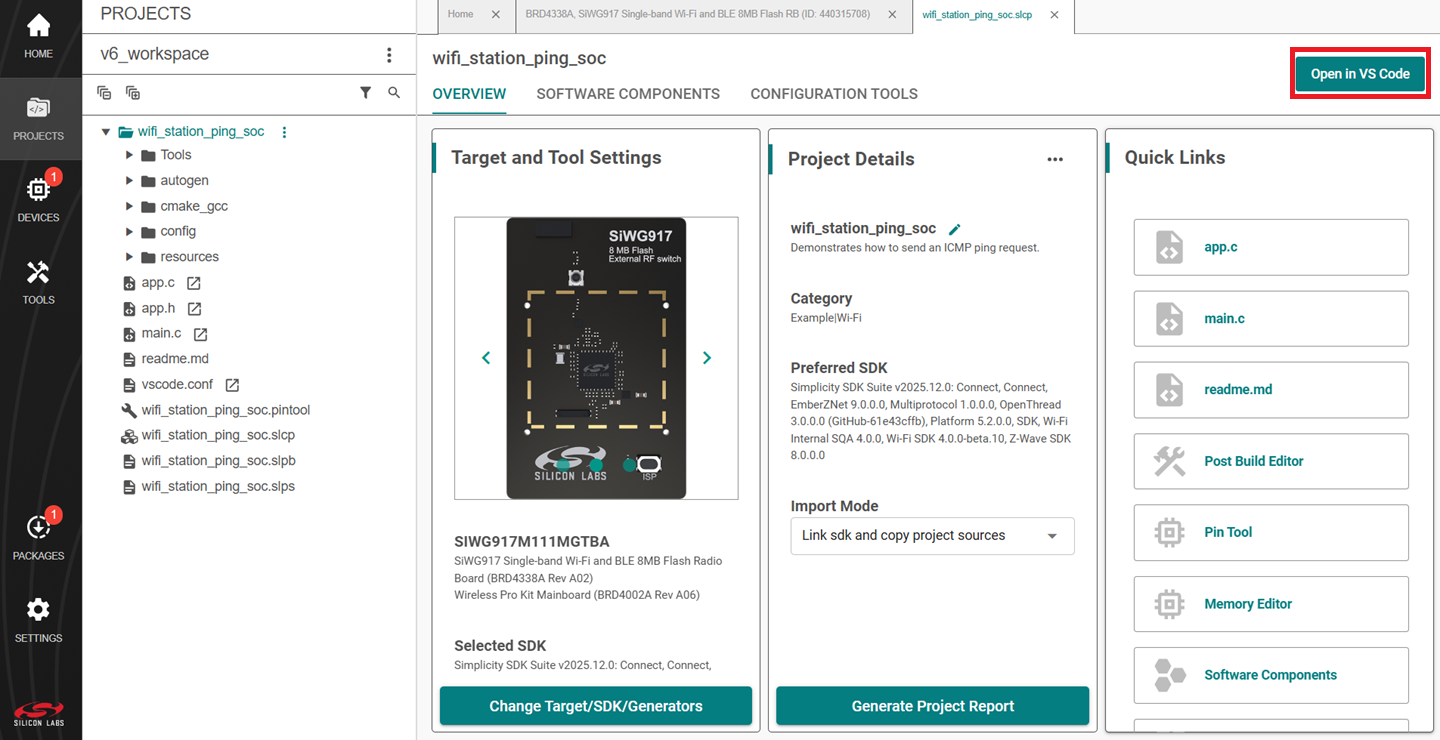
In the newly opened window, click on Open in VS Code option.
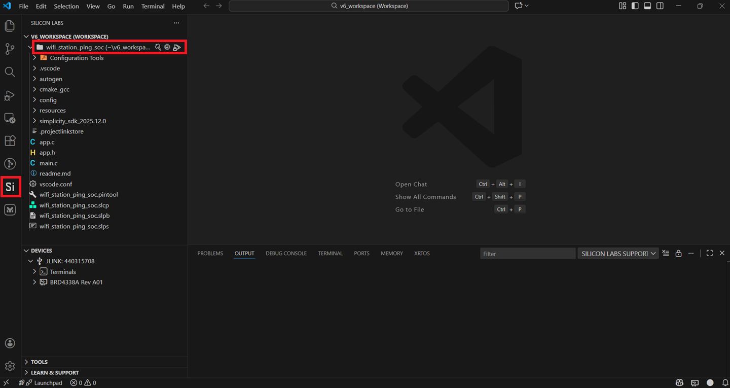
In VS Code, navigate to the Silicon Labs extension in the side panel.
Configure an Application#
Configure the settings for your example. For Wi-Fi - Station Ping (SoC) (the recommended example for this guide) or for other examples, see the Application Build Environment section in the README page for configuration instructions.
Note:
You may use the Component Editor to configure the components in your example.
You may use the Pintool to configure the pin mappings in your project for your SiWx917 system-on-chip.
Use the port macros from
sl_gpio_board.hrather than those auto-generated inpin_config.h.Edit the configuration in
RTE_Device_917.hto switch the GPIOs 64 to 75 between high power (HP) and ultra-low power (ULP).
Build an Application#
Note: If you upgraded from an SiSDK (formerly GSDK) version earlier than v4.4.0, you must upgrade your GNU ARM Toolchain. See the GNU ARM v12.2.1 Toolchain section.
Launch Simplicity Studio.
Open the project in VS Code IDE following the procedure mentioned in Create a Project step 10.
Right click on the project and click Build.
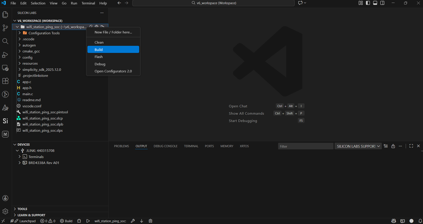
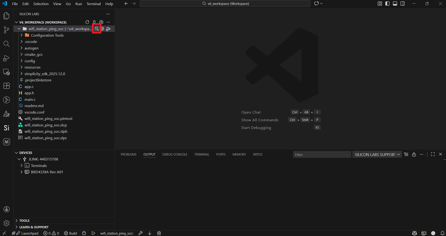
You may also directly click the Build button with a hammer icon on the project options as an alternative.
Note: See the troubleshoot an application build section in case of failure in building the application.
Console Input and Output#
Connect your WPK board to your computer.
Open Simplicity Studio.
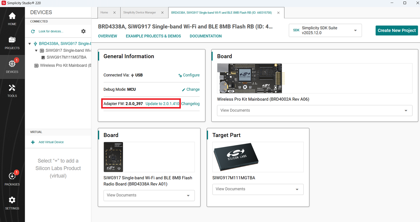
In the DEVICES pane, select your WPK board.
The Adapter FW field shows your WPK board's current firmware version, similar to 2vnpxxbyyy, where n is the major version, xx is the patch version number, and yyy is the build number.
Click Update to 2.0.xx.yyyy.
The firmware upgrade on your WPK board.
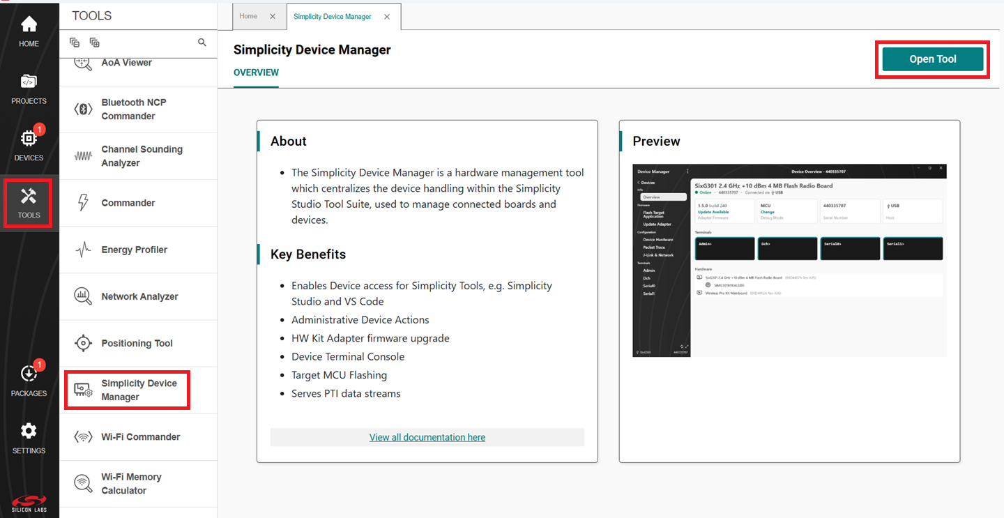
Navigate to the TOOLS pane, click on Simplicity Device Manager, and click Open Tool.
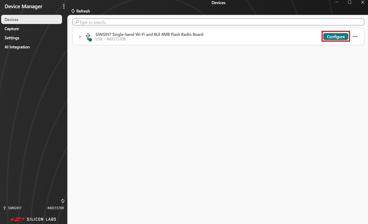
Click on the Configure option.
Click on the Serial 1 tab.
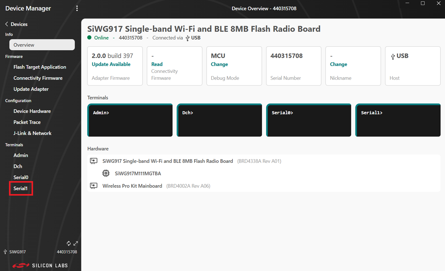
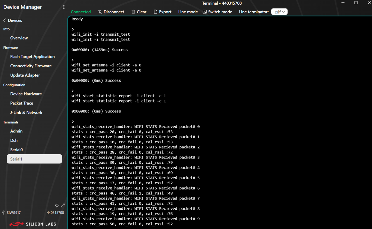
Console output displays in the Serial 1 tab.
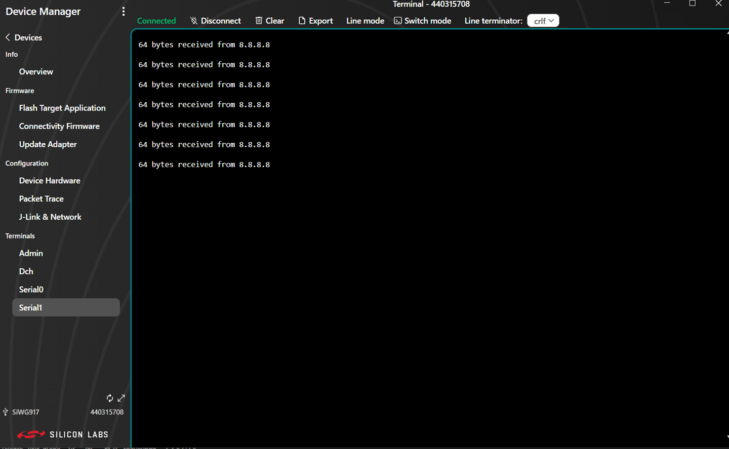
You can enter console input and send it to the device.
Flash an Application#
Note: The SiWx91x SoC comes pre-flashed with a bootloader. A bootloader image does not need to be flashed separately.
The following are two alternative methods to flash an application to the application processor of the SiWx91x device:
Once you flash the Wi-Fi - Station Ping (SoC) example (the recommended example for this guide), you may refer to the Test the Application section of its README page to explore its output. The other sections of the README such as the Purpose/Scope section and Overview section (not present in some README files) provide more information about the example.
See the Examples page to explore all available examples and view their README pages.
Flash an Application Built Using Simplicity Studio#
Build the application as described in the Build an Application section.
In the project pane, right-click on your project name and click on Flash.
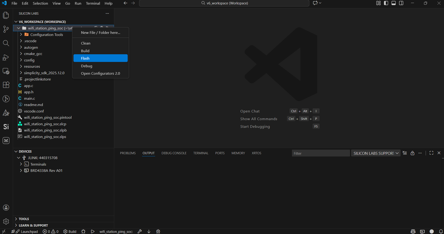
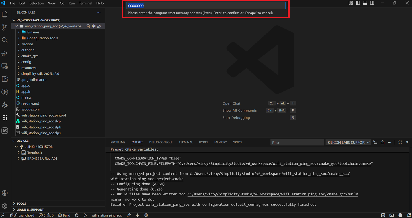
Users are prompted to click on one of the following binary formats. (For this guide, we will follow the binary with .rps format).
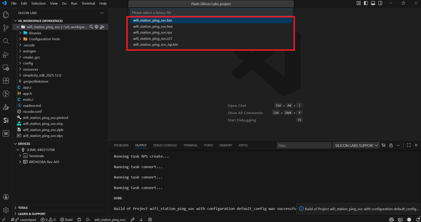
Click Enter if the option below is displayed.
Once Flashing is successful, the terminal dispalys the output as below.
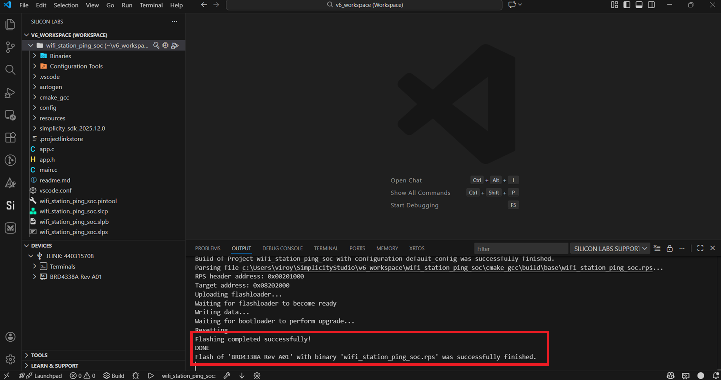
View the standard output or enter input data as needed. See the Console Input and Output section.
Note: See the troubleshoot an application flash failure section in case the application fails to flash.
Flash an Application Binary#
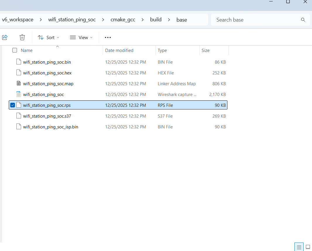
If you build the binary as described in the Build an Application section, the build process generates a .rps file. The file is located under cmake_gcc > build > base in the user workspace.
Alternatively, you might receive a .rps file from another source, such as a colleague who built the binary and shared it with you.
The instructions to flash the application binary are almost the same as those for flashing an SiWx91x firmware file, except for the point mentioned further:
Instead of choosing the SiWx91x firmware file, select the
.rpsyou obtained in step 1 above.
Note:
If you do not see
.rpsfiles in the sub-folder, select All files in the file filter field in the Browse dialog box.
Note: See the troubleshoot an application flash failure section in case the application fails to flash.
Run the Application#
Once you flash the example, you may refer to the Test the Application section of its README page to explore its output.
The other sections of the README such as the Purpose/Scope section provide more information about the example.
See the Examples page to explore all available examples including their supported host interfaces (SPI and/or UART) and to view their README pages.
Note: See the troubleshoot an application run failure section in case the application fails to run.
Enable Additional Logs#
This section provides instructions to capture additional logs to help in troubleshooting application issues. The captured logs provide information about the data exchanged between the application processor and network wireless processor on the SiWx91x chipset.
Open your project in Simplicity Studio.
Navigate to the following path in the project folders:
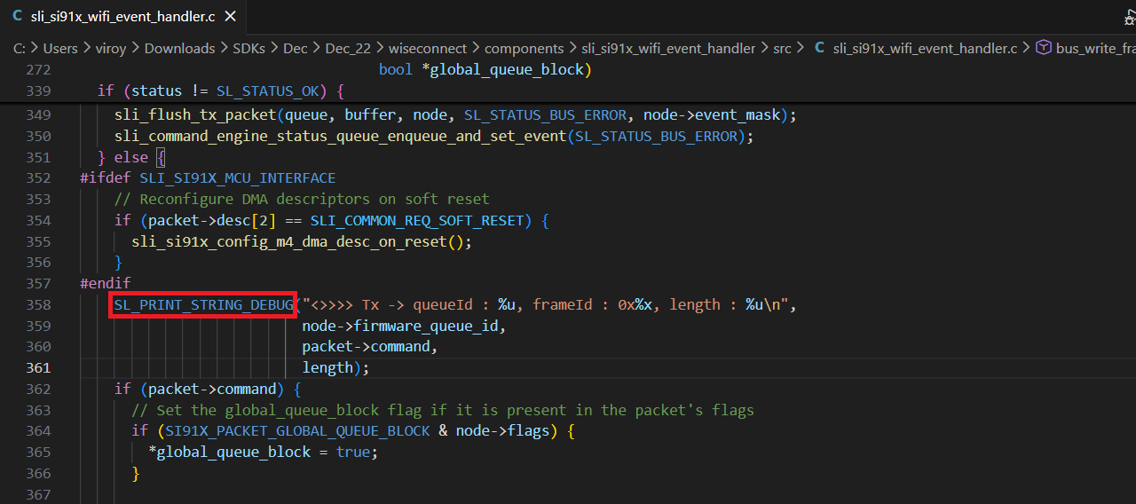
components/sli_si91x_wifi_event_handler/srcOpen the file
sli_si91x_wifi_event_handler.c.Make the changes illustrated below and save these changes.
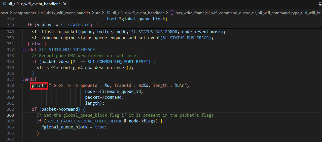
Replace the
SL_PRINT_STRING_DEBUGwithprintfin the following line for Tx communication to the network wireless processor from the application processor.
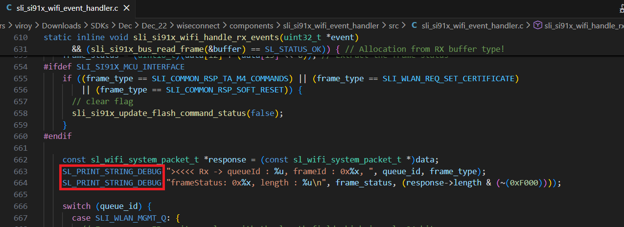
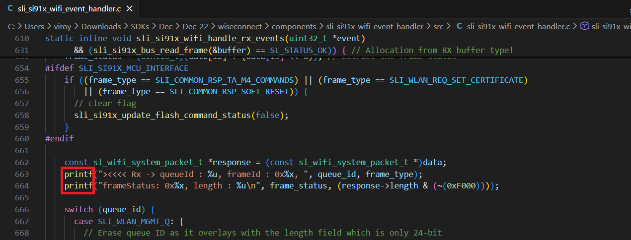
Replace the
SL_PRINT_STRING_DEBUGwithprintfin the below lines for Rx communication from Network wireless processor to Application processor.
Additional logs are displayed similar to the example below. Commands from the application to the network processor are shown beginning with
<>>>> Tx, while responses/events from the network to application processor are shown beginning with><<<< Rx:queueIdrepresents the internal command queue used in the SDK.frameIdrepresents the type of command (such as join or scan). Ideally, aTxframeId will have a matchingRxframeId representing the response to the command.frameStatusrepresents the success/failure code returned from the command. A value of0x0indicates success while a non-zero value indicates an error. See the Status Codes section for details.lengthrepresents the length of the packet.
><<<< Rx -> queueId : 4, frameId : 0x89, frameStatus: 0x0, length : 0 <>>>> Tx -> queueId : 4, frameId : 0x10, length : 40 ><<<< Rx -> queueId : 4, frameId : 0x10, frameStatus: 0x0, length : 0 <>>>> Tx -> queueId : 4, frameId : 0xc7, length : 3 ><<<< Rx -> queueId : 4, frameId : 0xc7, frameStatus: 0x0, length : 0 <>>>> Tx -> queueId : 4, frameId : 0xc8, length : 12 ><<<< Rx -> queueId : 4, frameId : 0xc8, frameStatus: 0x0, length : 0 <>>>> Tx -> queueId : 4, frameId : 0x11, length : 1 ><<<< Rx -> queueId : 4, frameId : 0x11, frameStatus: 0x0, length : 0 <>>>> Tx -> queueId : 4, frameId : 0x12, length : 0 ><<<< Rx -> queueId : 4, frameId : 0x12, frameStatus: 0x0, length : 6 <>>>> Tx -> queueId : 4, frameId : 0x1d, length : 4 ><<<< Rx -> queueId : 4, frameId : 0x1d, frameStatus: 0x0, length : 1 <>>>> Tx -> queueId : 4, frameId : 0xbe, length : 4 ><<<< Rx -> queueId : 4, frameId : 0xbe, frameStatus: 0x0, length : 0 <>>>> Tx -> queueId : 4, frameId : 0xa0, length : 1 ><<<< Rx -> queueId : 4, frameId : 0xa0, frameStatus: 0x0, length : 2 Wi-Fi client interface up success <>>>> Tx -> queueId : 4, frameId : 0xea, length : 8 ><<<< Rx -> queueId : 4, frameId : 0xea, frameStatus: 0x0, length : 0 <>>>> Tx -> queueId : 4, frameId : 0x13, length : 50 ><<<< Rx -> queueId : 4, frameId : 0x13, frameStatus: 0x0, length : 54 <>>>> Tx -> queueId : 4, frameId : 0xa5, length : 99 ><<<< Rx -> queueId : 4, frameId : 0xa5, frameStatus: 0x0, length : 0 <>>>> Tx -> queueId : 4, frameId : 0x14, length : 117 ><<<< Rx -> queueId : 4, frameId : 0x14, frameStatus: 0x0, length : 1 <>>>> Tx -> queueId : 4, frameId : 0x41, length : 59 ><<<< Rx -> queueId : 4, frameId : 0x41, frameStatus: 0x0, length : 18 Wi-Fi client connected <>>>> Tx -> queueId : 4, frameId : 0x29, length : 22 ><<<< Rx -> queueId : 4, frameId : 0x29, frameStatus: 0x0, length : 20 64 bytes received from 8.8.8.8 <>>>> Tx -> queueId : 4, frameId : 0x29, length : 22 ><<<< Rx -> queueId : 4, frameId : 0x29, frameStatus: 0x0, length : 20
Debug an Application#
Note: The steps below are instructions to debug using Simplicity Studio VS Code IDE. If you prefer to use the Ozone tool for debugging, follow the instructions in the Debug an Application with Ozone section.
Right-click on the project name and click Debug.
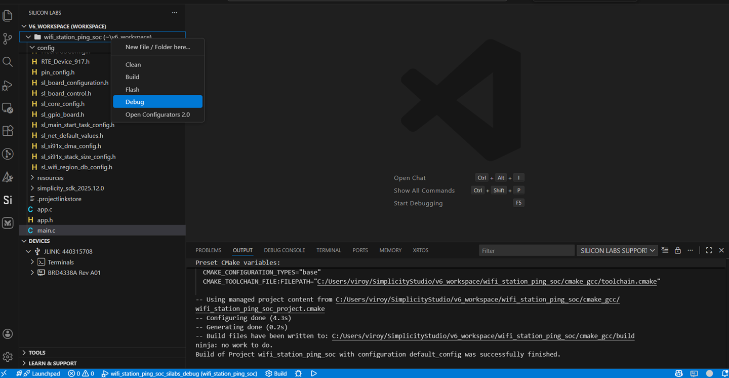
Studio switches to debug mode and halts execution at the
main()function in your application.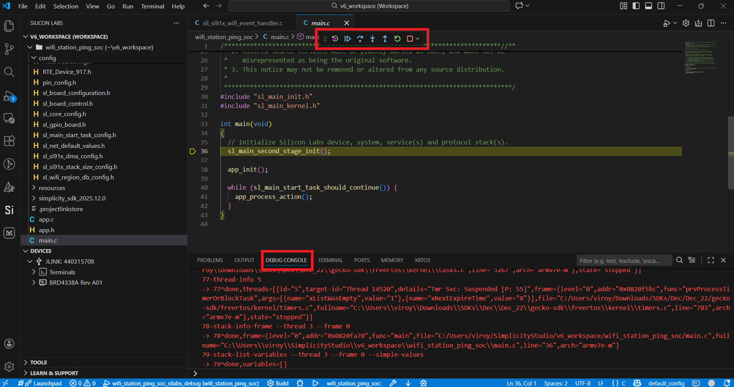
Add break points at the desired location of the code and click the Resume button (an icon with a rectangular bar and play button).
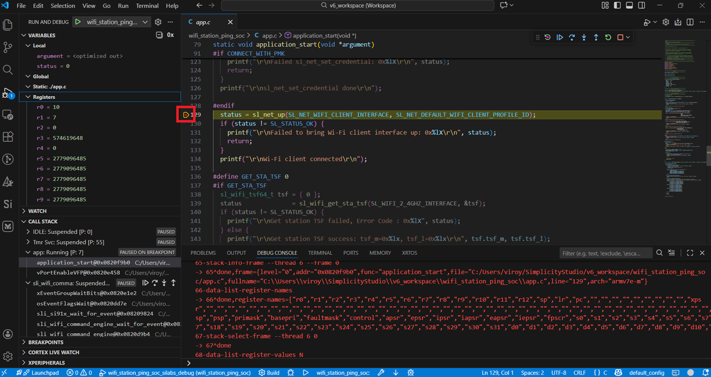
Execution halts at the break point.
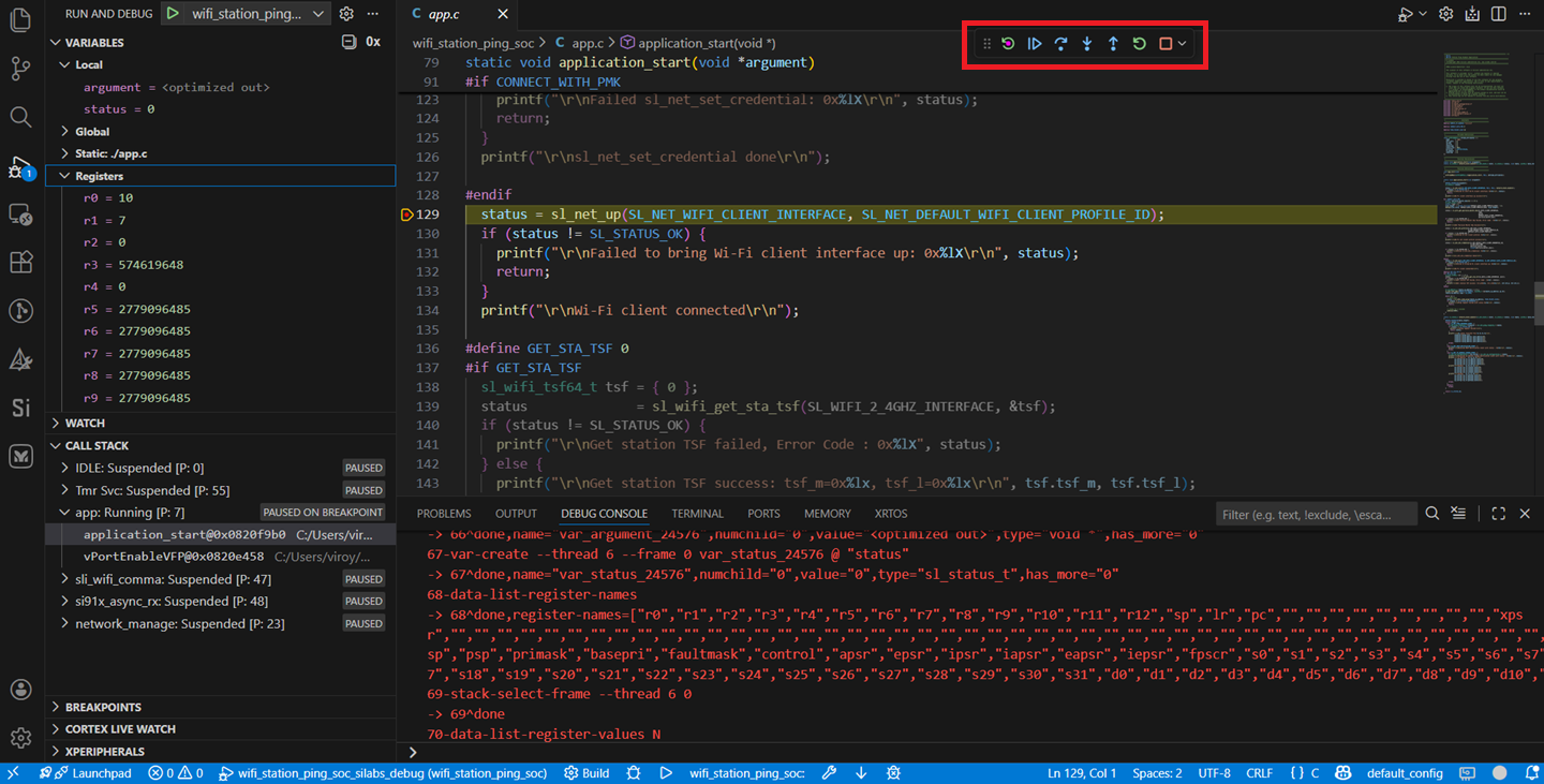
Use the following debug functions to direct the execution of the code:
Step Into button (an icon with an arrow pointing down to a dot).
Step Over button (an icon with an arrow going over a dot).
Step Out button (an icon with an arrow pointing out from a dot).
View the standard output or enter input data as needed. See the Console Input and Output section.
Note: See the troubleshoot an application debug failure section if the application fails to flash.
Debug an Application with Ozone#
This section contains alternative instructions for debugging, using the Ozone tool instead of Simplicity Studio.
Configure Ozone#
Navigate to the folder path
resources/ozone_configunder your WiSeConnect extension path.Note:
You must upgrade to WiSeConnect extension version 3.3.2 or later to see the above path. If you want to use an older extension version, you can download the
siwx917.jdebugandsiwx917.svdfiles directly from the Github repo.If you are not sure what the path is, refer to the location in the SETTINGS > SDKs page shown by clicking the Simplicity SDK Suite.
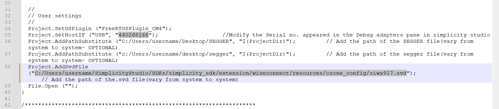
Open the Ozone configuration file
siwx917.jdebug.Update the absolute path to the
siwx917.svdfile next toProject.AddSvdFile.Note: If you are using WiSeConnect extension version 3.3.2 or later, the
siwx917.svdfile is located in the same folder assiwx917.jdebug.Update the serial number of your SiWx917 part next to
Project.SetHostIF.The serial number is shown in Simplicity Studio in the DEVICES tab when you plug in your device.
Debug with Ozone#
Update the connectivity firmware image that you intend to debug.
Flash the application binary that you intend to debug.
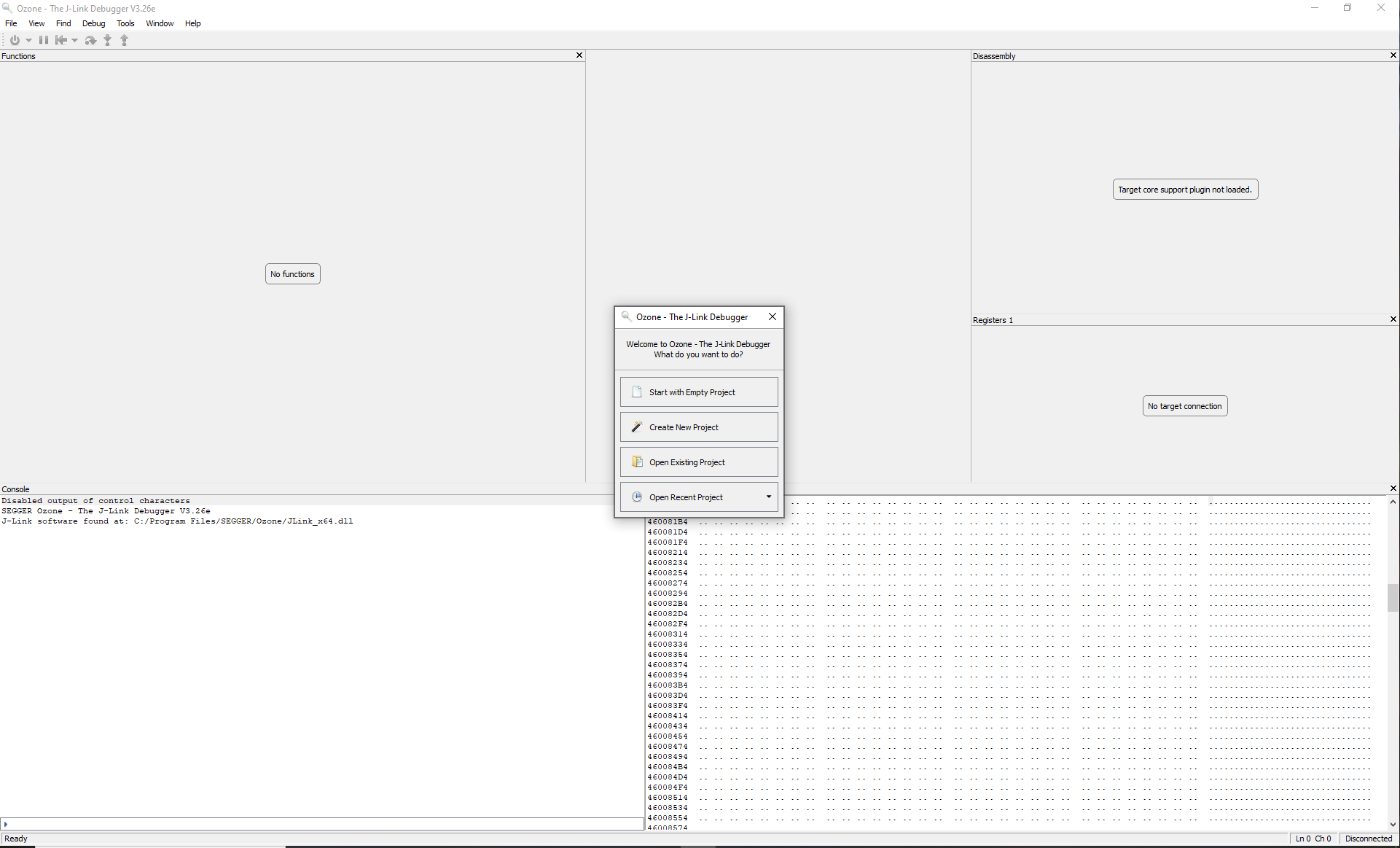
Download and launch Ozone.
Ignore the following window if it is displayed.
Select File > Open....
Navigate to and select the configured
siwx917.jdebugfile.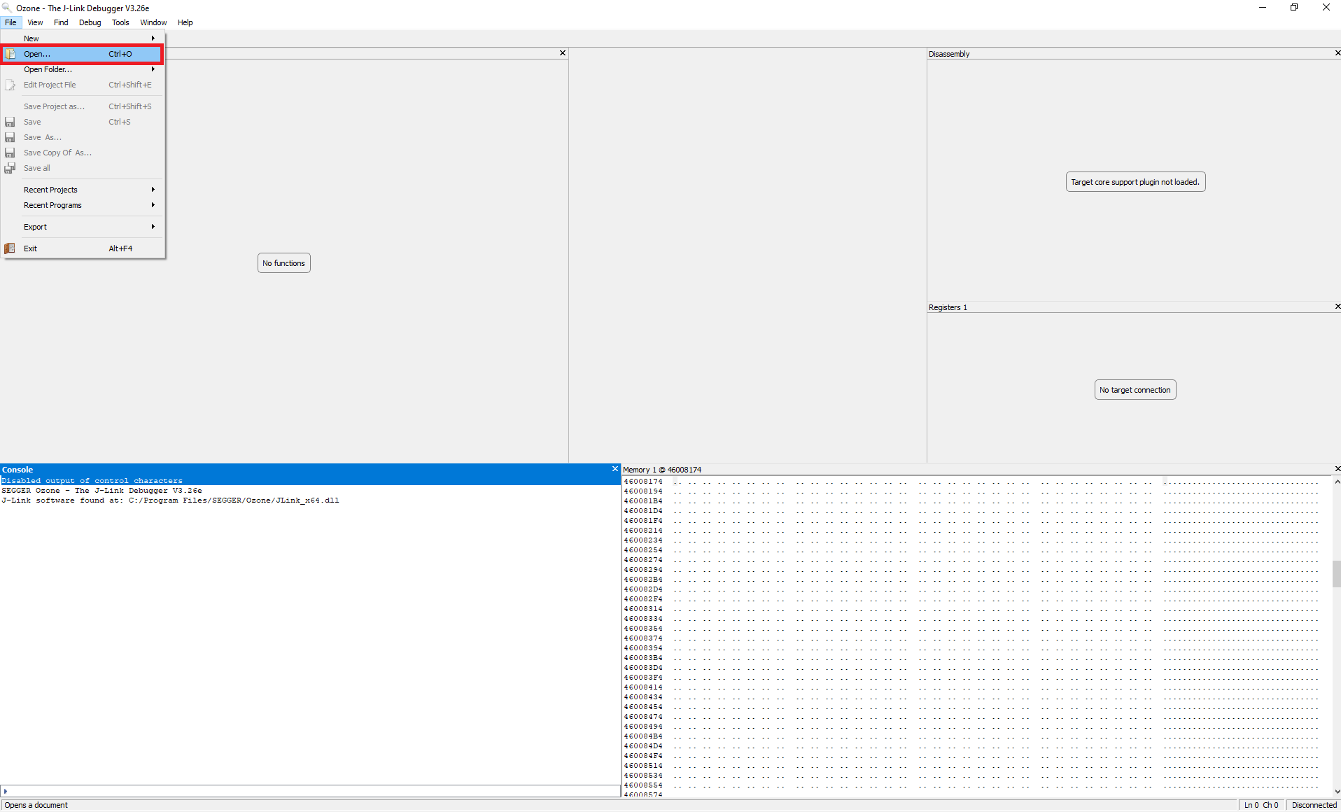
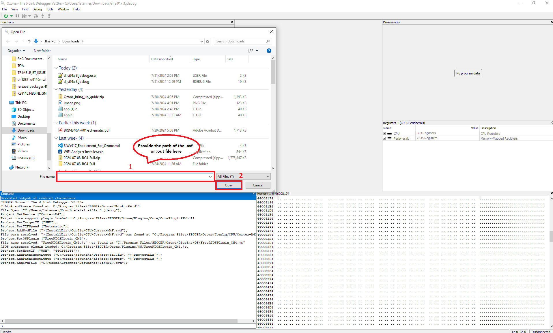
The Open File window displays for opening the application binary file.
Navigate to and select either the .axf or the .out application binary file generated when building your Simplicity Studio project.
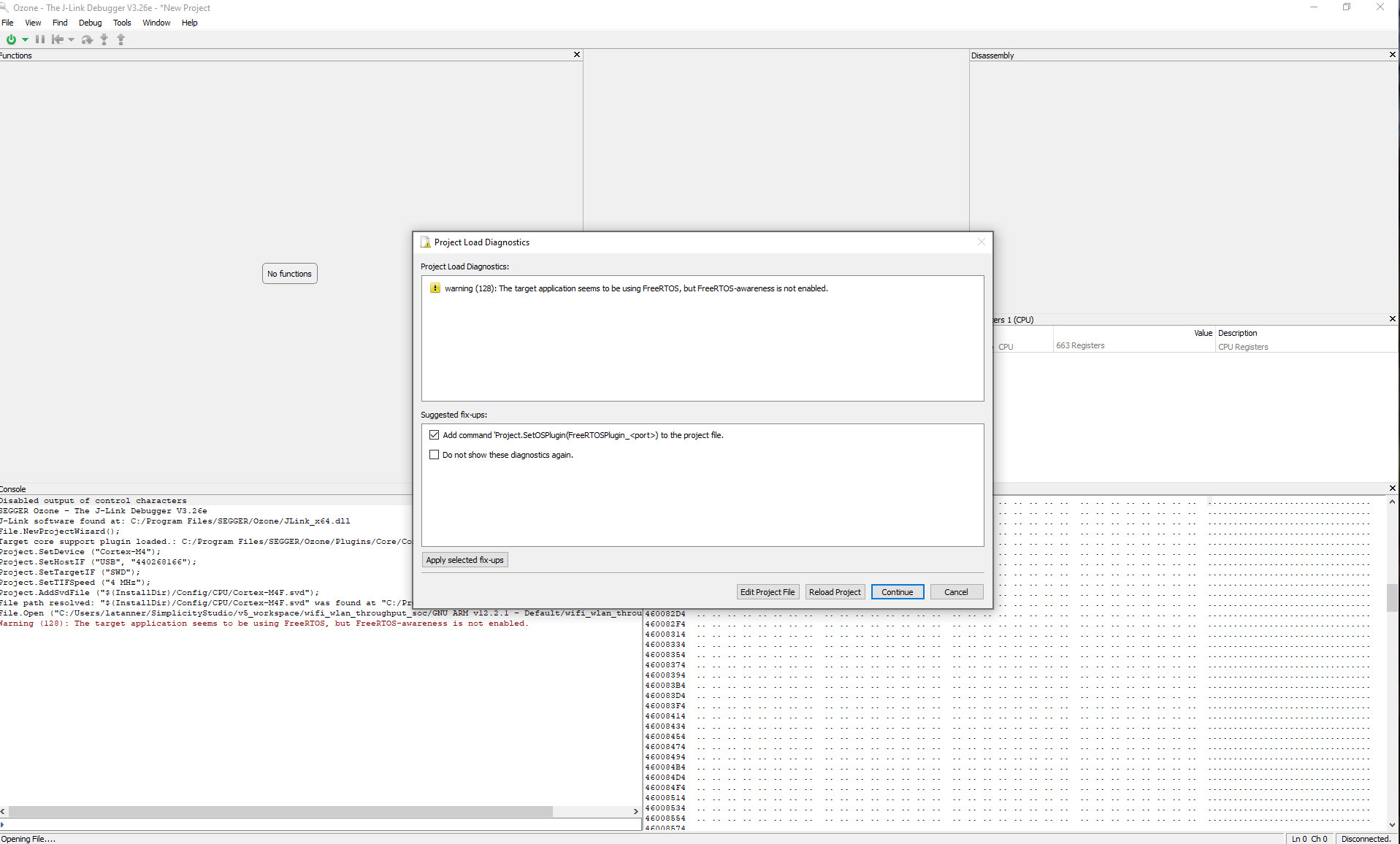
Click Continue on the Project Load Diagnostics warning window if it is displayed.
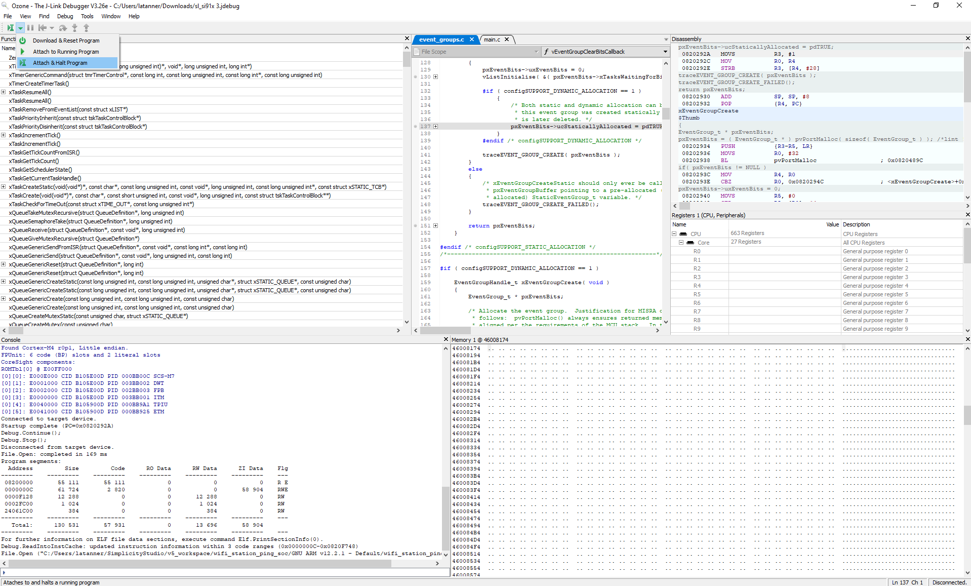
Select Attach & Halt Program in the dropdown next to the Power button on the top left-hand corner of the screen.
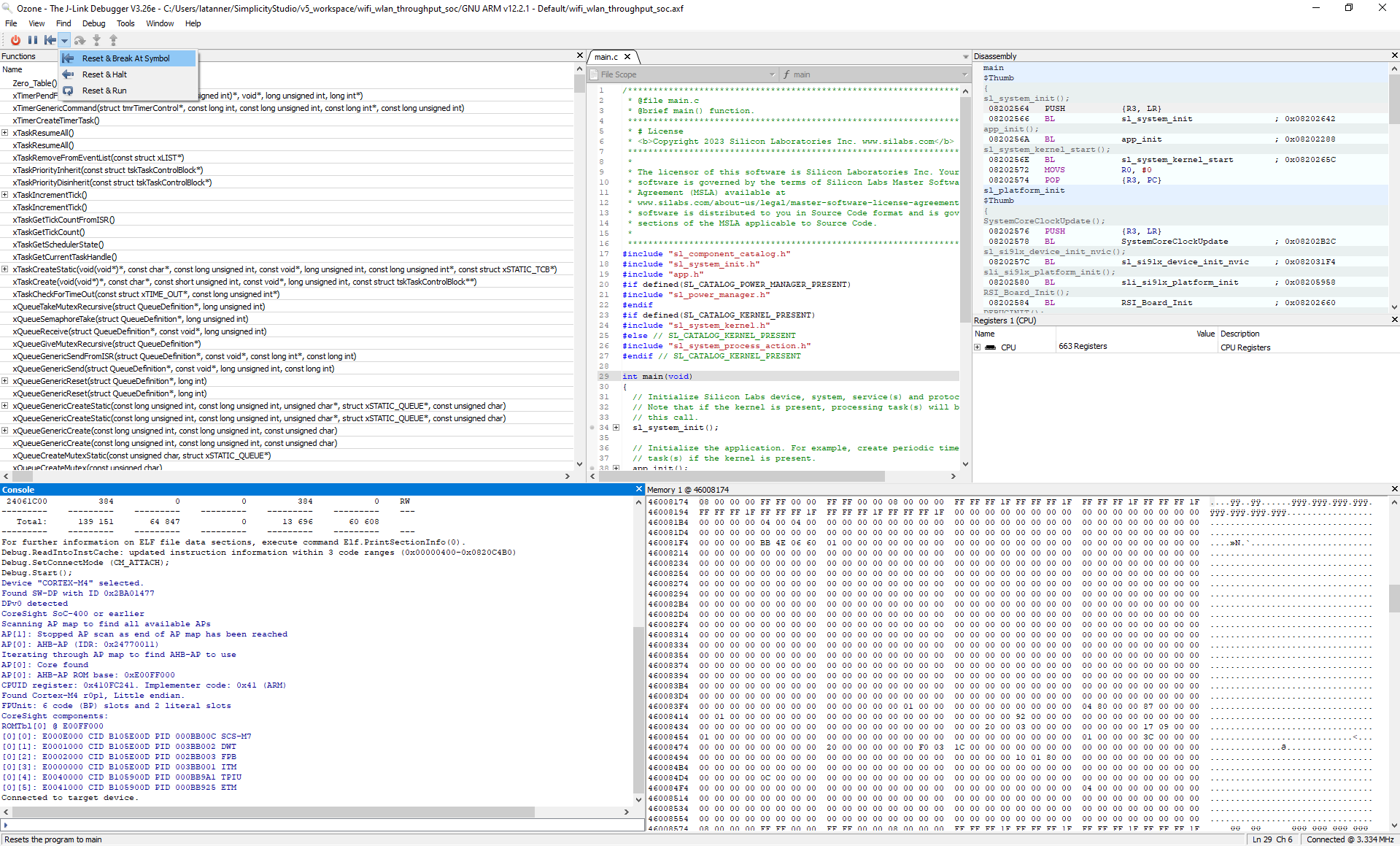
Select Reset & Break At Symbol in the dropdown next to the Play/Pause button on the top left-hand corner of the screen.
The attached SiWx917 device will reset.
To run the application, click the Resume/Halt button next to the Power button on the top left-hand corner of the screen.
Customize Application Components#
Simplicity Studio allows you to add or remove functional components in your application, such as BSD Sockets.
Note: For information about the functional components available with WiSeConnect SDK, see the Application Components section.
Add a Component#
In the PROJECTS pane, double-click the project_name.slcp file.
Select the SOFTWARE COMPONENTS tab.
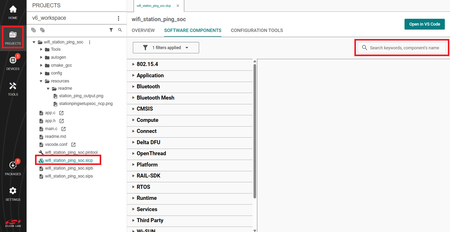
Select the SDK Extensions filter.
Browse or search for and select the component that you want to install.
Click Install.
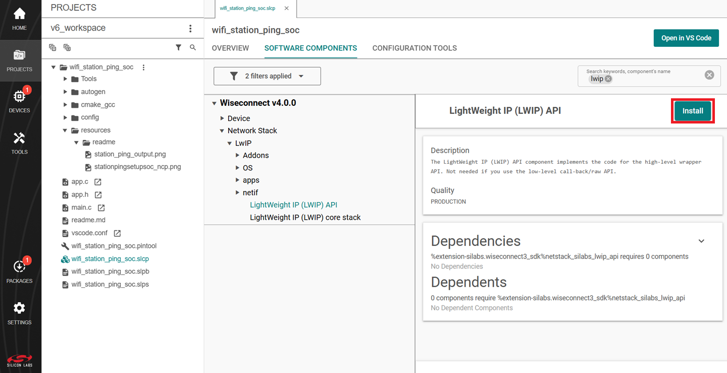
Note: Image is for illustration only. Component details shown may be outdated.
Studio will add the component and display a success message.
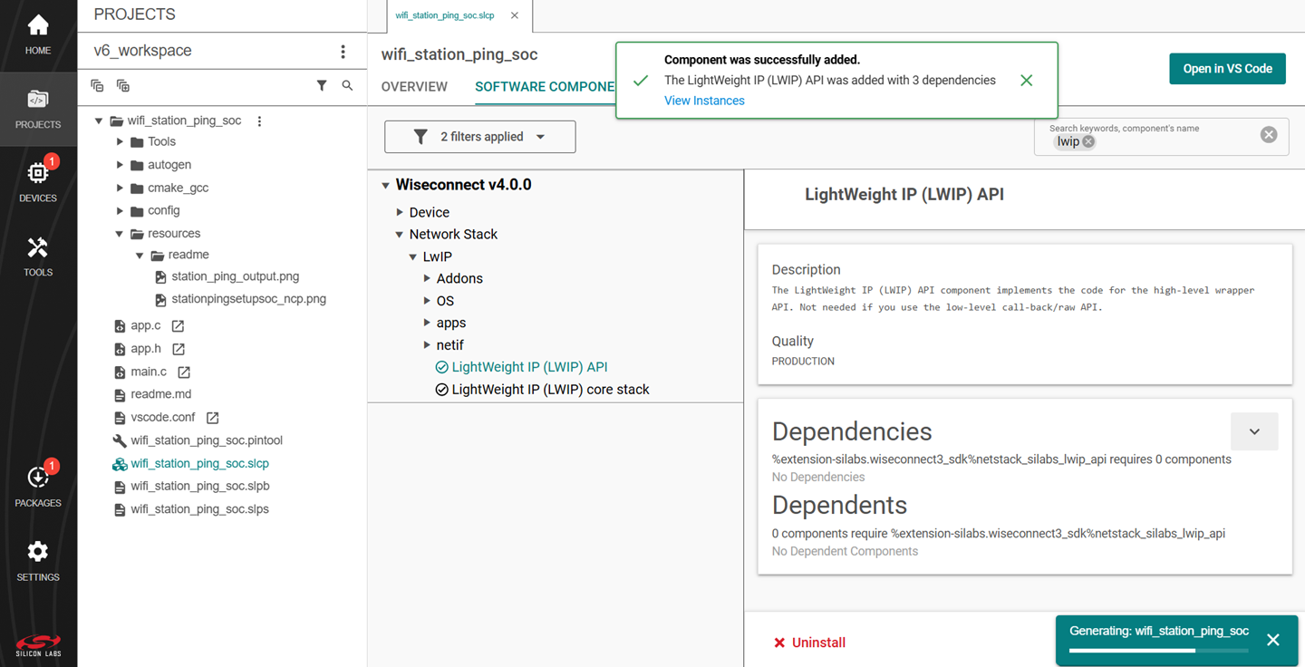
Note: Image is for illustration only. Component details shown may be outdated.
You may use the Component Editor to configure a component after adding it or to configure other components in your example.
Remove a Component#
View the list of WiSeConnect extension components by following steps 1-3 of the previous section.
Select the Installed filter to view the components you have installed.
Browse or search for and select the component you want to remove.
Select the component and click Uninstall.
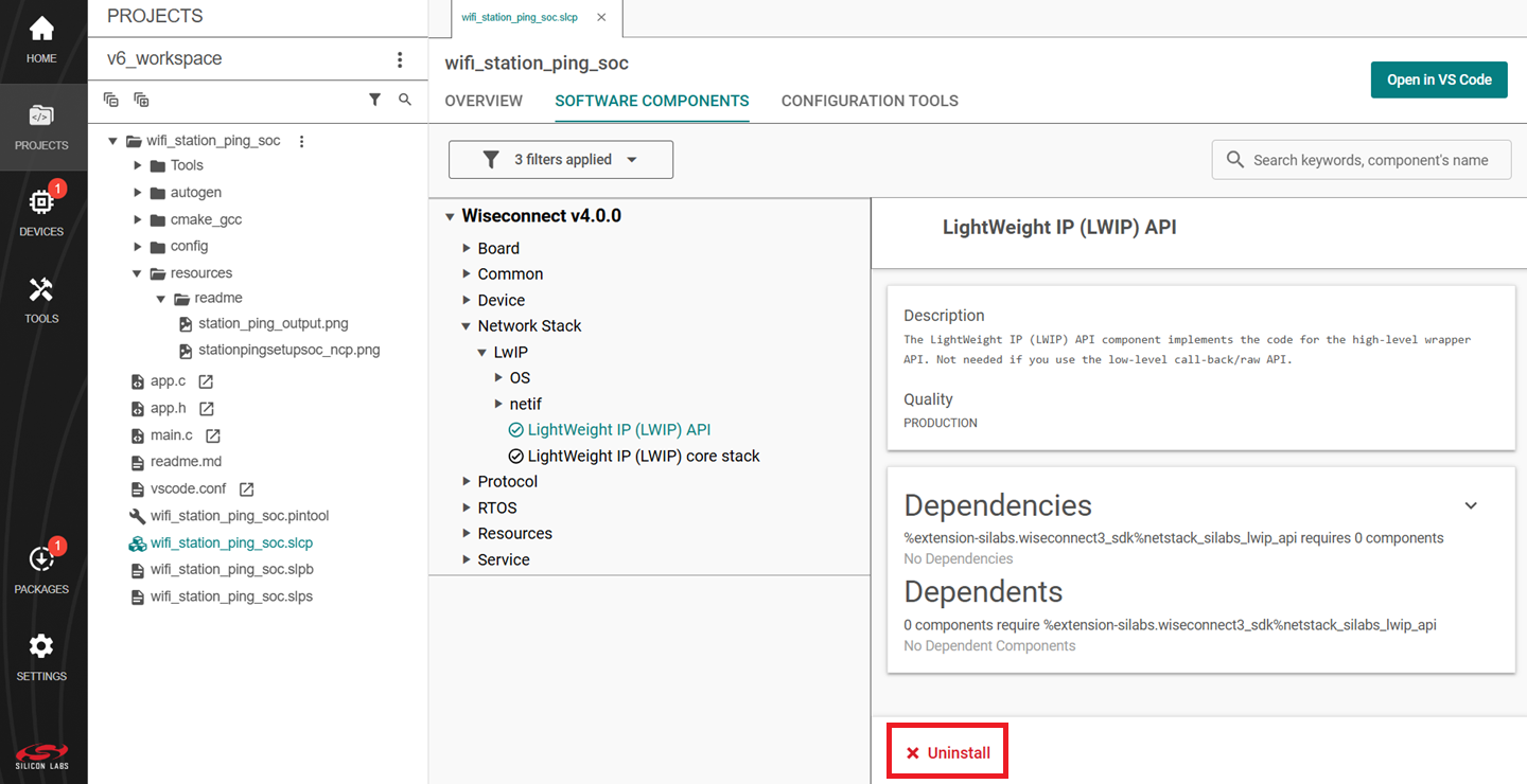
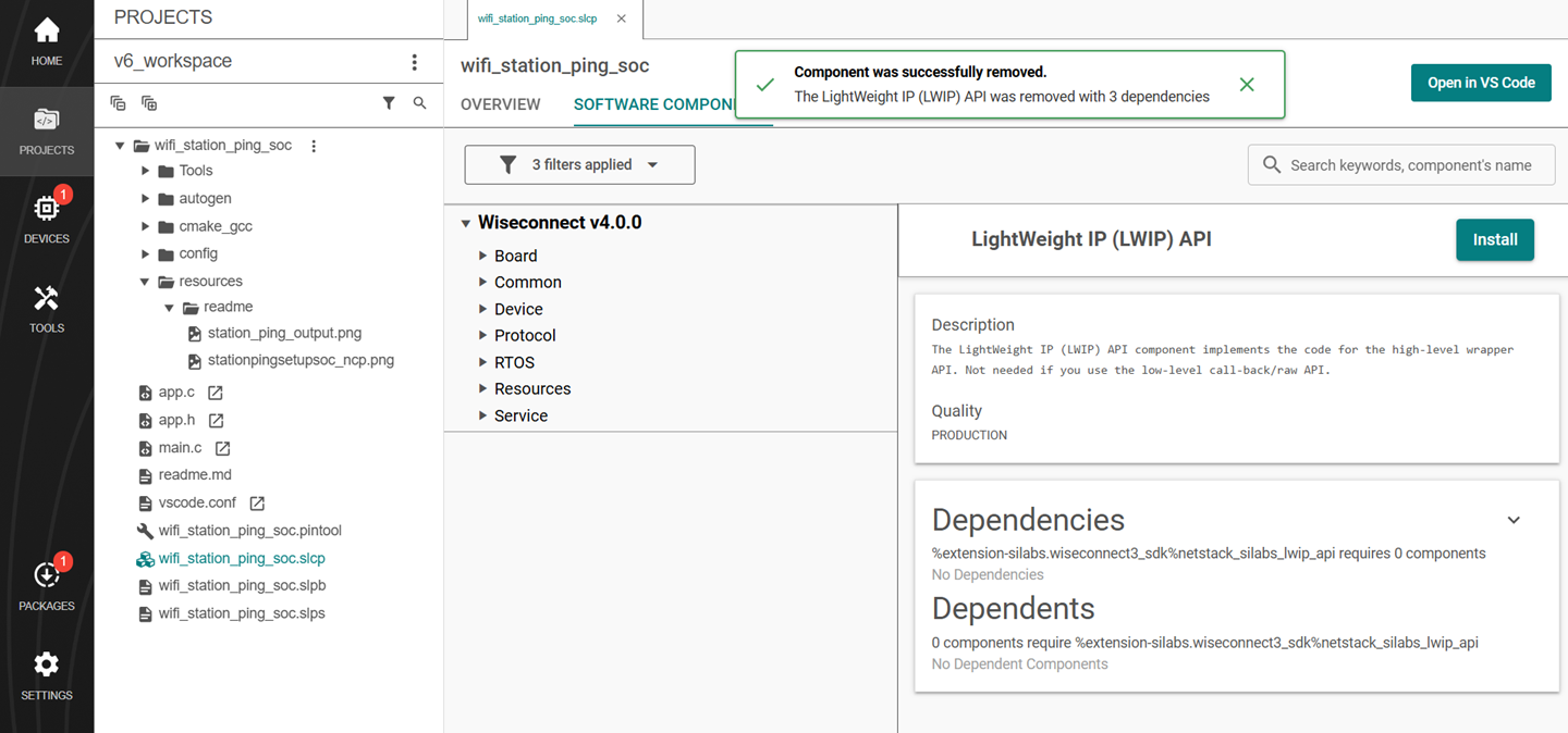
Note: Image is for illustration only. Component details shown may be outdated.
Measure Power Usage#
The following are the steps for measuring the power usage of an SiWx91x board.
Connect Hardware for Power Measurement#
If you are using a radio board, the connection is as described in the Connect SiWx91x to Computer section.
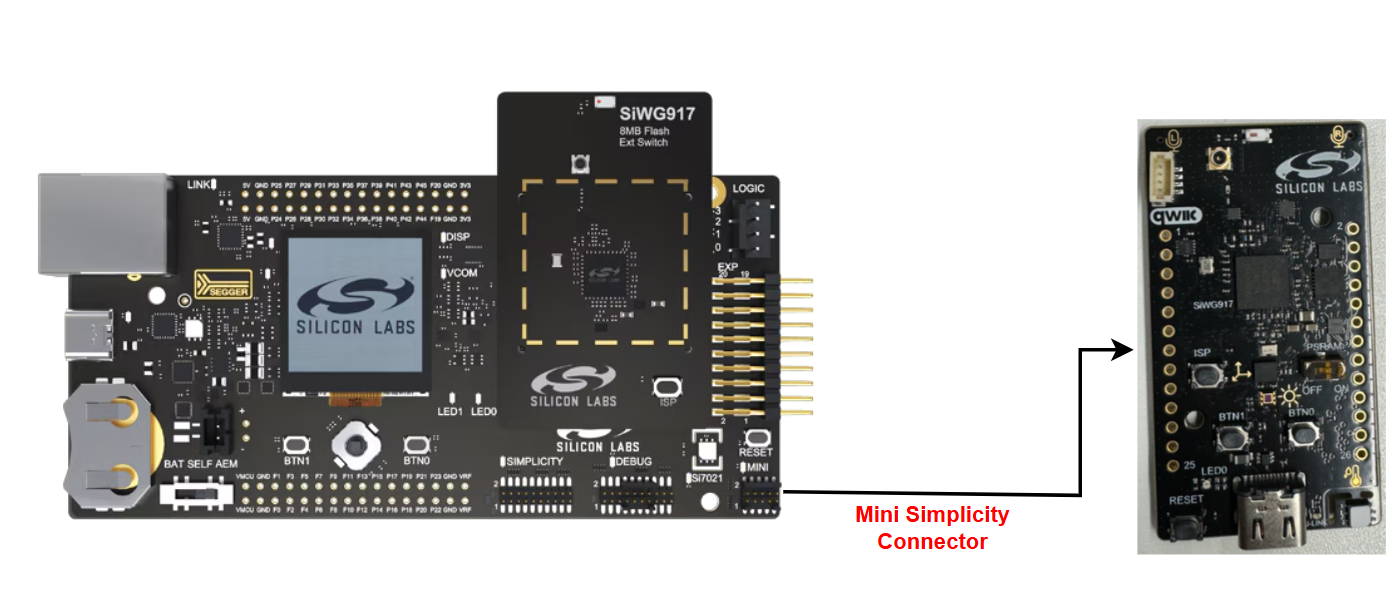
If you are using an explorer kit board or dev kit board, you need to connect it to a WPK board for power measurement. Follow the steps below:
Flash the desired application to the BRD2605A.
Ensure the WPK + BRD4338A is not connected to BRD2605A.
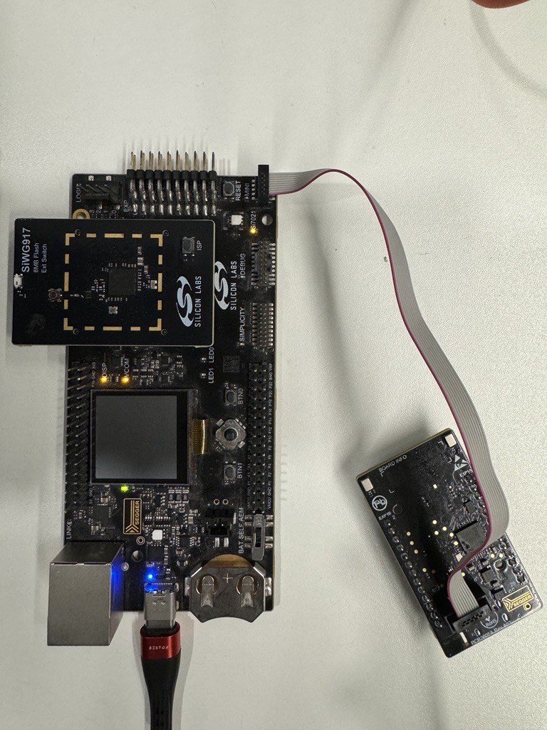
Connect the BRD2605A with WPK + BRD4338A via the Mini Simplicity Connector.
Make sure you remove the USB cable from BRD2605A.
Connect the PC with BRD4338A + WPK to the PC via the USB-C type cable as shown below.
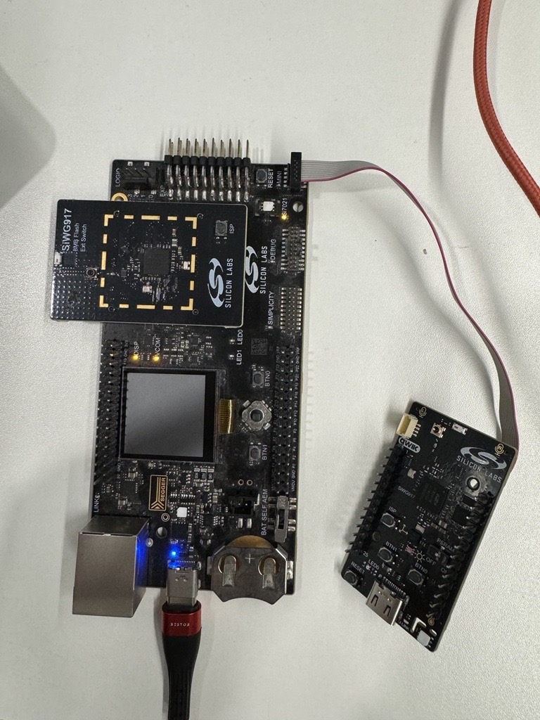
To view outputs of the application, you can connect the BRD2605A to the PC with the USB-C type cable (sometimes this is not working and it affects the current consumption).
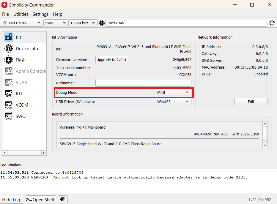
Check in the Simplicity Commander if the Debug Mode is selected as MINI.
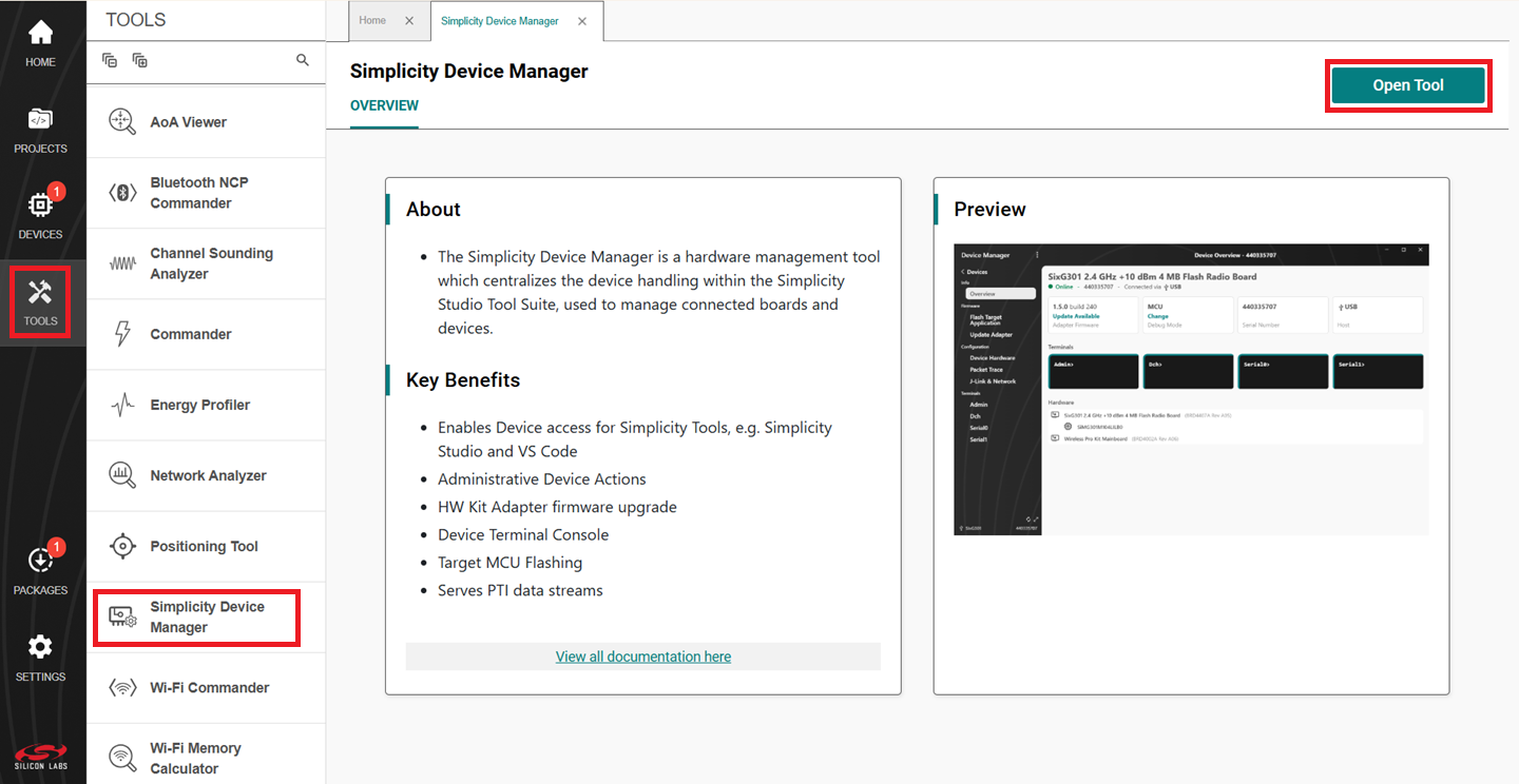
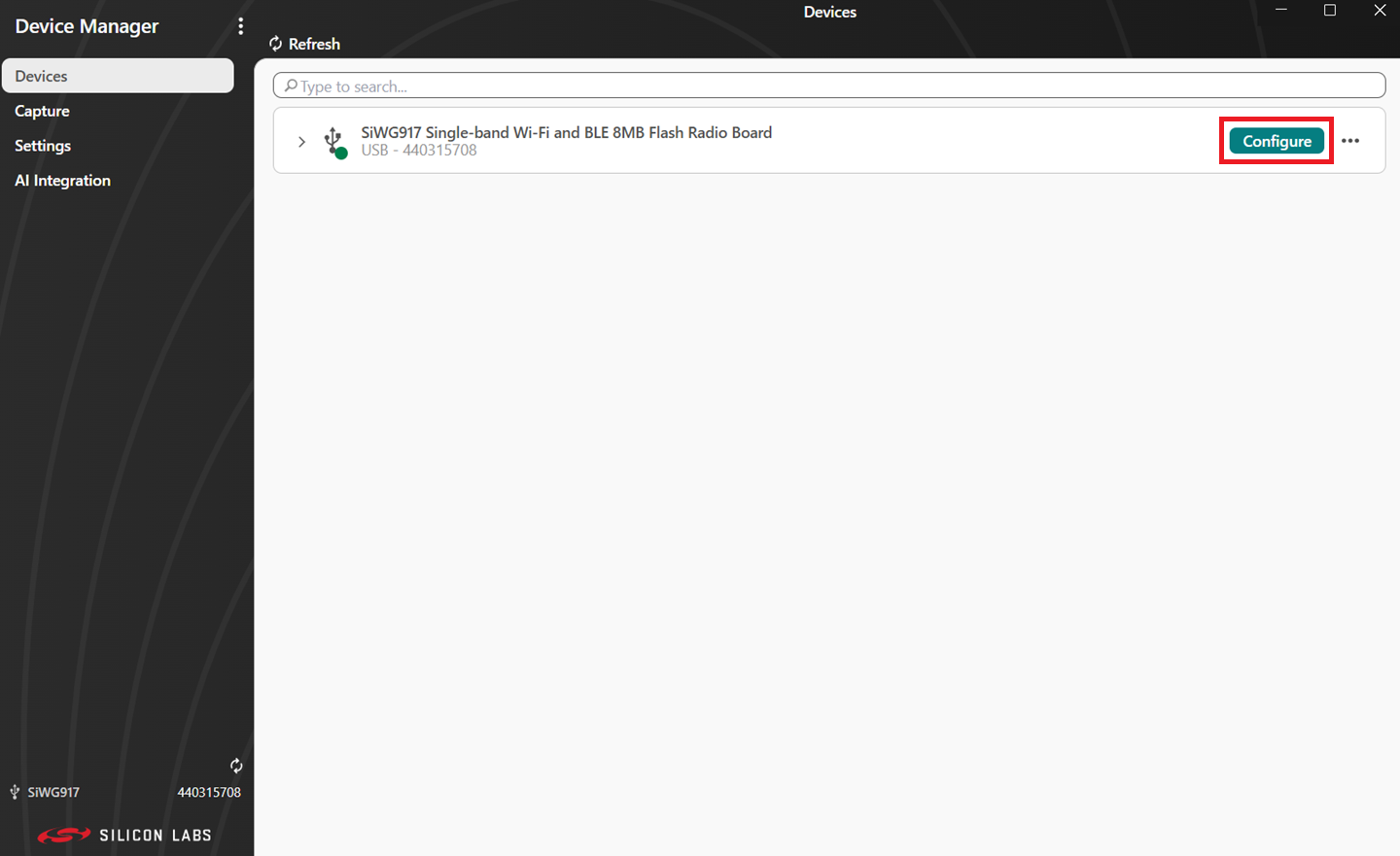
In Simplicity Studio, Go to TOOLS → Simplicity Device Manager → Click on Open Tool.
Click on Configure.
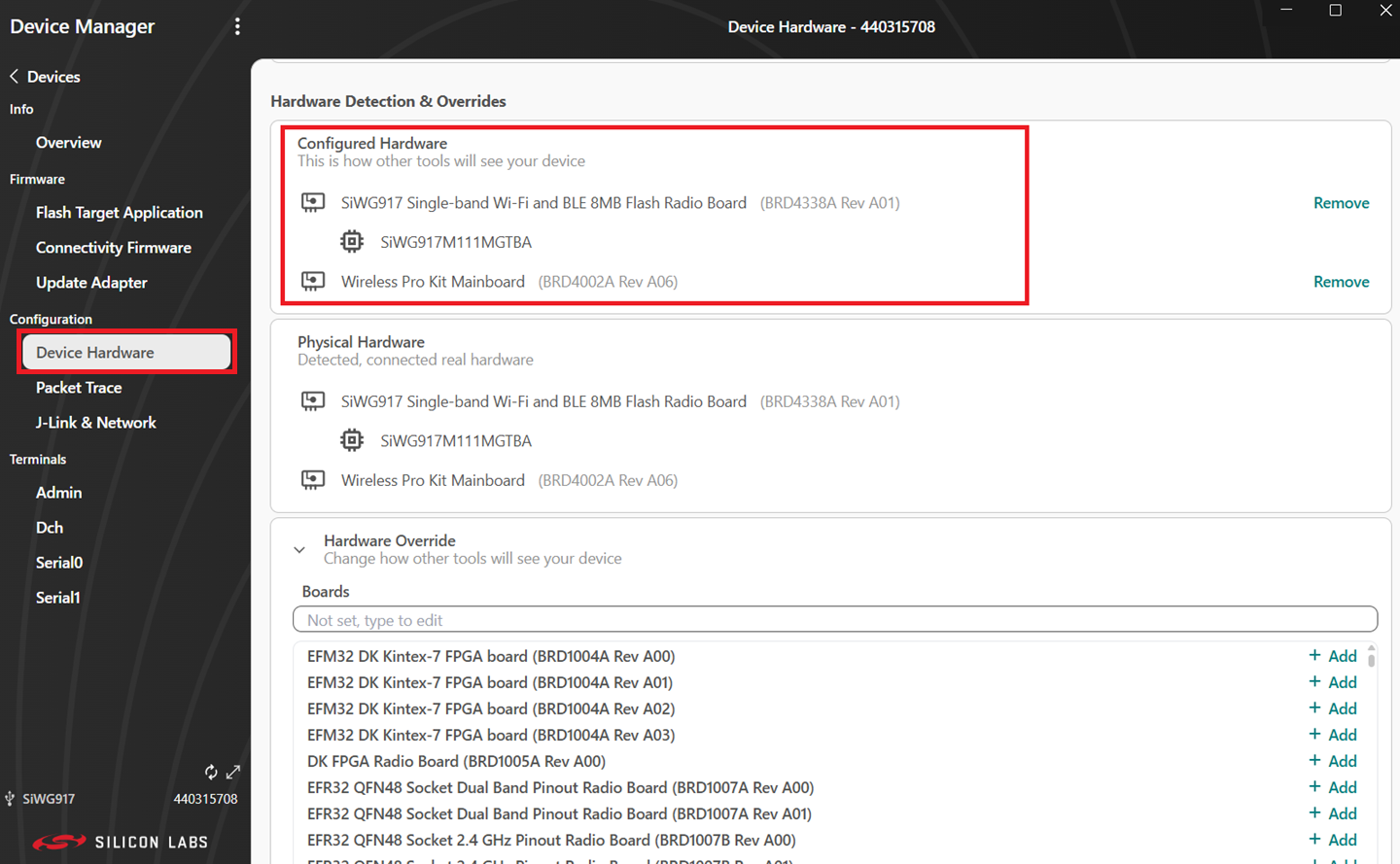
Navigate to Device Hardware and make sure you have the following configurations.
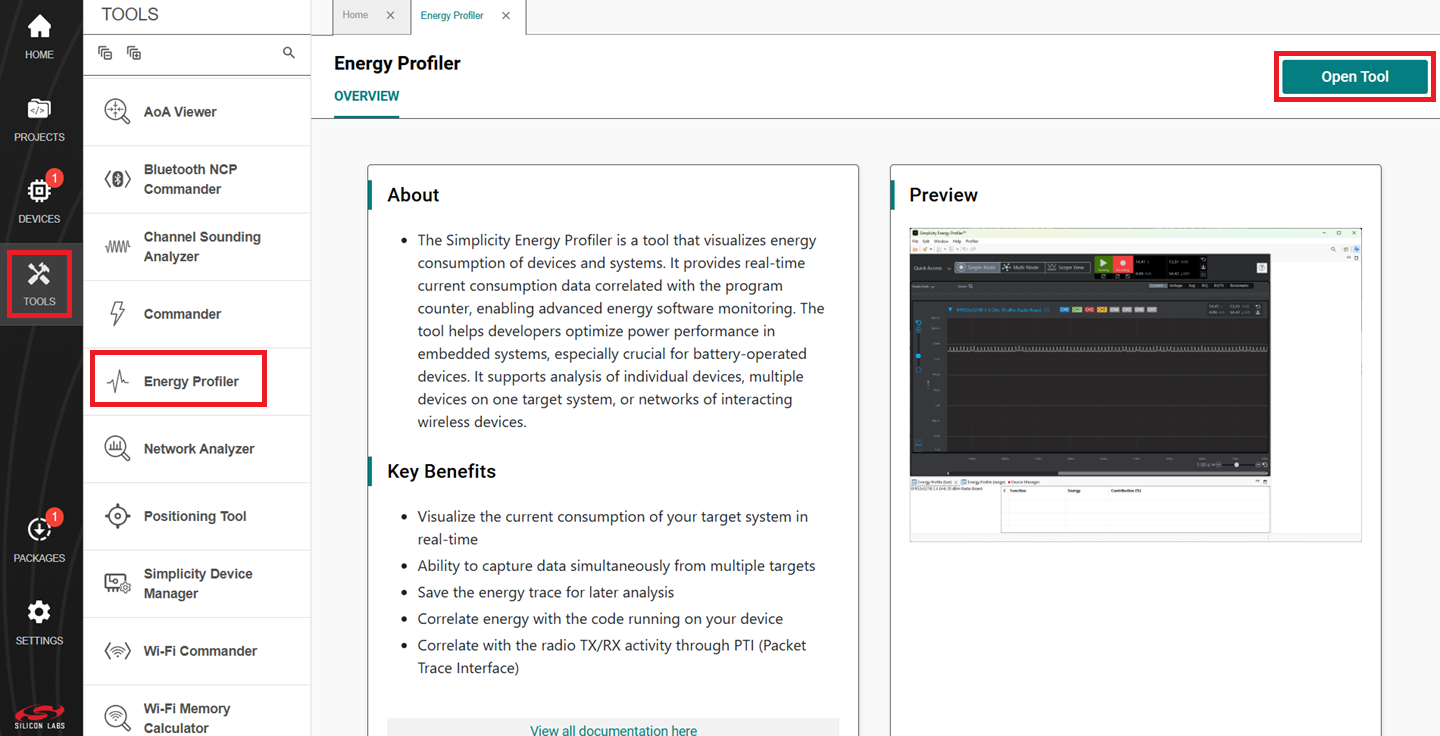
Navigate to TOOLS -> Energy Profiler → Open Tool
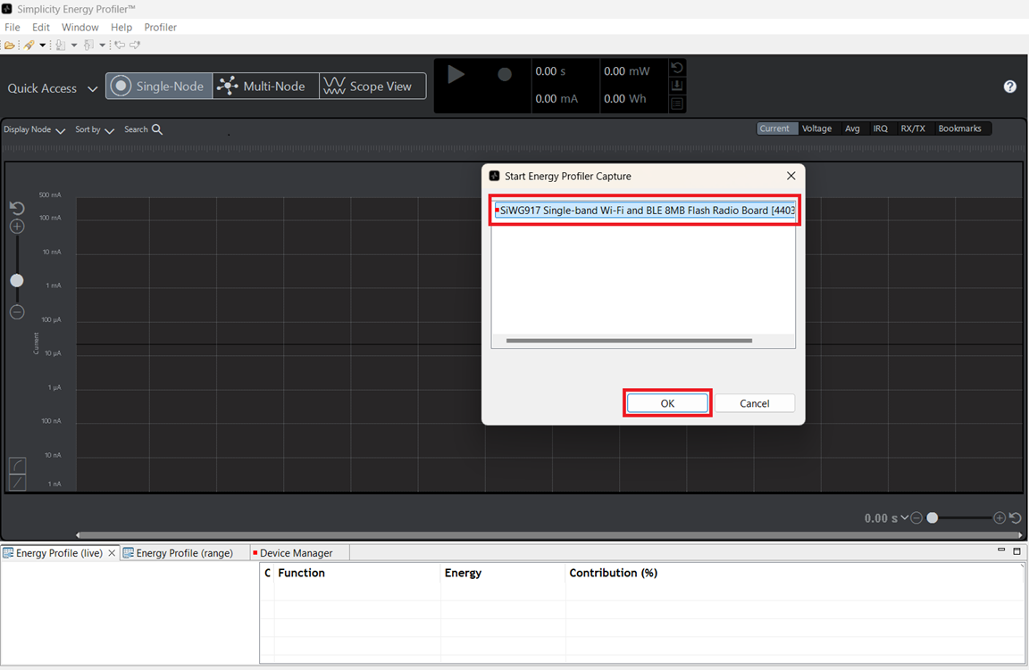
Click on Quick Access -> Start Energy Capture
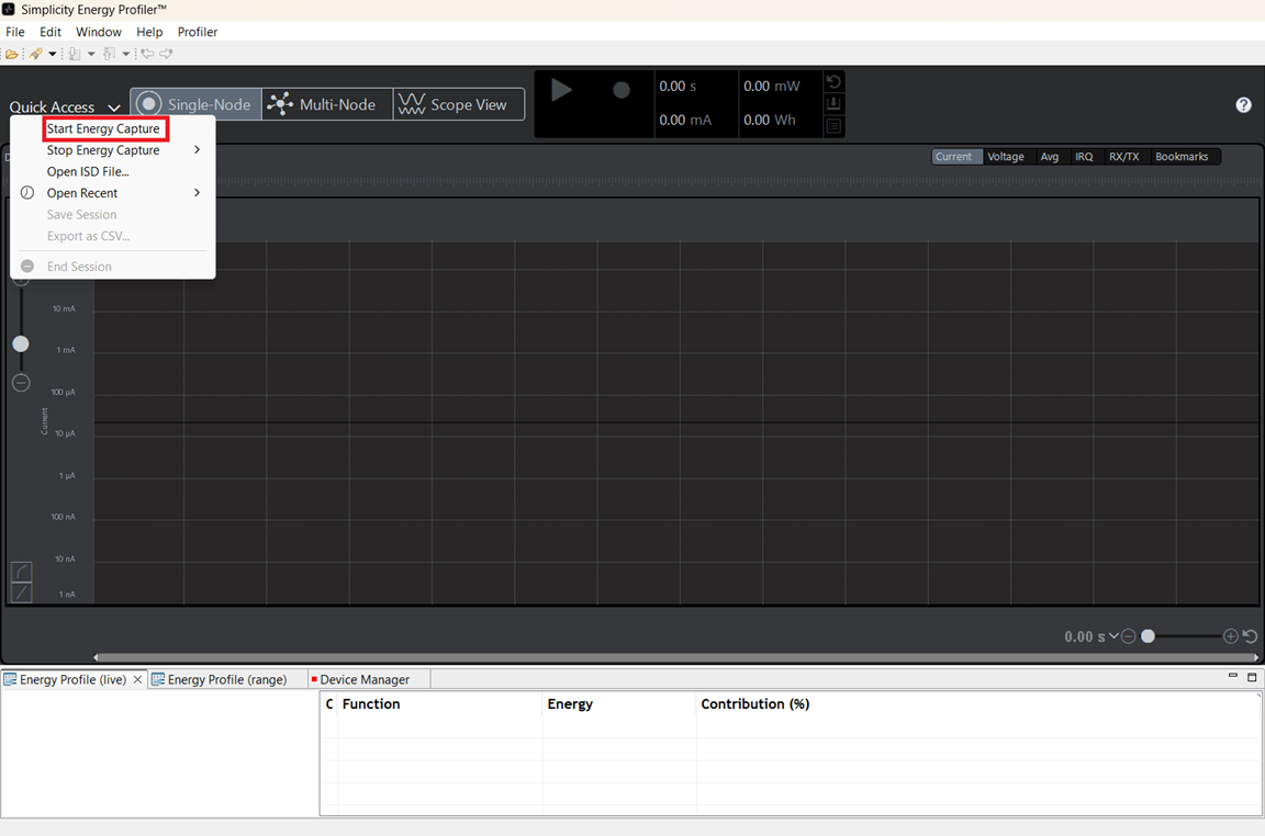
Select the Hardware from the drop down menu and click OK.
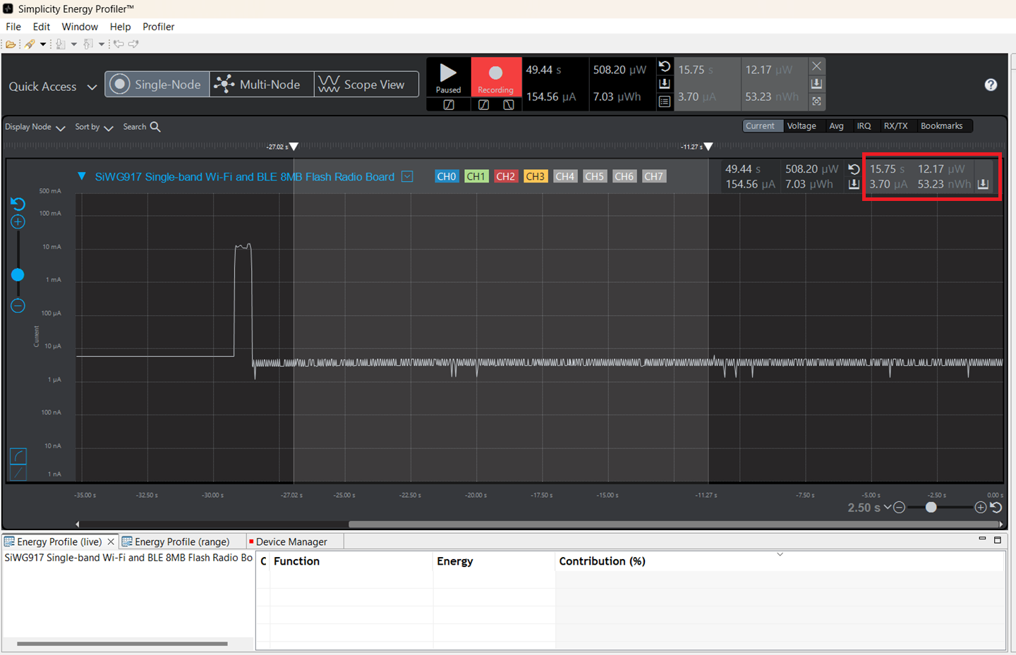
Measure Power using Energy Profiler#
See the From the Energy Profiler section for steps to measure power using the Simplicity Studio Energy Profiler.