Creating a Wi-SUN Network#
In these instructions, you will compile and load a simple Wi-SUN Ping application on a node and a Wi-SUN Border Router demo image on another node. The Creating a Network section describes how to use the examples to create a network. The Network Analyzer section on the Going Further page describes how to use Network Analyzer to observe traffic across the network.
When working with an example application in Simplicity Studio, you will be executing the steps in the following order:
Create a project based on an example.
Configure the project.
Build the application image and flash it to your device.
These steps are described in detail in the following sections. These procedures are illustrated for a mainboard with an EFR32MG12. Note: Your SDK version may be later than the version shown in the figures.
You should have your mainboard connected.
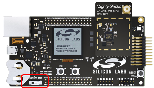
For best performance in Simplicity Studio 5, be sure that the power switch on your mainboard is in the Advanced Energy Monitoring or AEM position, as shown in the following figure.
Flashing the Wi-SUN Border Router#
Every Wi-SUN example requires a Wi-SUN Border Router to create and manage a Wi-SUN network for the Wi-SUN devices to join. It provides an easy and quick medium to evaluate the Silicon Labs Wi-SUN stack solution without deploying an expensive and cumbersome production-grade Wi-SUN Border Router. A CLI (Command-Line Interface) is exposed to facilitate the configuration.
Note: Make sure your mainboard has the latest “Adapter FW” to avoid any issue when using the example CLI. To do so:
In the Launcher perspective, click the radio board listed in the Debug Adapters view.
In the OVERVIEW tab, verify the Adapter FW version in the General Information card.
If Simplicity Studio 5 proposes to update the firmware, do so.
The Wi-SUN SoC Border Router demonstration is delivered in a binary format for an out-of-the-box experience. The implementation scales for a production-grade SoC Border Router maintaining several hundreds of Wi-SUN nodes. For a production-grade Linux border router solution, refer to the Wi-SUN Linux Border Router section to get started.
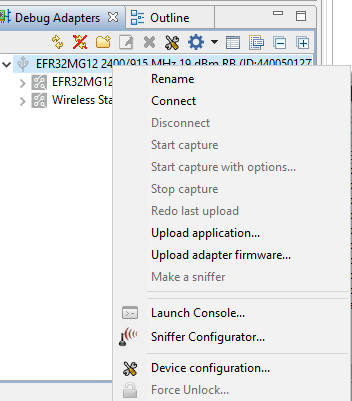
In the Debug Adapters view, select the device that will be the Wi-SUN border router. Note: To rename the device so that you know which device is the Border Router, right-click it and select Rename on the context menu.
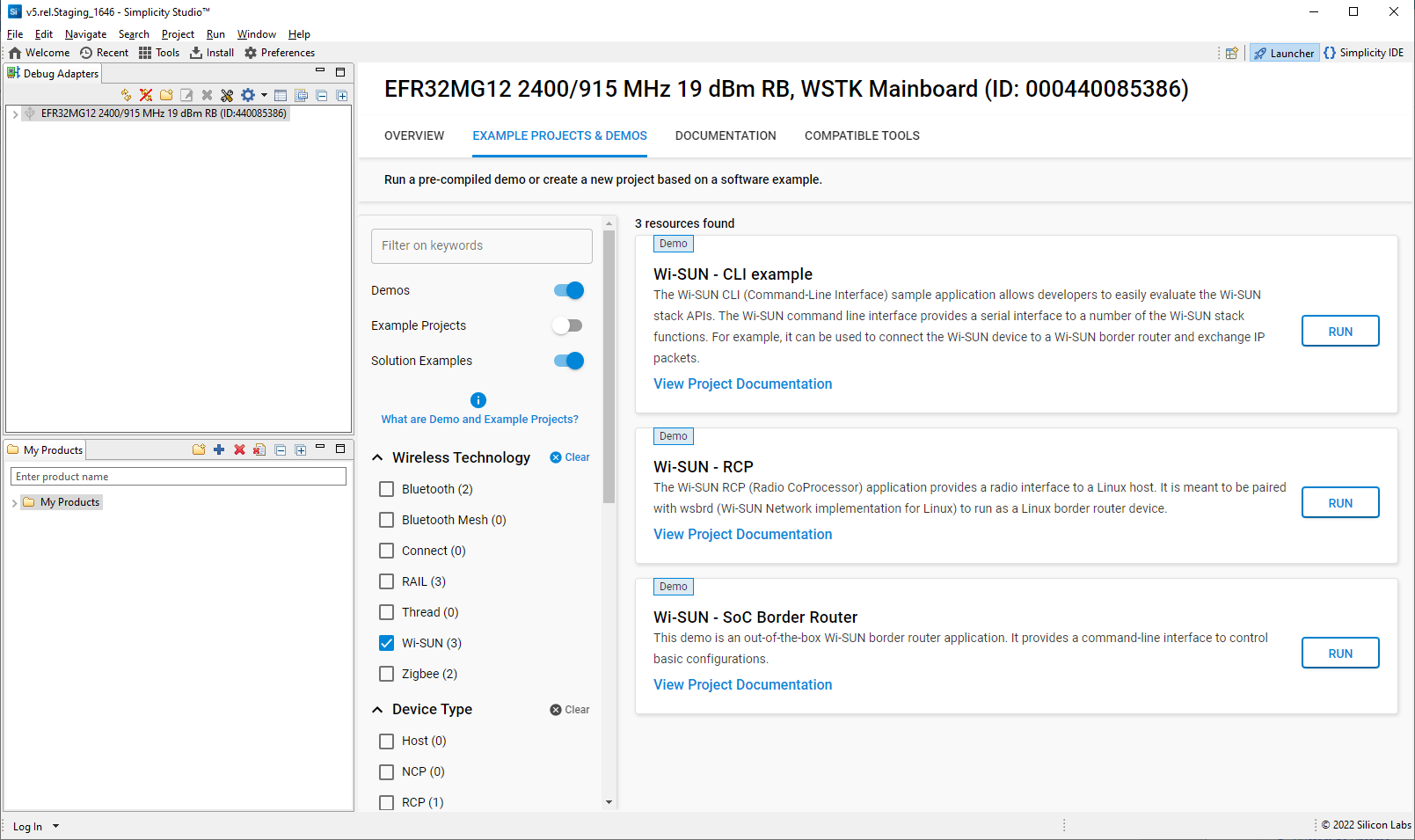
Navigate to the EXAMPLE PROJECTS & DEMOS tab and turn off the Example Projects filter. Click RUN next to Wi-SUN – SoC Border Router demo.
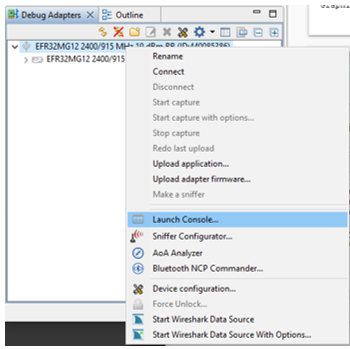
Start the Wi-SUN Border Router with the CLI interface. In the Debug Adapters view, right-click the Border Router device and click Launch Console, as shown. Alternatively, click Tools in the Simplicity IDE menu and select 'Device Console'.
To get a prompt on the Console, go to the Serial 1 tab and press Enter. To start the Wi-SUN Border Router with default FAN 1.1 PHY, enter:
> wisun start_fan11Or with default FAN 1.0 PHY using the following command:
> wisun start_fan10
Creating a Project Based on an Example#
Simplicity Studio 5 (SSv5) offers a variety of ways to begin a project using an example application. The online Simplicity Studio 5 User’s Guide describes them all. This guide uses the File > New > Silicon Labs Project Wizard method because it takes you through all three of the Project Creation Dialogs. Details on each creation dialog option may be found in the Simplicity Studio 5 User’s Guide.
In the Debug Adapters view, select the target part for the application node. This should be a different part than the one used for the border router in the previous section.
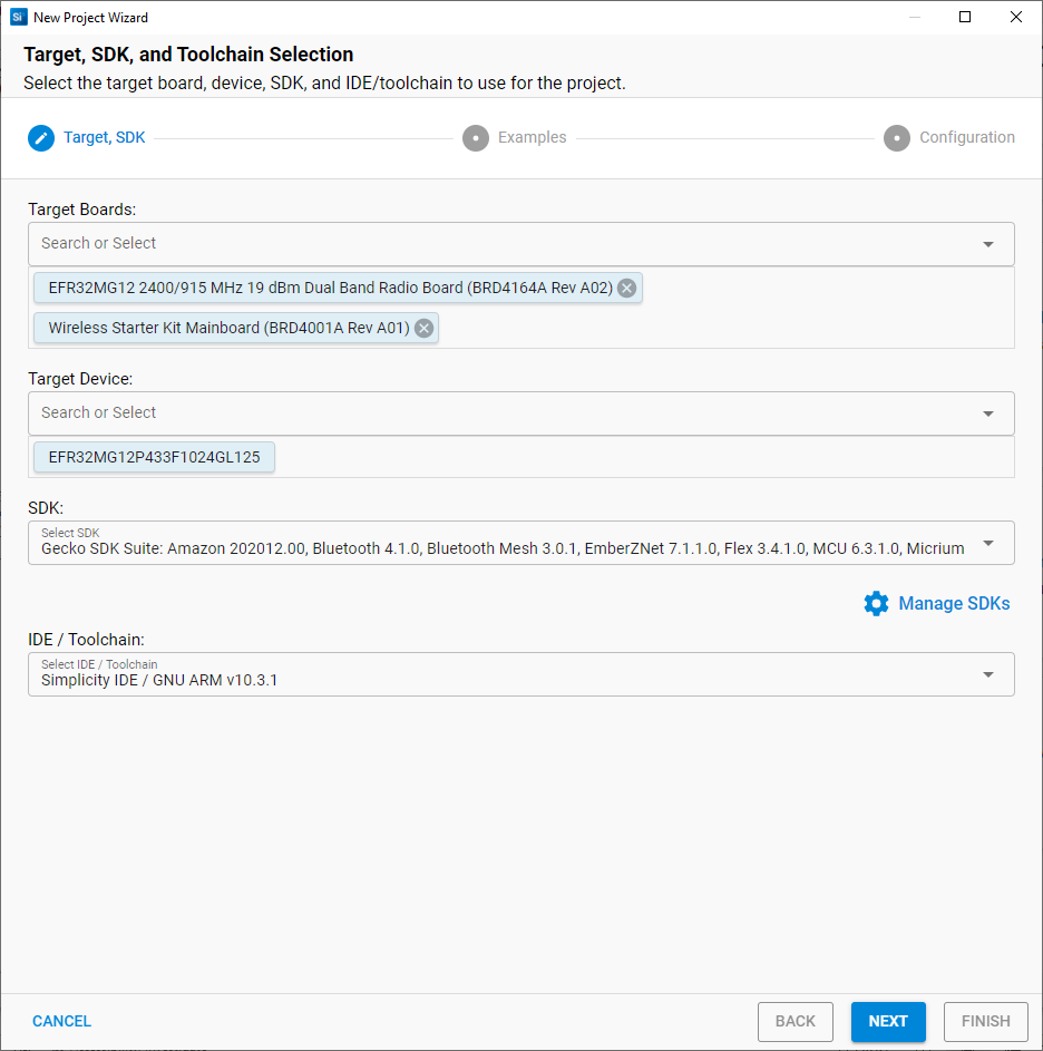
Open SSv5’s File menu and select New > Silicon Labs Project Wizard. The Target, SDK, and Toolchain Selection dialog opens. Do not change the default Simplicity IDE / GNU ARM v<version> toolchain supported by Wi-SUN. Click NEXT.
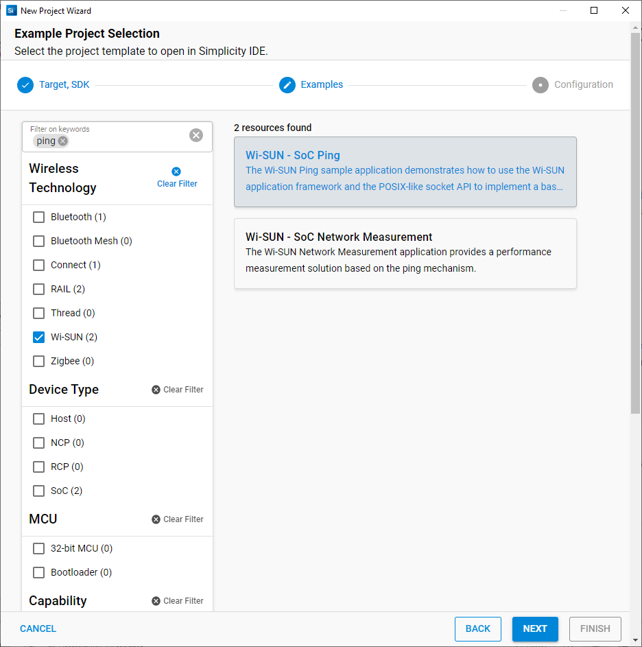
The Example Project Selection dialog opens. Use the ‘Wi-SUN’ Technology Type and Keyword filters to search for a specific example, in this case Wi-SUN – SoC Ping. Select it and click NEXT.
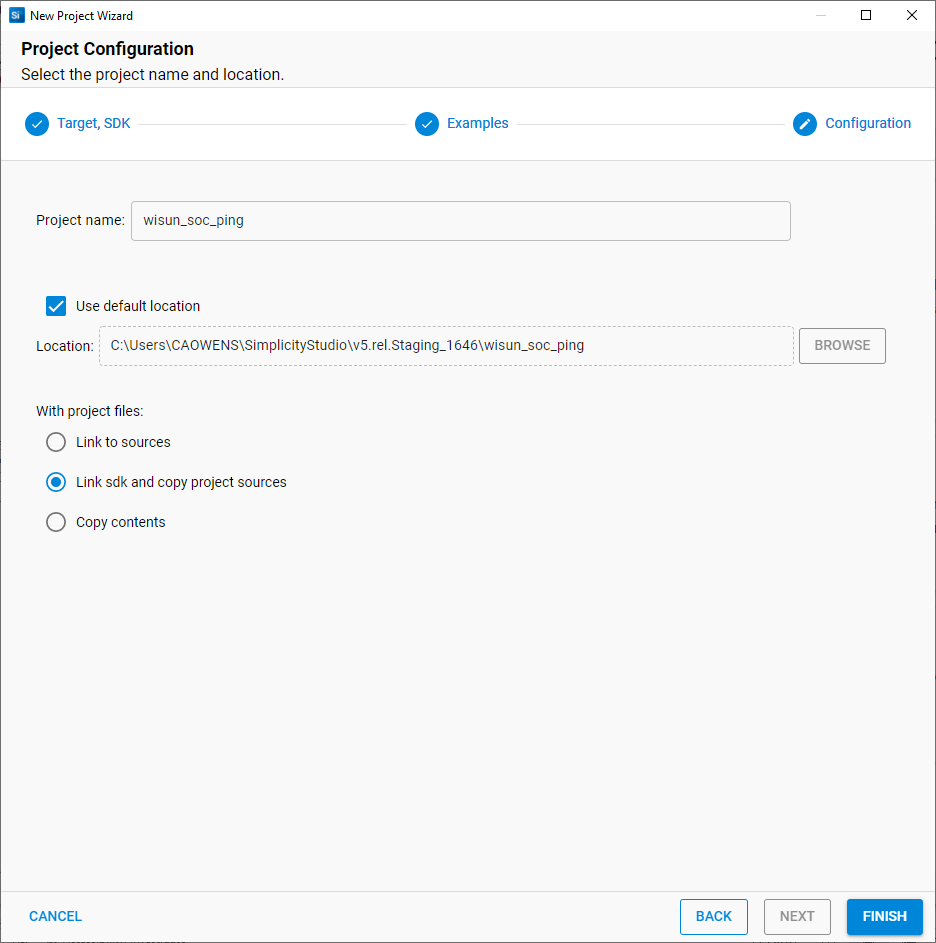
The Project Configuration dialog opens. Here you can rename your project, change the default project file location, and determine if you will link to or copy project files. Note that if you change any linked resource, it is changed for any other project that references it. Click FINISH.
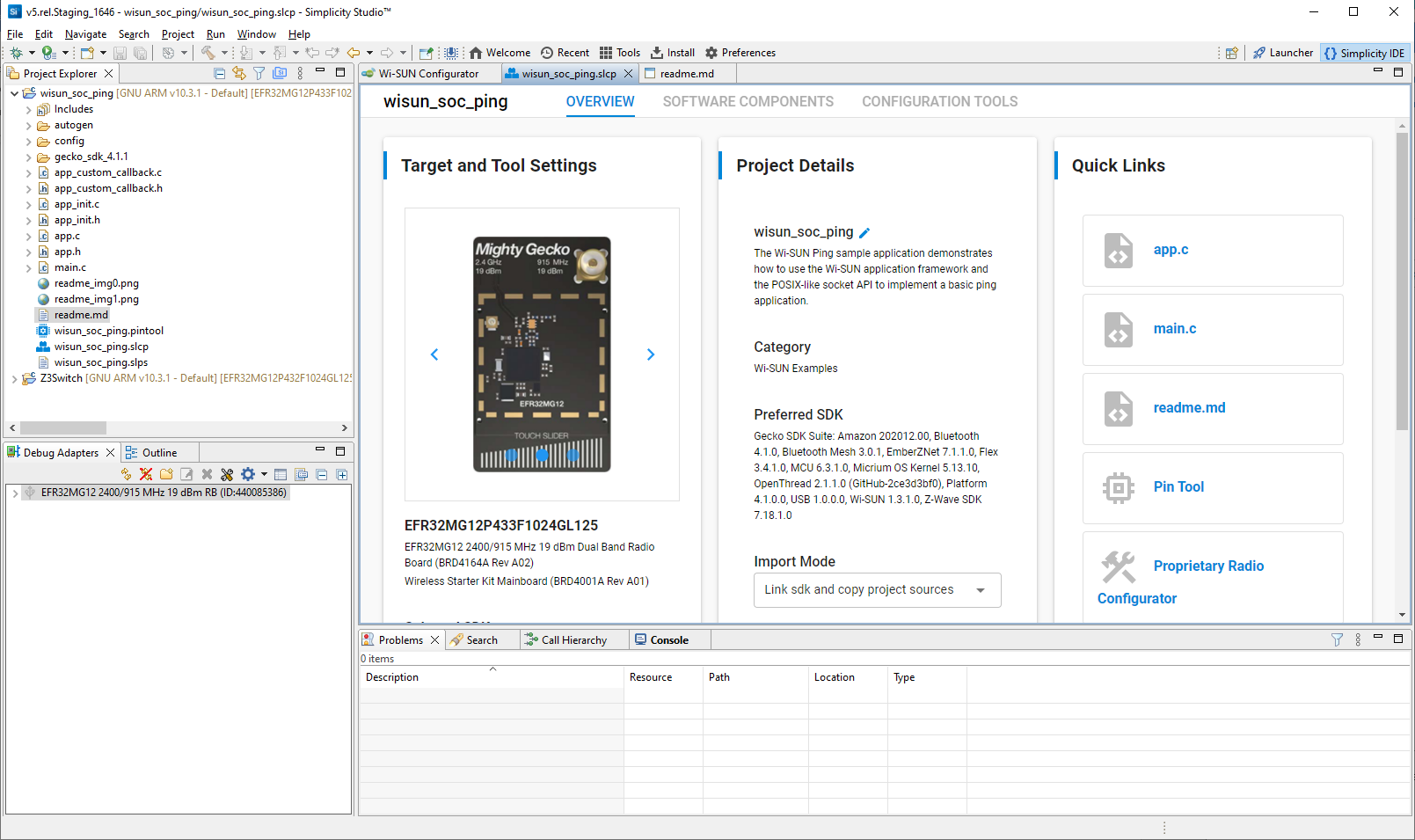
The Simplicity IDE Perspective opens with the project documentation (readme.md). Click the <project>.slcp tab to see the Project Configurator OVERVIEW tab. See the online Simplicity Studio 5 User’s Guide for details about the functionality available through the Simplicity IDE perspective and the Project Configurator.
Configuring the Project#
Silicon Labs Wi-SUN applications are built on a Gecko Platform component structure. Click the SOFTWARE COMPONENTS tab to see a complete list of component categories.
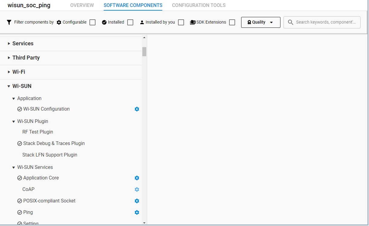
The project is configured by installing and uninstalling components and configuring installed components. Installed components are shown with a circled checkmark on their left. Click Installed Components to see a filtered list of components installed by the example application.
Configurable components have a gear symbol on their right. Select a component to see information about it.
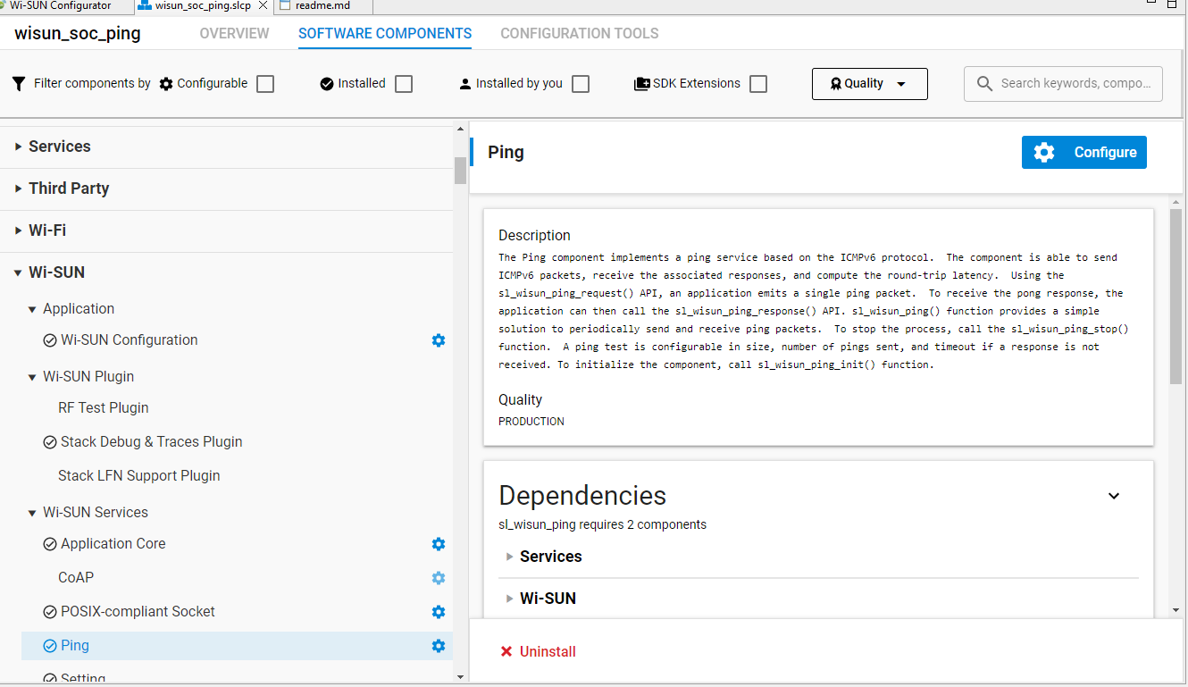
If the component is configurable, click CONFIGURE to open the Component Editor in a new tab.
For example, in the Ping component you can configure various parameters that change the way the wisun-ping application behaves.
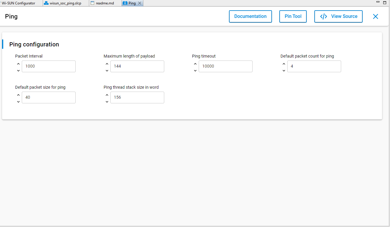
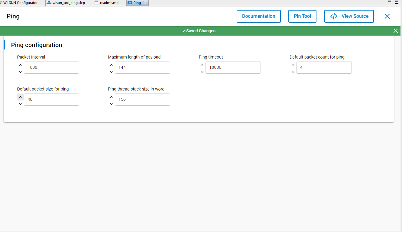
Any changes you make are autosaved, and project files are autogenerated.
In addition to the Project Configurator tab (<project>.slcp), a Wi-SUN Configurator tab is also available. For more information about using the Wi-SUN Configurator and how to change the default Wi-SUN PHY, see UG495: Silicon Labs Wi-SUN Developer’s Guide.
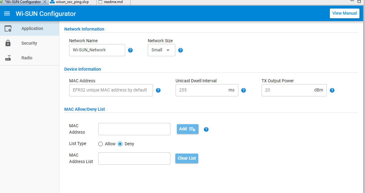
If you make changes, the Wi-SUN Configurator tab has an asterisk to the left. Save changes (CTRL-S) when you are finished updating Wi-SUN Configurator settings. If you build the project without saving changes, the changes are saved automatically.
Building the Project#
You can either compile and flash the application automatically, or manually compile it and then flash it.
Automatically Compile and Flash#
You can automatically compile and flash the application to your connected development hardware in the Simplicity IDE, and open a Debug interface. Click Debug

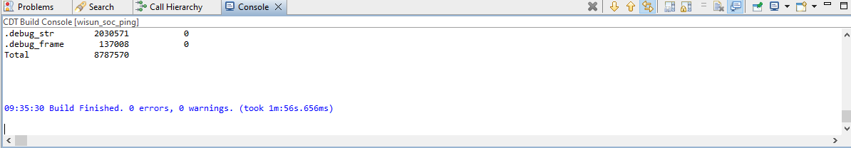
Progress is displayed in the console and a progress bar in the lower right.
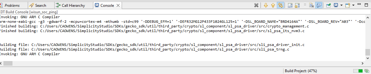
The project should build without error.
When building and flashing are complete a Debug perspective is displayed. Click Resume (

Next to the Resume control are Suspend, Terminate, Disconnect, and stepping controls. Click Disconnect (
Manually Compile and Flash#
After you generate your project files, instead of clicking Debug, click Build (

You can load the binary image through Project Explorer view.
Locate the <project>.bin, .hex, or .s37 file in the Binaries subdirectory.
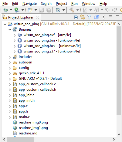
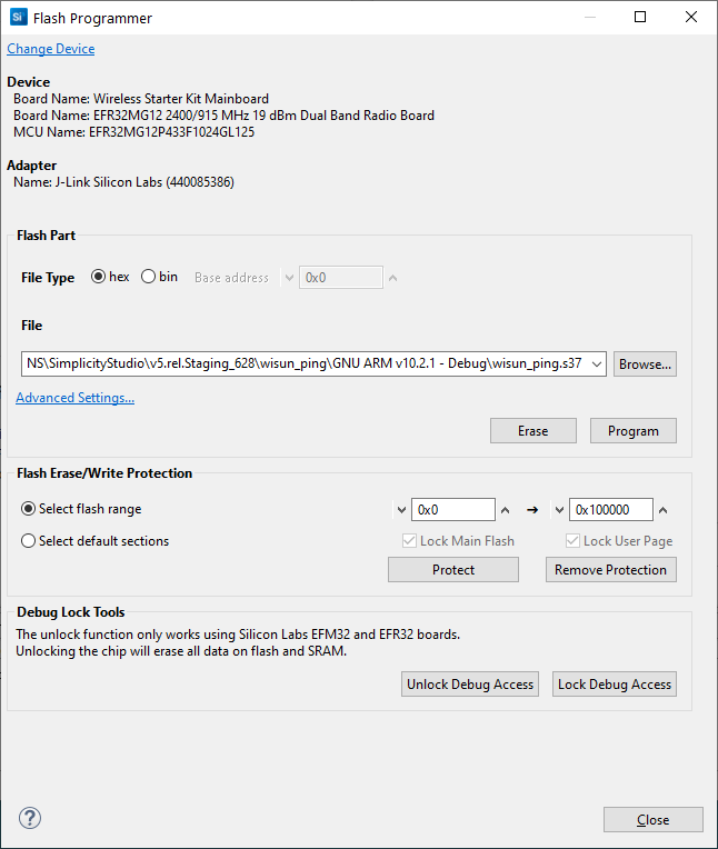
Right-click the file and select Flash to Device... If you have more than one device connected, select a device to program. The Flash Programmer opens with the file path populated. Click PROGRAM to flash the image to the device.
Flashing a Bootloader#
All Silicon Labs examples require that a bootloader be installed. A bootloader is a program stored in reserved flash memory that can initialize a device, update firmware images, and possibly perform some integrity checks. Silicon Labs networking devices use bootloaders that perform firmware updates in two different modes: standalone (also called standalone bootloaders) and application (also called application bootloaders). An application bootloader performs a firmware image update by reprogramming the flash with an update image stored in internal or external memory. By default, a new device is factory-programmed with a bootloader, which remains installed until you erase the device. The Gecko Bootloader is a code library configurable through Simplicity Studio’s IDE to generate bootloaders that can be used with a variety of Silicon Labs protocol stacks. The Gecko Bootloader is used with all EFR32xG parts. For more information about bootloaders see Bootloader Fundamentals.
By default, a new device is factory-programmed with a bootloader. If you have a new device, haven’t cleared the bootloader region for your part or have a supported bootloader image already flashed on your device, skip this step and continue with the next section.
With Silicon Labs Wi-SUN, the bootloader serves to start the application code within the image you created and flashed in the previous procedure. Once you have installed a bootloader image, it remains installed until you erase the device.
To flash a bootloader, first select one of the bootloader examples, such as SPI Flash Storage Bootloader (single image), and build and flash it as described above. For more information see UG489: Silicon Labs Gecko Bootloader User’s Guide for GSDK 4.0 and Higher or Silicon Labs Gecko Bootloader User’s Guide for Series 3 and Higher.
If you are working with the Gecko Bootloader, bootloader images must be formatted as GBL files. To create a GBL file from an .s37 or binary, follow the instructions in the GBL File Creation section of the Simplicity Commander Reference Guide. The exact format of the GBL file depends on the hardware you selected.
Creating a Network#
Depending on the example application, you may be able to interact with it through your development environment’s Console interface using a CLI (command-line interface). The console interface allows you to form a network and send data using the border router device created in section Flashing the Wi-SUN Border Router and the application node.
To launch the Console interface, in the Simplicity IDE perspective right-click the application node in the Debug Adapters View. Select Launch Console. Alternatively, click Tools in the Simplicity IDE menu and select Device Console.
To get a prompt on the Console, go to the Serial 1 tab and press Enter.
Connect the Wi-SUN Ping WSTK#
The Wi-SUN Ping application automatically starts by connecting to the Border Router. If the connection is successful, the application should output the traces below in the console.
[Connecting to "Wi-SUN Network"]
> [Join state: Authenticate (2)]
[Join state: Acquire PAN Config (3)]
[Join state: Configure Routing (4)]
[Join state: Operational (5)]
Addresses:
[GLOBAL : fd00:7283:7e00:0:5e02:72ff:fe96:ca9c]
[LINK_LOCAL : fe80::5e02:72ff:fe96:ca9c]
[BORDER_ROUTER : fd00:6172:6d00:0:b6e3:f9ff:fea6:3aa]
[170 s]The following is an illustration of connecting the Wi-SUN SoC Border Router application to the Wi-SUN SoC Ping Example Application. This setup allows showing the Border Router and the device consoles side by side, where Wi-SUN settings can be compared. If these do not match, the connection will fail. When using a Linux Border Router, use 'wsbrd_cli status' to check the Border Router settings.
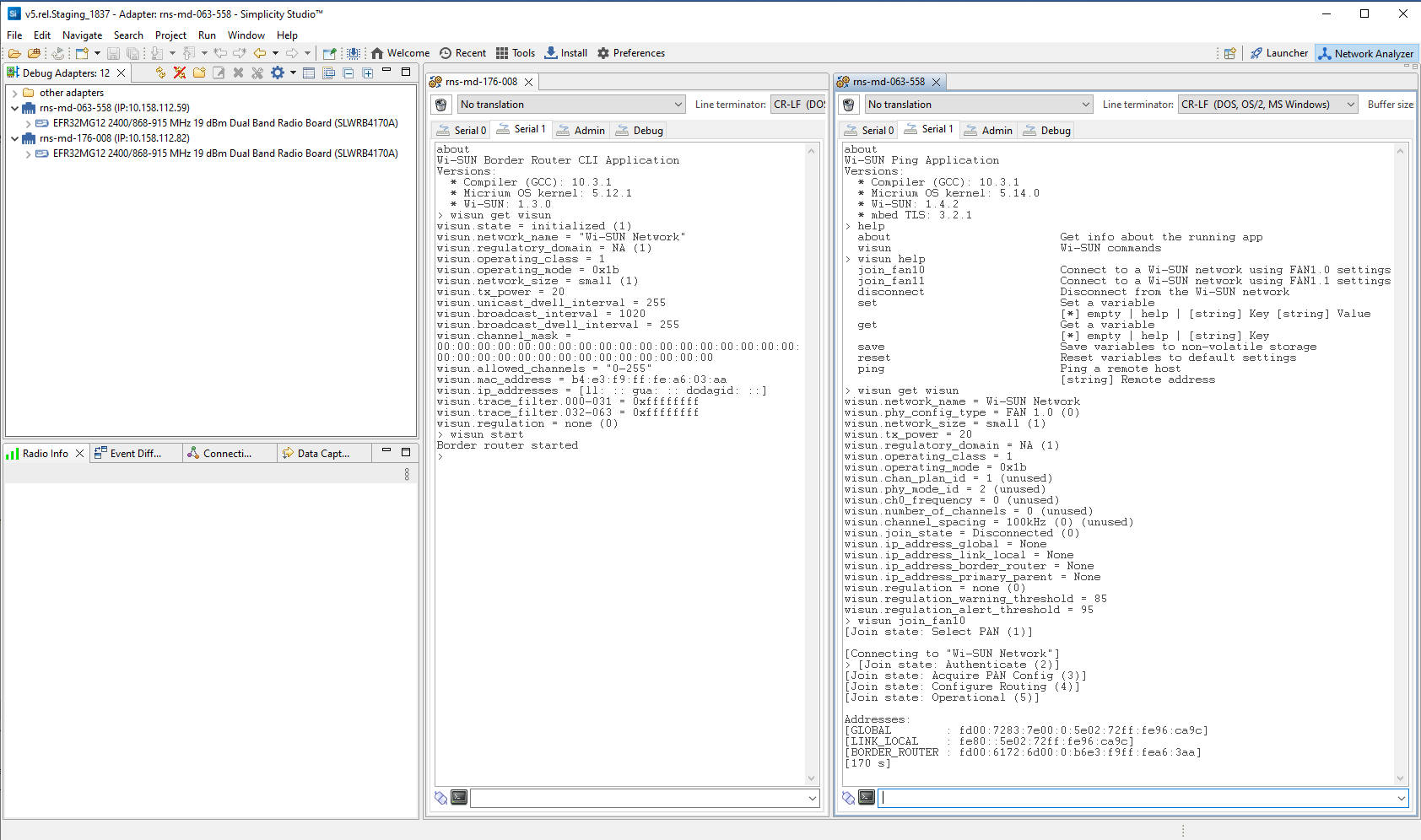
The two Wi-SUN devices (Border Router and Wi-SUN SoC Ping) are now part of the same Wi-SUN network.
Ping the Wi-SUN Border Router#
To check the commands exposed in the Wi-SUN Ping application, enter:
wisun help
To retrieve the Border Router IPv6 address, enter:
wisun get wisun.ip_address_border_router
The Wi-SUN Ping application has a specific command: wisun ping [IPv6 address]. Use the command to ping the Border Router.
wisun ping [Border Router Global IPv6 address]
If the ping command is successful, the pong message size and latency are output on the console.
> wisun ping fd00:6172:6d00:0:20d:6fff:fe20:bd95`
PING fd00:6172:6d00:0:20d:6fff:fe20:bd95: 40 data bytes
> [40 bytes from fd00:6172:6d00:0:20d:6fff:fe20:bd95: icmp_seq=1 time=196.231 ms]In this case, the ping took 196 milliseconds to come back to the Wi-SUN device. The ping command can be used to communicate with other Wi-SUN devices in the same Wi-SUN network.
Disconnect and Reconnect the Ping WSTK#
You need to disconnect the WSTK and reconnect it to apply new network settings, if you modified them on the Border Router (check these on the Linux Border Router using ‘wsbrd_cli status’).
Note: It may be worth going through this in situations where the Wi-SUN device does not connect to the Border Router.
To disconnect the WSTK, enter:
wisun disconnect
Check the Wi-SUN settings using:
`wisun get wisun````
Set the new Wi-SUN settings using:
wisun set wisun.<parameter> <value>
Use the online help or refer to the readme.md file (at the root of you project) to check what parameters are required for your FAN configuration, using:
wisun set wisun help
If you want to preserve your settings following a power cycle or reset, use:
wisun save
Depending on the FAN configuration, use one of the commands below to connect with your new settings:
wisun join_fan10
wisun join_fan11
wisun join_explicit (only for the Wi-SUN SoC CLI application)
Next Steps#
Some next steps:
Explore the functions available through the Wi-SUN CLI example. In the Serial 1 console connected to a device running the example, enter wisun help to see a list of commands. Enter wisun get wisun to see a list of Wi-SUN network parameters.
Compile and flash different sample applications and explore the functionality they provide.
Explore configuring one of the sample applications to meet your needs.
Explore the documentation provided in this site.
Going Further provides other suggestions once you have created a network.