Introduction#
Clusters, Endpoints, and Device Types#
Cluster and Attributes#
Each device definition in a profile contains clusters. These clusters are a set of message types related to a certain device function. Some examples include a Level Control, On/Off, Temperature, and much more.
Each cluster is enumerated by a 16-bit ID. Similar to the way that profiles are enumerated.
The clusters are defined in an organized fashion called the ZigBee Cluster Library often referred to as the ZCL. The ZCL defines a large set of clusters which can be used in any public profile. Regardless of if you are using Zigbee 3.0 or Smart Energy, if there is any overlap between the two profiles, you can define the same set of behavior by inheriting it from the same library.
The ZigBee Cluster Library also groups the clusters in something called "functional domains". An example of a functional domain would be lighting. The types of clusters in this functional domain would consist of color control, ballast control and lighting.
If you are interested in the ZCL, please go to the Connectivity Standards Alliance (CSA) website where you can download the ZigBee Cluster Library for free.
Cluster has 3 components:
Attributes: a set of properties which is maintained on the device
Commands: which is what the device is responsible for being able to send or receive
Client-Server Model: a distinction of a client and server side. The client is the side that sends a message to the server. The server is the side that actually contains the attributes
For example, in a lighting cluster, the client side would typically be a switch which sends messages, such as on/off commands, to a server which would be a light. The light, being the server, would contain attributes, such as, if the device is on or off, and what level of brightness that light is at.
The ZCL also stresses a standardized message format for commands which ensures a level of interoperability that allows for ease of interoperable use between devices.
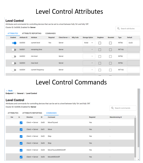
In our example let's say we have a light with the Level Control Cluster. The Light has a set of server side attributes which the device maintains. The commands available show the different commands a client such as a switch could send to the light. The light then would make changes to its attributes after it made some local control change.
A simplified light and switch example would be to take a look at the On/Off cluster. On the server side we have the On/Off attribute, this is the state of the light. The client would not need to store this value as it does not describe the device's state. The light can receive commands to change the On/Off attribute state, for example, On, Off, or Toggle. The ZCL covers all attributes and commands but an easy way to review functionality is by searching through the ZCL clusters using the Zigbee Cluster Configurator. The available commands are on the client side, our switch, that correspond to the functionality on the light. This way a light and switch that use the On/Off cluster can understand the messages sent and received.
| Server | Client | |
|---|---|---|
| Attribute | On/Off | None |
| Received Commands | On Off Toggle | None |
| Generated Commands | None | On Off Toggle |
Endpoints#
An endpoint is a service point on a Zigbee node. So, each endpoint implements a single device type from a single application profile. As an example, we could have a thermostat with 4 user defined endpoints. Endpoint 0 is the ZigBee Device Profile, or the ZDO endpoint. However, endpoint 1 could be an HA endpoint acting as a thermostat device, while endpoint 2 is also HA, but acting as an On/Off Output. Our third endpoint could be a Smart Energy profile, and could be an In-Home Display, while our last endpoint, endpoint 4, could be a proprietary endpoint. All of these device types would make up an application for one node.
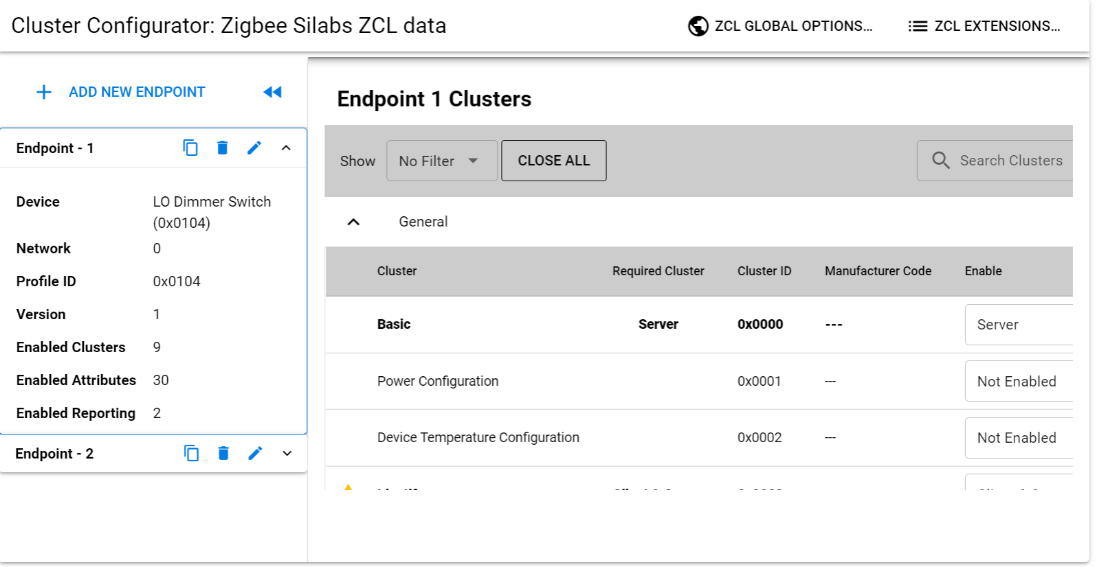
In the table below we have the endpoints for our Z3 Light Sample Application. Endpoint 1 is using the HA profile ID and is a LO Dimmable Light using a Centralized network configuration. Endpoint 2 is also using HA profile ID but is a LO Extended Color Light and is using the touchlinking (or decentralized) network configuration. The 3rd endpoint in this table has a special value of 242 which is reserved for the Green Power profile ID.
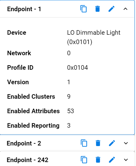
There can be, in theory, up to 255 endpoints defined within a node. However there is an endpoint 0 which is built in by the stack and reserved for Zigbee Device Objects, and endpoints 240 to 255 which are reserved for special future functions. This effectively leaves endpoints 1 through 239 for user applications.
Endpoint 0 is currently used as the ZigBee Device Object endpoint for network configuration and administration and is generally used by the stack for gaining information about other devices.
Endpoint 255 is used as a generic broadcast endpoint. So if you were attempting to send a message to a device, but were unsure which endpoint it was on, you could send to endpoint 255 of a node. In that case, it would be sent to all of the endpoints.
Each endpoint, when queried, will return a cluster list and a descriptor. The cluster list describes the capabilities of the device by enumerating supported client and server clusters. The descriptor contains information about which profile that endpoint is implementing, what the device ID is within that profile, how many supported client and server clusters it supports, and finally, it may contain a bitmask which indicates the version and capabilities of the application profile.
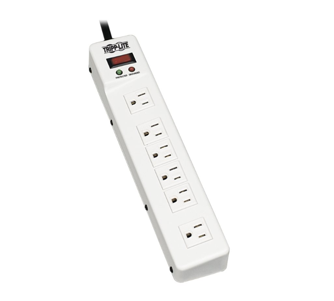
Another simplified example for multiple endpoints is a power strip. If a singular endpoint was implemented on this device, then it would be possible to turn the strip on and off. Let’s say you wanted to control each outlet individually. This would be a good case to add an endpoint for each outlet. This way it would be possible to turn on or off a singular powered device and not affecting all powered devices on the strip.
Device types#
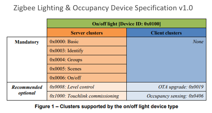
So which clusters and attributes do we implement on our device? As was hinted in the Endpoints section and the Z3 Light sample, the ZCL defines requirements for a device type. Each Device Type has a set of mandatory clusters so that any device reacts the same way at least for an obligatory set. It is always possible for a manufacturer to add optional functionality, but must be aware that optional functions may not be supported on all devices. In Figure 1 from the Zigbee Lighting and Occupancy Device Specification we see that an On/Off Light with Device ID 0x0100 has a set of Mandatory clusters and Recommended optional clusters.
Network Activities (Form, Join, Rejoin, Leave)#
Creating a Network#
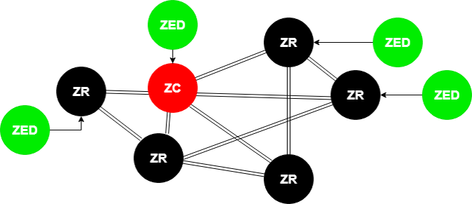
When a Zigbee network starts, it all begins with the Zigbee coordinator (ZC). This is shown in our diagram here.
The Zigbee coordinator (ZC) is represented by a thick red circle
The Zigbee Router (ZR) is represented by thin red circles
The Zigbee End Device (ZED) is represented by thin blue circles
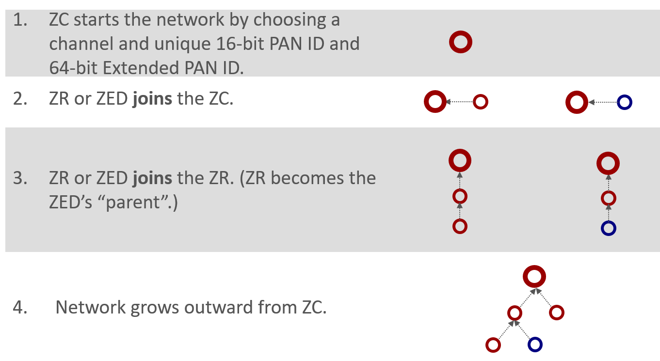
The coordinator begins by choosing a channel that would be one of the 2.4 GHz allocations designated 11 through 26. These represent channels with a center frequency from 2.405 GHz to 2.480 GHz. The coordinator is responsible for choosing a unique 2-byte PAN ID and a unique 64-bit extended PAN ID. If you recall from our last presentation regarding PAN IDs, the short PAN ID used to identify the network, but in case a conflict arises the extended PAN ID is the backup scheme.
Once the coordinator has chosen the channel, PAN ID, and extended PAN ID, the network expands by allowing more nodes, such as a router or an end device, to join through the existing coordinator. A device can only join the network through a node already on the network. The exception is the coordinator which is the device that forms the network.
After the first router joins the coordinator after network formation, future nodes can join the network through the coordinator or the new router. Nodes cannot join through an end device because an end device doesn’t have routing functionalities. As the network grows, a tree-like structure forms from the coordinator, with the end devices generally being on the fringes of the network.
Joining a Network#
From the perspective of joining a network - a device that wants to join the network is depicted by the purple circle. It is neither red nor blue because it hasn’t joined the network and therefore doesn’t have a node type.
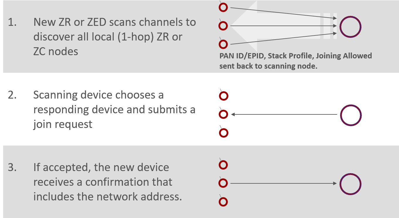
First of all the device has to scan across the channels, to identify what networks are available. Then it has to solicit router and coordinator nodes to determine which are available devices through which it can join. This process is called an Active Scan, an IEEE 802.15.4 MAC concept where we send the beacon request which is a single hop broadcast that transcends all the PAN ID boundaries. Every device in every 15.4 network within range can hear this beacon request, and they are supposed to respond with some indication of their network such as PAN ID, extended PAN ID and stack feature set, and a Boolean parameter that says whether or not there’s any joining allowed. This “joining-allowed” property is done on a case-by-case basis for each node. So it may be that there are two nodes in the available network but only one of those nodes is allowing new devices to enter. It’s something like having multiple access points into the network where they can be enabled or disabled for accessibility to new devices at will. The other information that’s not displayed in the diagram here is that there is also information from the router or coordinator about its ability to sustain additional end devices. So if you are an end device wanting to join the network, a potential parent might say it could let you into the network if you were a router, but because it can’t support any more end devices, it can’t let you in. This allows the end device to rule out that node as a potential parent.
In this diagram, in action number 1 we see the large arrow soliciting the devices with its beacon request, and the individual network indications are beacons coming back. Whichever beaconing device is heard best becomes the parent node of the joining device. Once this is chosen, the joining device submits an association request to the chosen node from the chosen network. This is action number 2 – the arrow going across to the chosen device. At this point there is no security authentication; it’s simply that if someone submits a join request to a node and it is permitting joining, and it can accept a new device, then it should create and send a random address to the joining device, and now the new device is successfully associated into the network. This is shown in action number 3. The process of association is a very simple one-to-one device process and doesn’t involve contact with other nodes. After the association takes place there is a security authentication step with the trust center device to complete the story, however, we will not provide details of this authentication as it is out of the scope of this introduction.
Network Analyzer Capture of Joining a Network#
Below is a log of the Network Analyzer to help illustrate the joining process. If you are not already familiar with this tool, we recommend that you take the time to learn about Network Analyzer.
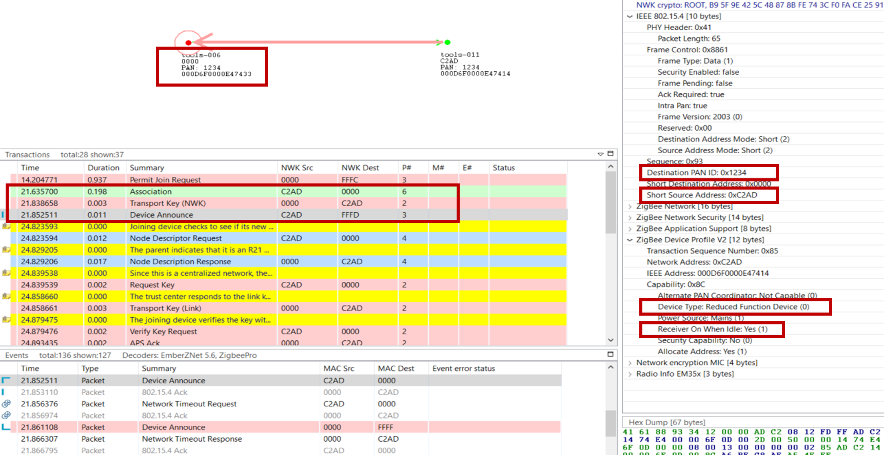
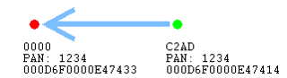
On the top, you see a visual representation of the network, and the arrows show the transaction between the nodes. The “Transactions View” shows all the transactions between nodes, and the “Event View” shows all the messages separately. This may be a bit overwhelming because the message of a transaction can be scattered over time. The “Events detail” view is showing the different fields inside the selected message in the “Events View”. More information about the Network Analyzer will be handled in the “Studio: Key Concepts Network Analyzer” presentation.
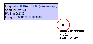
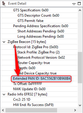
The joining device sends an association message to the coordinator of the network, this is the green message in the log. After this the coordinator will share the network key, so the device can encrypt and decrypt the messages. After this is done the joining device is announcing itself in the network, this way the whole network knows what kind of device the just joined device is. The details of the device announcement can be seen in the “Event Detail pane” on the right. Here we see in the top red box the PAN id of the network, also here is the short Id of the joined device visible. The following 2 red boxes are more device describing, from these boxed you can determine the device type, coordinator, router, end device, or a sleepy end device. Routers and Coordinators are full-function devices, while an end device or a sleepy end device are reduced-function devices. For a sleepy end device, the receiver will sleep when the device is in an idle state, while the other devices will always listen to the channel.
After Device Announce, the device requests a link key update. For further information and more details on link key update, see Zigbee 3.0 Security.
Rejoin a Network#
Rejoining is a way for a node to reconnect to a network of which it was previously part. Rejoining is necessary in three different circumstances:
Sleepy devices that may no longer be able to communicate with their parent.
Devices that have missed the network key update and need an updated copy of the network key.
Devices that have missed a PAN ID update and need to discover the network’s new PAN ID.
When a device tries to rejoin, it may or may not have the current network key. Without the correct network key, the device's request to rejoin is silently ignored by nearby routers. Therefore, a device has two choices when rejoining: a secured rejoin or a trust center rejoin. If the rejoining device has the correct network key it will do a secure rejoin to a neighboring router. A router/coordinator device will always provisionally accept a NWK layer Rejoin command with the active network key. If the network key is invalid the rejoining device will request a new network key from the trust center, this is called a Trust center rejoin. Note that neither of these rejoin cases requires the MAC Permit Association otherwise the procedure is the same as the Association procedure.
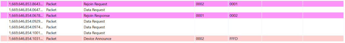
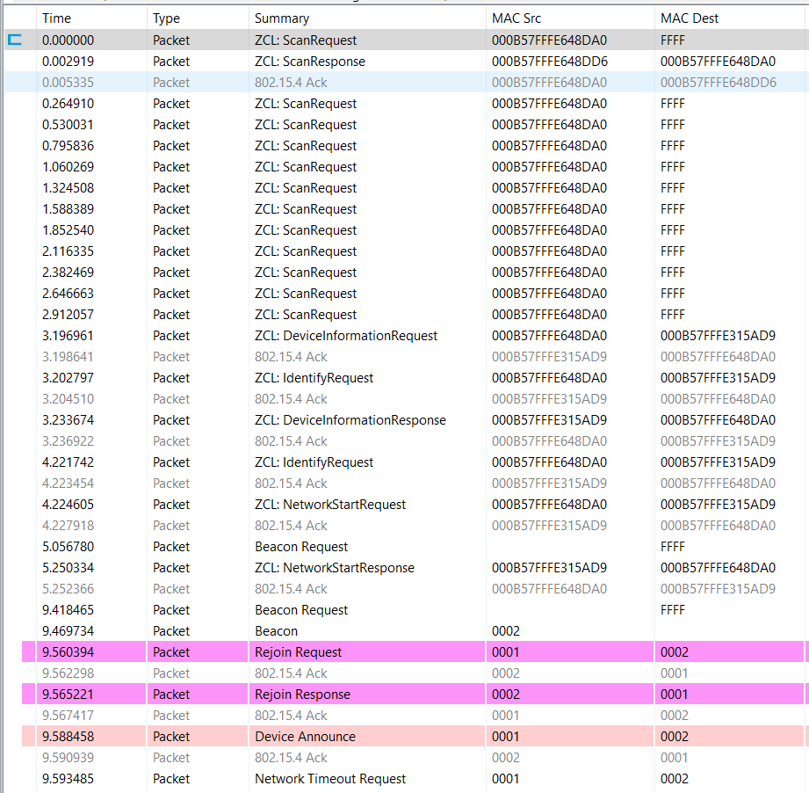
Let’s look at the above picture, this is part of a log from the Network Analyzer, where a device is sending a rejoin request to the coordinator. The coordinator is granting the device access to the network with a network response command. The message after this is a device announcement, this is used to notify that the device is on the network.
For a more detailed explanation, see Zigbee 3.0 Security.
Leaving a Network#
There are multiple ways to request a device to leave the network.
The ZDO leave command which can be indirect or direct. With the indirect way we request the parent of the end device to handle the leave of the end device. This can be useful with end devices. The direct way of a leave request will address the leave request to the device directly. This can be used for routers and end devices. (Note that messages for a sleepy end device may time out before they are delivered.)
APS Remove Device is another way to request a device to leave on the APS layer, this gives you the opportunity to encrypt the message.
If a device is receiving a leave request and then leaves, it sends a leave announcement to notify the rest of the network. This gives the opportunity to the rest of the network to take adequate actions, such as updating their routing tables.
The leave announcement can also be sent to the network as a result of device voluntarily leaving the network; here you can think of it as a graceful power down.
There are some example use cases of leaving a network and you can see below figure.
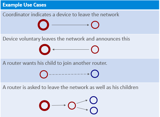
A coordinator that requests a device to leave the network, this is used for example when the joining process is not successfully completed.
A device that is voluntarily leaving the network. There the device is only sending the leave announcement.
A router that is requesting an end device to join another router; this can be a result of a router leaving the network and allowing its end device children to remain in the network.
A coordinator that is asking a router to leave the network, as well as its end device children. The router will first request the children to leave the network, and after that leave the network itself.
Example of ZDO Leave#
Let’s see how a network leave looks like in the Network Analyzer.
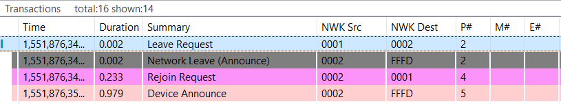
In the above figure you can see the transactions where a device is asked to leave and then rejoin the network. First, device 0x0001 is requesting device 0x0002 to leave the network.
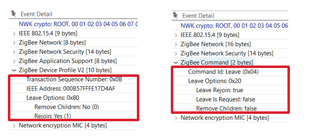
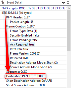
In the leave request, the Rejoin bit is set to True while the Remove Children bit isn’t set. This message is processed by device 0x0002 which sends a network leave announcement, the event details of which is shown on the right side. In this message we see that the Leave Rejoin bit is set, and other rejoin options are cleared. The “Leave is Request” is set when the device is leaving the network by a request; when it’s cleared the leave is initiated by the device itself. The Remove Children option bit is set when the children of the device are also removed, and cleared when this is not the case.
Node Types, PAN IDs, extended PAN IDs and Addressing in EmberZNet#
Node Types#
There are three node types in a zigbee mesh network. The differences among these types of nodes or devices mainly come down to their functionality and how they interact with other nodes in the network.
Zigbee Router (ZR): is the backbone of the mesh network as it is responsible for getting messages from A-to-B.
Zigbee end-devices (ZEDs): are leaf nodes to the mesh network with usually a router as a parent node. They can also be sleepy but more on that later.
Zigbee Coordinator (ZC): a router with added responsibilities to govern the network.
Whether the device should be Coordinator or a Router or an End Device/Sleepy End Device should be decided in the design phase of the application. Changing the device type dynamically is not supported and should be avoided. One exception is when a device is configured to be a router/coordinator. These devices can implement both the NetworkCreator and NetworkSteering plugins and if said device is creating a centralized network it shall become a coordinator. Otherwise, it can join another network as an end device.
Zigbee implementations before 3.0 do something similar with the Form and Join API calls.
Zigbee Router#
Zigbee Routers are mainly responsible for routing the messages of the mesh network. They can also act as end devices -> Have endpoints and added functionalities.
Line powered devices need to be chosen as Routers for the following reason:
Since routers are relaying messages they should be ready to receive messages all the time. They always need to be powered and never in low power mode with the radio offline. These devices should be planned to be powered as long as we want the network to function.
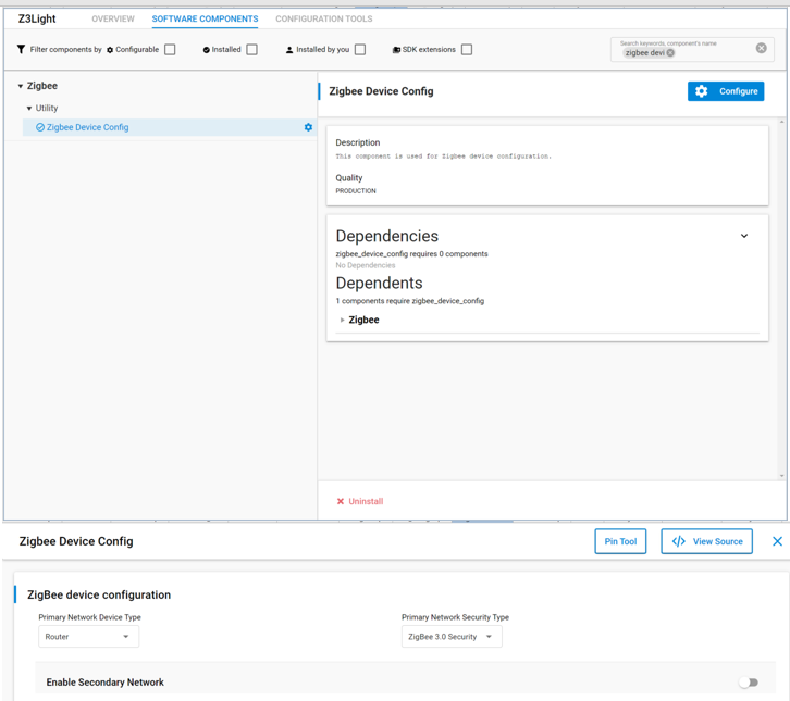
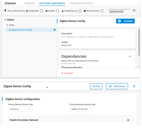
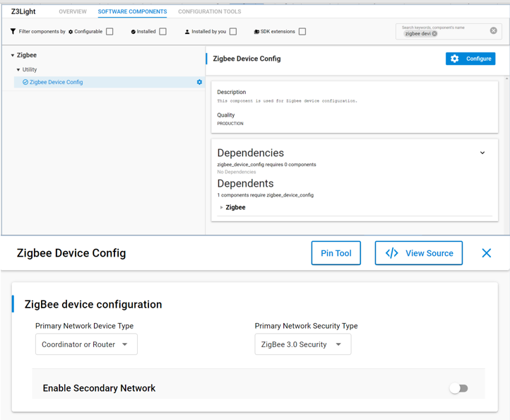
To setup a ZR in EmberZnet make sure you have selected Router as a device type by clicking configure in the Zigbee Device Config component. Also you must enable the Zigbee PRO stack library as a component as well.
Also you can configure the different buffers and tables associated with router functionalities by going to zigbee PRO stack Library and click configure.
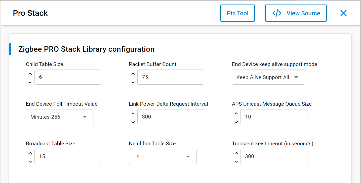
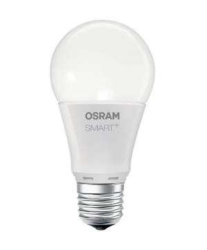
Typical example of a line powered router ZigBee device is a Smart Lightbulb.
Such devices are represented with a black dot in network analyzer.
Zigbee End Device#
End devices are devices that don’t participate in any routing.
The only concept of routing that they have is to send things to their parent or get things from their parent. When I say parent I mean there is a router node, this can be the coordinator, that is responsible for that end device, so it bears the responsibility of forwarding messages out and proxying messages in for that end device. An end device relies on its parent for communication to the network. If that communication is lost, the end device then has to go out and find a new parent, and re-attach itself to the network through this new parent.
To setup a ZR in EmberZnet make sure you have selected End device or sleepy end device as a device type by clicking configure of the Zigbee Device Config component.
Also you must enable the Zigbee PRO leaf library in the components tab as well.
You can see this contains similar options to the stack library it is basically a reduced stack library for end devices.
This is also the place where you can configure the different buffers and tables associated with end device functionalities.
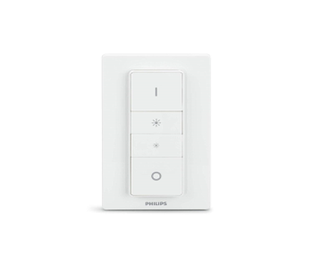
Typical example of a end device or sleepy end device is a wireless remote or switch for a smart light.
Such devices are represented with a green dot in network analyzer.
Zigbee Coordinator#
The coordinator is the most important part of the Centralized Zigbee Network. Only one coordinator is allowed per Network. It is the node that forms the network. The shortID of the coordinator is always 0x0000. The coordinator can also be a Trust Center (more on that in other modules) and network manager. This could be a Single Point of Failure -> Hence the TC backup and restore mechanisms.
In network analyzer the typical colors associated with the node type is red.
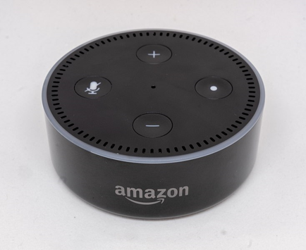
In the real world such devices are usually also part of gateways towards other parts of the world like the Amazon Echo.
Addressing in Zigbee#
PAN ID#
The PAN, or Personal Area Network, is separated from other networks through its PAN ID. This is a 16-bit identifier that all nodes in the same PAN will share. So it’s something akin to a subnet mask in the Ethernet world in that you generally would only be communicating with devices within your local network, which is the PAN in this case. This identifier is placed into the low-level MAC-layer header in every out-going packet, and it allows devices that receive the packet to filter out the messages that don’t pertain to their network.
They can compare it against their own PAN ID, and decide if this is a message from someone in their own network, or if it’s from someone in a different network that just happens to be on this channel so there’s no need to try to decode or decrypt it.
The PAN ID is chosen by the coordinator upon network formation. Because the PAN ID is the distinguishing factor between one network and another, it should be random to ensure its uniqueness. It’s recommended that you select a random 16-bit value for your PAN ID that keeps your network from coinciding with any other network that happens to exist in the area.
Now, what if you happened to pick a PAN ID that’s already used by another network? Or what if you did choose a random PAN ID that wasn’t in conflict with any other network, but later another network grew to overlap with yours? If the PAN ID conflict ever happens, the stack can detect such a conflict and can update its PAN ID automatically, and inform all the nodes in its network to move to the new PAN ID, so that each node can continue communicating with nodes in its original network and exclude anyone on the conflicting network. You may be wondering how the stack does this. The answer is it is done through the use of the extended PAN ID
Extended PAN ID#
Extended PAN ID is another network identifier known by all nodes in the PAN.
While the usual short 16-bit PAN ID is transmitted over the air in all the packets because it’s short and straightforward, the 64-bit extended PAN ID is rarely transmitted over the air. The extended PAN ID is also unique for every PAN, and it’s used as a backup criterion when the 16-bit PAN ID is not enough to always distinguish one network from another. For instance, when a PAN ID conflict occurs, you want to notify all devices in your network to move. You can distinguish your network from the conflicting network because the devices in your network all share the same extended PAN ID. The extended PAN ID is highly unlikely to conflict because it has 64 bits compared to the 16 bits in the short PAN ID.

The coordinator also chooses the extended PAN ID during network formation. It’s only sent over the air in response to an Active Scan when nodes are soliciting the network or when a PAN ID update is occurring.
It’s also a helpful factor in allowing you to select the network. If you are trying to come into a network rather than form one, you might wonder how to tell which networks are available. The way the networks are distinguishable from one another is not only in the PAN ID but also in the extended PAN ID. You might want to do something special where you decide you are only going to use a specific subset of extended PAN IDs so that you can distinguish your networks from other networks, but don’t limit yourself too much because the more you restrict this, the more likely that you have a conflict, and if your extended PAN ID ever conflicts there’s nothing you can do to fix that. It’s a little like a WiFi SSID, except those can be the same between networks, which this one can’t.
Node address#
Besides their network-wide criteria, one node is distinguished from another by its node addresses.
A node has a short address and a long address. The long address is the IEEE-assigned MAC address, or EUI-64. It is a 64-bit address that is globally unique, meaning no two IEEE-based radios in the world should ever have the same EUI-64. This is generally assigned at manufacturing time. They are set when the chips come out of our manufacturing facility before they arrive to you, and they will never change. That’s how you tell one radio from another. But because 64 bits are a lot of data, this long address is not often sent over the air.
Most of the time, the much shorter, 16-bit address is used over the air. This is known as the node ID and is unique within a network, similar to an IP address in the Ethernet world. It is assigned as the node enters the network, and it’s supposed to be unique within that network. There may be two networks, each of which has a node with the same node ID, but because they are in different PANs, it doesn’t matter.
Note that two nodes can have chosen the same random node ID when they enter the network. If that happens, much like the PAN ID scheme, there is a method for conflict resolution. Using the EUI-64 information as a fallback, the nodes can agree upon new addresses when they notice the conflict. So the nodes can change addresses at run-time, if required, based on a conflict.
In addition to addresses of the node, there are also concepts of addresses within the node. These are Endpoints and Clusters and are explained in the “Clusters Endpoints Devices” training module.
Overview of Zigbee Cluster Library (ZCL)#
Zigbee defines the MAC/PHY and Network layer standard and the application layer protocol - Zigbee Cluster Library. This training module focuses on the Zigbee Cluster Library. The specification is available for public download at csa-iot.org
Overview#
Cluster#
Represents a specific functionality through defined Attributes and Commands
Stresses a standardized message format for attributes and commands, which ensures interoperability that allows for ease of interoperable use between devices
Uses the “client” and “server” model of communication
Supports Manufacturer Extensions
Zigbee Cluster Library (ZCL)#
Is a repository for clusters for use in public profiles
The same cluster (and ID) can be used in multiple profiles
Attribute#
Key concepts in a cluster include data, messaging, and the direction of communication. An attribute is data associated with a cluster. Each attribute declares a 16-bit identifier, a data type, a read-only or read/write designator, a default value, and is supported by mandatory or optional.
The following table lists some of the attributes of the Temperature Measurement Cluster. The cluster server supports five attributes; the Tolerance attribute is optionally supported. These attributes are read-only, indicating that any write attempts to them will fail.
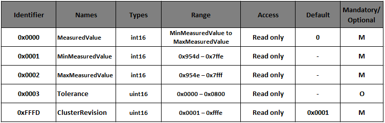
The Cluster Revision attribute is a global attribute introduced in revision 6 of the ZCL. The Global attributes are defined for every cluster instance on a device and function as standard ZCL attributes. This attribute is a way to version each cluster specification, improve backward compatibility, and allow testing of specific versioned cluster behavior. This Cluster Revision attribute is incremented for every major change to each cluster’s specification.
Command and Client-Server Model#
Commands are divided into two types according to their cluster scope: global and cluster-specific.
Global Commands are mainly used for manipulating the attributes (such as read, write and report attributes), and they are not specific to any cluster.
Cluster-Specific Commands are part of the cluster definition and include the payload format, support requirements (mandatory, optional), and behavior on receipt of a cluster-specific command. For example, the ZCL On/Off cluster defines three mandatory commands (OFF, ON, and TOGGLE) and several optional commands.
Each cluster has a distinction of a client and server side.
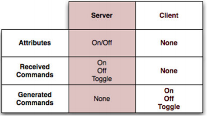
The server is the side that contains the Attributes. The client side is usually the one that reads and/or modifies the attributes. For example, in an On/Off cluster, the client side would typically be a switch that sends messages, such as on/off commands, to a server which would be a light. Being the server, the light would contain the On/Off attribute to indicate whether the device is on or off.
Manufacturer Extensions#
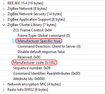
The ZCL allows extending the existing library in several ways. For example, users may add manufacturer-specific commands or attributes to existing clusters or define entirely new clusters that are manufacturer specific.
Manufacturer-specific commands are identified by setting a particular bit in the ZCL frame control and including the manufacturer code (received from the Zigbee Alliance) in the ZCL frame. This guarantees that manufacturer-specific extensions do not interfere with other manufacturer-specific extensions or existing ZCL clusters.
Manufacturer-specific clusters must use the cluster ID range of 0xFC00-0xFFFE.
Touchlink Commissioning#
As we know, touchlink commissioning is used in the ZLL network. It was initially developed to easily integrate devices in connected lighting systems that follow the ZigBee Light Link(legacy) standard. The idea of touchlink commissioning is to facilitate close physical proximity(approx. 10 cm) instead of cryptographic authentication.
Zigbee 3.0 inherited the touchlink commissioning procedure as an optional commissioning mechanism where nodes are commissioned on a network using commands sent using inter-PAN communication in close physical proximity.
The BDB specification describes there are four commissioning methods in Zigbee 3.0, the order are as follows:
Touchlink commissioning
Classical network joining
Classical network formation
Finding and binding
In here, touchlink commissioning is the first step in the ZigBee 3.0 network commissioning process.
A device may choose to perform the touchlink process for an initiator to try and find a touchlink target. A typical example of this interaction may be a switch and a light. The switch may perform touchlink commissioning to establish itself on the same network as the light.
Touchlink Commissioning Definitions#
Touchlinking Commissioning involves two parties, an “initiator”, who is the device (usually a controller of some sort) initiating the discovery process, and a “target”, who is the device (usually a light) being discovered. A device may choose to perform the touchlink process for an initiator to try and find a touchlink target.
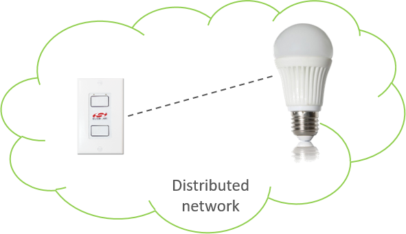
A device that does not contain any network parameters and is not part of a network is known as “factory new”. When a device is reset to “factory new”, its network parameters are erased. Conversely, a device that does contain network parameters and is part of the distributed network is known as “non factory new”.
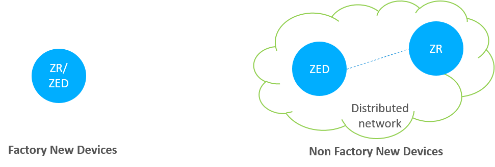
We can see the differences from the above figure. Once the device is a part of the network, then it is non factory new device.
Touchlink Commissioning Scenarios#
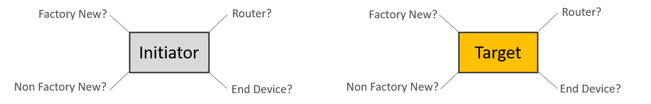
The commissioning mechanisms depend on whether the initiator is factory-new or non-factory-new. The initiator and target can be implemented from either an end device or a router, so there are many scenarios.
Here are some tips you should care:
If the initiator is factory new, it requests a new network to be started and if the initiator is non-factory new it requests the target to join its network.
If the target is non-factory new and already part of a network, it can be stolen onto the network of the initiator.
If the initiator is a factory new end device, it must be commissioned with a router target so that a new network can be formed.
However, the target can decide whether to accept a request to start a new network or join an existing network when requested to do so by the initiator.
Touchlink Commissioning Cluster#
The touchlink commissioning cluster shall have a cluster identifier of 0x1000 and it is comprised of two sets of commands to support touchlink commissioning:
One providing touchlink commissioning functionality
One providing commissioning utility functionality
The touchlink commissioning command set has command identifiers in the range 0x00-0x3f and shall be transmitted using the inter-PAN transmission service.
The commissioning utility command set has command identifiers in the range 0x40-0xff and shall be transmitted using the standard unicast transmission service, similar to that used for other ZCL cluster commands.
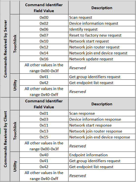
The above image shows that both the client and server contain the touchlink commissioning and commissioning utility commands. More details can be found in the Zigbee Cluster Library specification.
Device Discovery Procedure#
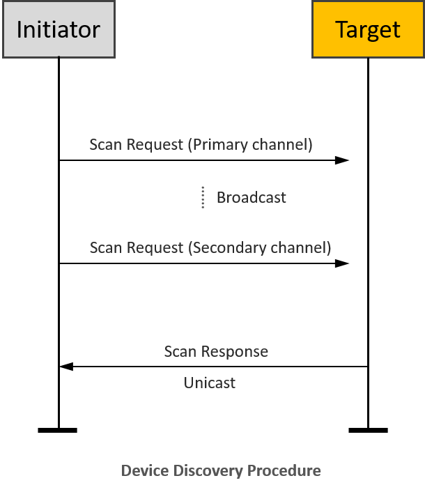
On the initiator side, device discovery begins with a broadcast of eight inter-PAN scan request command frames, with the touchlink initiator sub-field of the ZLL information field set to 1 and with a nominal output power of 0dBm. The transmission proceeds as follows:
The initiator switches to the first primary ZLL channel (i.e. channel 11) and broadcasts five consecutive scan request inter-PAN command frames.
The initiator then switches to the remaining three primary ZLL channels and broadcasts a single scan request command frame on each channel.
After each transmission, the initiator waits a fixed amount of time to receive any responses.
If an extended scan is required (i.e. for a reset to factory new or if the initiator is part of a non-ZLL network), the initiator switches to each of the secondary ZLL channels and broadcasts single scan request command frames on each channel, and waits to receive any responses.
Touchlink Commissioning inter-PAN Transaction#
All touchlink commissioning cluster inter-PAN command frames shall carry a 32-bit transaction identifier. The transaction identifier is created by the initiator of a scan request inter-PAN command frame and shall be random, non-zero and non-sequential. Related inter-PAN command frames which follow the scan request, i.e., scan response, device information request/response, identify request, reset to factory new request, network start request/response, network join router request/response, and network join end device request/response shall carry the same transaction identifier as was defined in the scan request.
Let’s introduce the function of the inter-PAN command frames:
The scan request command frame is used to initiate a scan for other devices in the vicinity of the originator. The information contained in this command frame relates to the scan request initiator.
The scan response command frame is used to respond to the originator of a scan request command frame with device details. The information contained in this command frame relates to the target that is responding to the scan request command frame.
The device information request command frame is used to request information regarding the sub-devices of a remote device.
The device information response command frame is used to return information about the sub-devices supported by a node.
Suppose the Profile Interop bit of the Touchlink Information field of the Scan Request command received at the beginning of the current touchlink exchange is set to zero. In that case, the device may represent its device information in the form of ZLL device information to support legacy devices. If this bit is set to one, the device shall use the device information as given in its simple descriptors.
The identify request command frame is used to request that the recipient identifies itself in some application specific way to aid with touchlinking.
The reset to factory new request command frame is used to request that the recipient resets itself back to its factory new state.
The network start request command frame is used by a factory new initiator to form a new network with a router.
The network start response command frame is used by a router to respond to a network start request command frame received from an end device.
The network join router request command frame is used by a non-factory-new initiator to join a router to its network.
The network join router response command frame is used by a router to respond to a network join router request command frame received from a non-factory-new end device.
The network join end device request command frame is used by a non-factory-new initiator to join a factory new end device to its network.
The network join end device response command frame is used by a factory new end device to respond to a network join end device request command frame received from a non-factory new end device.
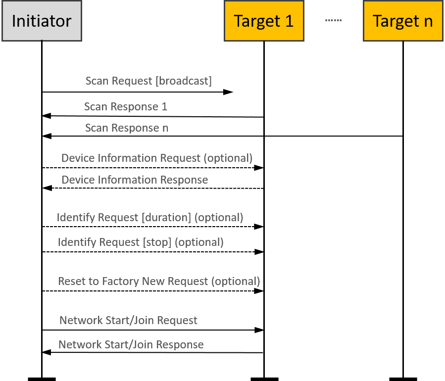
Please note that the “optional” in the flow chart means the command is not mandatory and can be added if needed during the Touchlink commissioning.
Touchlink Commissioning ZCL Transaction#
After the touchlink commissioning successfully, there are four kinds of ZCL commands can be used between the initiator and the target:
Network update request
Endpoint information
Get group identifiers request/response
Get endpoint list request/response
The network update request command frame is used to attempt to bring a router that may have missed a network update back onto the network. If an initiator finds a device during device discovery that is part of the same network as the initiator but that reports a network update identifier in its scan response inter-PAN command frame that is lower than that of the initiator, it may generate and transmit a network update request inter-PAN command frame to the target using the unicast data service. The target updates its stored network update identifier and logical channel with the values received in the network update request.
The endpoint information command is used to inform the remote endpoint about the general information of the local endpoint. This command may be a trigger for the remote endpoint to get more information from the local device using the other commands described as below.
A controller application endpoint may send an endpoint information command frame to another controller application endpoint to announce itself. It is then up to the recipient controller application endpoint to take further action to get information about the lights that the originator controls.
If it decides to do so, it can use the get group identifiers request command frame to gain knowledge about the group of lights controlled by the originator. The originator responds with a get group identifiers response command frame containing the requested information (which may have a start index field and a count field equal to 0, indicating no groups are used).
Similarly, the recipient device can use the get endpoint list request command frame to gain knowledge about the list of individual lights controlled by the originator. The originator responds with a get endpoint list response command frame containing the requested information (which may have a start index field and a count field equal to 0, indicating no lights are controlled).
Please note that the “optional” in here means these are mandatory for a controller device but not mandatory for other devices as defined in the device specification.
Typical scenarios#
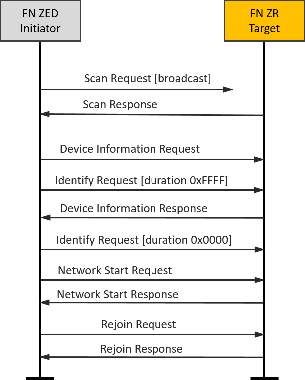
FN end device(Initiator)-FN router(Target)#
A typical scenario might be a new remote control and a new lamp being started for the first time.
It is easy to set up the testing with Z3Switch and Z3Light samples. After you build the samples and download the firmware into the WSTK kits, you can launch the console in Network Analyzer and use the below CLI command to reset the devices to factory new.
plugin zll-commissioning resetThen, move the two devices close to approx. 10 cm and click the button 0 on Z3Switch, it will make the Z3Switch device works as initiator to discovery the target. In here, you can also use the below CLI command to trigger the initiator to start device discovery procedure.
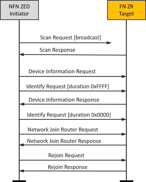
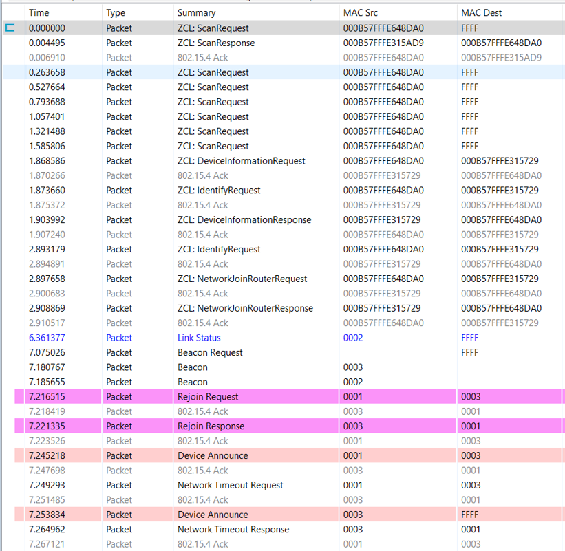
plugin zll-commissioning linkOnce the FN target responds the device discovery, the touchlink commissioning is starting. During this case the Z3Light will form a distributed network and the Z3Switch will rejoin to the network. The whole procedure is shown in the image and you will see the details in packet trace.
|
|
|---|
NFN end device(Initiator)-FN router(Target)#
Another typical scenario might be adding a new lamp to an existing lighting network.
It is easy to set up the testing based on the scenario one. After we finish the scenario one, the Z3Switch and Z3Light are in the same distributed network and they are non factory new devices.
Then, let’s build another Z3Light sample and download the firmware into another WSTK kit. As the same operation in scenario one, you can launch the console in Network Analyzer and use the below CLI command to reset this second Z3Light device to factory new.
plugin zll-commissioning resetAfter that, move the Z3Switch device and this second Z3Light device close to approx. 10 cm and use the below CLI command to trigger the Z3Switch to start device discovery procedure.
plugin zll-commissioning linkOnce the second Z3Light responds to the device discovery, the new touchlink commissioning starts. During this case, the second Z3Light target will join the pre-existing distributed network, and the Z3Switch device will rejoin the Z3Light. At last, you will find that all three devices are in the same distributed network and can talk to each other with ZCL commands. The whole procedure is shown in the image, and you will see the details in the packet trace.
|
|
|---|