Networking Concepts#
Address Table#
As we know, every device in the Zigbee network has its own EUI64 and node id. The address table is used for tracking the EUI64 and node id mapping for the other devices in the network. The benefit of the address table is to expedite unicast message sending by avoiding unnecessary network lookup queries when you send the unicast messages via address table. The address table is stored in RAM, so it is volatile and will be lost if the devices reboot. When you find some unicast failure caused by loss of address table entry, you may need to check if the device was rebooted or not.
As you can see, the content and structure of the address table is very straightforward. You may be very interested in how to use the address table. The address table is maintained by the network stack and can be modified in the application layer. The address table size can be configured in the Address Table plugin, which provides support for managing the address table with APIs. We can also send unicast messages via the address table. Let’s talk about it in detail.
Address Table Component#
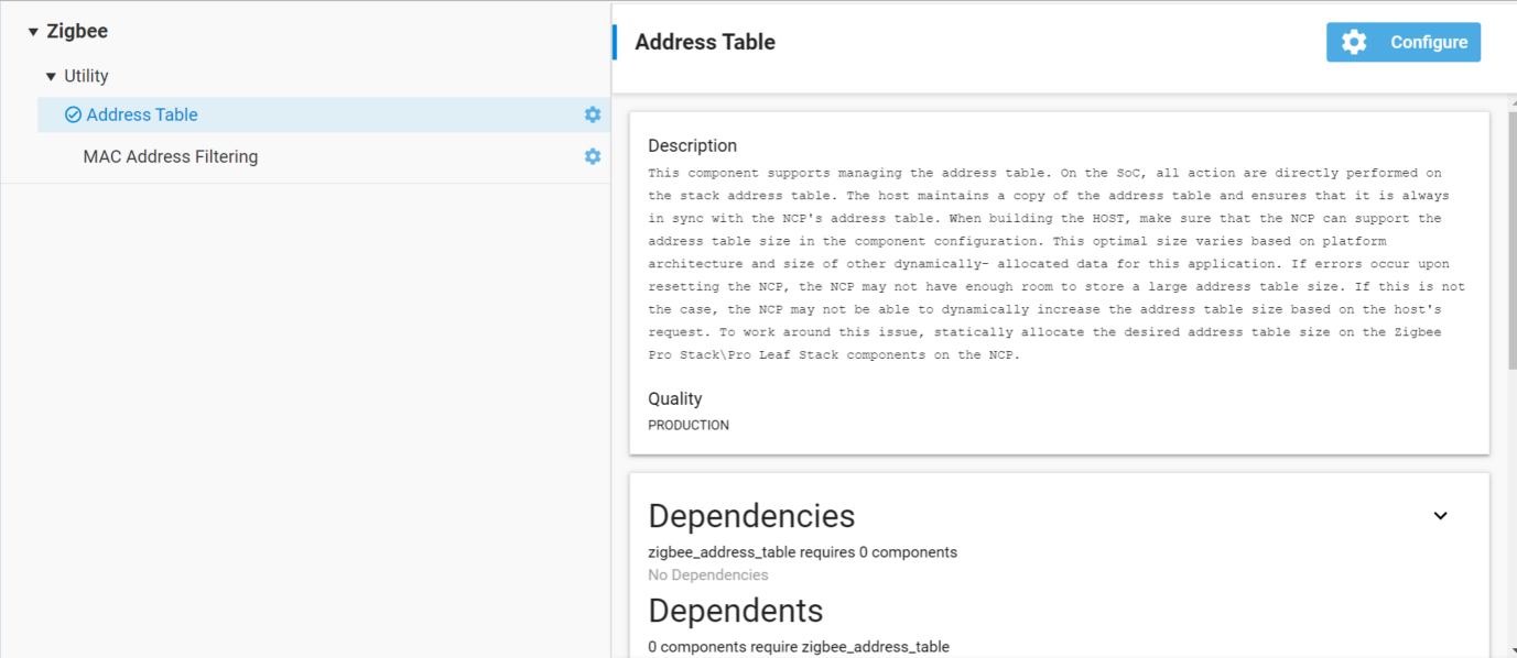
There is an Address Table component in the *.slcp file. This component provides support for managing the address table. As shown in the image, the address table is configurable. If one clicks into the configuration the address table default size is 2, but can be modified.
On SoC, all the actions are directly performed on the stack address table. On NCP, the Host maintains a copy of the address table and ensures that it is always in sync with the NCP's address table. When building for the HOST, the user should take care to make sure that the NCP can support their address table size selected below. This optimal size varies based on platform architecture and size of other dynamically allocated data for this application. If the user sees errors upon resetting the NCP, then it may be because there is not enough room on the NCP to store a very large address table.
Send Unicast via Address Table#
As mentioned before, one of the functions for the address table is when sending unicast messages. Messages can be sent using the address table by specifying the type as EMBER_OUTGOING_VIA_ADDRESS_TABLE in emberSendUnicast(). When we set the outgoing message type as EMBER_OUTGOING_VIA_ADDRESS_TABLE, it means the unicast sent using an entry in the address table to get the remote EUI64 and note id for the message. So we should make sure both the remote EUI64 and node id are valid in address table, otherwise it will get unicast failure. The other arguments like apsFrame contains the unicast message options and the buffer contains the message itself.
In a word, we can send unicast via address table if the address table entry exists and both the node id and EUI64 are valid.
EmberStatus emberSendUnicast(EmberOutgoingMessageType type,
uint16_t indexOrDestination,
EmberApsFrame *apsFrame,
EmberMessageBuffer message);@param type: Specifies the outgoing message type EMBER_OUTGOING_VIA_ADDRESS_TABLE.
@param indexOrDestination: The index into the address table.
@param apsFrame: The APS frame which is to be added to the message.
@param message: Contents of the message.
APIs of Address Table#
We provide Application Framework and Application Framework Plugin APIs and it is important to distinguish between them.
Application Framework APIs:
emberAfAddAddressTableEntry (EmberEUI64 longId, EmberNodeId shortId)
emberAfRemoveAddressTableEntry (uint8_t index)
emberAfSetAddressTableEntry (uint8_t index, EmberEUI64 longId, EmberNodeId shortId)
Application Framework Plugin APIs:
emberAfPluginAddressTableAddEntry(EmberEUI64 entry)
emberAfPluginAddressTableRemoveEntry (EmberEUI64 entry)
Both emberAfAddAddressTableEntry and emberAfPluginAddressTableAddEntry will add a table entry to the address table. The difference between the two is that the emberAfPluginAddressTableAddEntry will check to make sure it is empty before adding to it. If you are using the plugin you will want to use emberAfPluginAddressTableAddEntry. Otherwise you will want to use emberAfAddAddressTableEntry. If you use the latter, you will also want to use emberAfRemoveAddressTableEntry to remove the entries. The reason for this is because the plugin APIs keep track of the reference count. The reference count itself is used to stop you from setting an entry to a used position.
To summarize, if you are using the plugin, use emberAfPluginAddressTableAddEntry/emberAfPluginAddressTableRemoveEntry. Otherwise, use emberAfAddAddressTableEntry/emberAfRemoveAddressTableEntry and emberAfSetAddressTableEntry.
CLI Commands for Address Table#
We can use CLI commands to operate the address table after we enable the Address Table Plugin. It is very convenient to add/remove/set/lookup/print the address table during the debugging.
CLI commands | Description |
|---|---|
plugin address-table add [EUI64] | Add an entry to the address table. |
plugin address-table lookup [EUI64] | Lookup an entry in the address table. |
plugin address-table print | Prints the address table. |
plugin address-table remove [EUI64] | Remove an entry from the address table. |
plugin address-table set [Index] [EUI] [NodeId] | Set an entry in the address table according to the arguments specified. |
EZSP for Address Table#
Below are the EZSP commands of Address Table. For host, we can use these EZSP commands to operate the address table.
ID | EZSP enum | Description |
|---|---|---|
0x05 | EZSP_CONFIG_ADDRESS_TABLE_SIZE | The maximum number of EUI64 to network address associations that the stack can maintain for the application. |
0x19 | EZSP_CONFIG_TRUST_CENTER_ADDRESS_CACHE_SIZE | The maximum number of EUI64 to network address associations that the Trust Center can maintain. |
0x5B | EZSP_ADDRESS_TABLE_ENTRY_IS_ACTIVE | Indicates whether any messages are currently being sent using this address table entry. |
0x5C | EZSP_SET_ADDRESS_TABLE_REMOTE_EUI64 | Sets the EUI64 of an address table entry. |
0x5D | EZSP_SET_ADDRESS_TABLE_REMOTE_NODE_ID | Sets the short ID of an address table entry. |
0x5E | EZSP_GET_ADDRESS_TABLE_REMOTE_EUI64 | Gets the EUI64 of an address table entry. |
0x5F | EZSP_GET_ADDRESS_TABLE_REMOTE_NODE_ID | Gets the short ID of an address table entry. |
0x82 | EZSP_REPLACE_ADDRESS_TABLE_ENTRY | Replaces the EUI64, short ID and extended timeout setting of an address table entry. The previous EUI64, short ID and extended timeout setting are returned. |
Asymmetric Link Detection#
Asymmetric Links#
This section goes over the problem of asymmetric links and how Zigbee attempts to mitigate the issue.
It has been found that link asymmetry arises largely due to manufacturing differences in mesh products. The node differences can have:
A variance in transmit power,
A different receive sensitivity,
Overall component differences between each uniquely designed product.
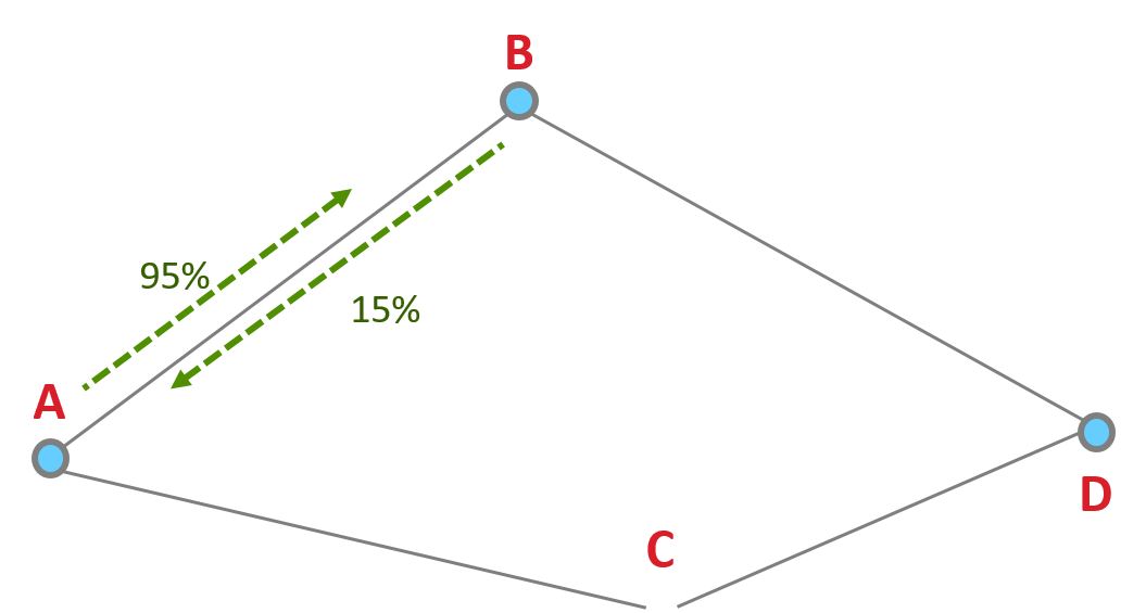
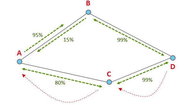
Zigbee routing discovers routes without regards to asymmetry, sometimes resulting in non-functioning routes. This is due to route replies traveling backwards on a discovered path. Zigbee route discovery uses links in one direction to discover a route in the opposite direction. Routing discovery assumes the quality of the link is the same in both directions when it actually could be different. For example, the quality in one direction of the link can be at 95% while the other direction the quality of the link can be 15%.
Asymmetric Link Detection#
To combat message delivery failures due to an asymmetric link, nodes need to find a reliable link in both directions. Routers will exchange link cost measurements with their neighbors by periodically sending out a Link Status message and collecting the information. The Link Status is a 1-hop broadcast message transmitted about every 15 seconds (+/- 1 second).
Lets say we have these four nodes.
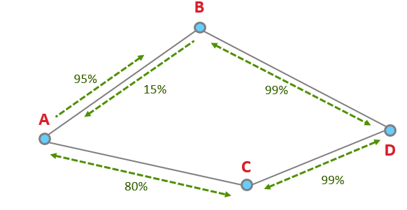
In this example, using only route discovery, the node will choose D to B to A, since it thinks the quality of A to B is 95%, vs A to C which is 80%. The node chose the worse route because of the asymmetry.
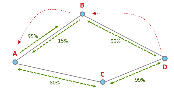
However, with Link Status Messages, the node is aware of the better route and will use the route with higher quality links in both directions: D to C to A.
Link Status Message#
Let’s take a look at an example of a Link Status Message.
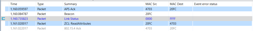
The above image is pulled from our Network Analyzer which breaks down a packet so that it is easier to consume. The coordinator (0x0000 in the fourth line) has sent out a Link Status broadcast. The event detail shows under the Zigbee command section that the coordinator only has one neighbor 0x20FC.
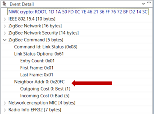
The link quality is assigned outgoing and incoming link cost in a rating from 1 to 5 where 1 is the best. Here the Outgoing Cost, meaning sending messages to 0x20FC has the best link quality, while the Incoming Cost, meaning receiving messages from 0x20FC has a bad link quality.
Please note, it is possible to get a cost of 0, which means the quality of the link is “unknown”. It can take two or three link status exchanges to get a good estimates of link quality between neighboring nodes.
Binding#
ZDO - Binding#
The binding command is part of a base class of functionality known as the Zigbee Device Object. The ZDO provides an interface between the application objects, the device profile, and the APS.
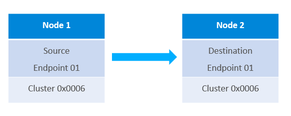
A binding creates a one-way link from one node to another node or from one node to a group of nodes that have a matching cluster. This is connected through the source and destination endpoints.
Once devices are on a network, devices can create bindings to establish application layer links.
For example a switch could have a binding for a light that it will always control. However, bindings are not required for Zigbee communication, but are useful for frequently used, persistent communication paths.
Binding Table#
The Binding Table maps control messages to their intended destinations. It stores the following information listed.
The binding index is the location of the entry in the binding table
The binding type is either a binding for a unicast message to one node or a group binding to several nodes in a group
The network index the binding belongs in. This is for devices that are in more than one network.
The Source Endpoint is the available local endpoint where the binding entry is available
The Destination Endpoint is the available endpoint on the remote device that the entry is pointing to.
The Cluster ID indicates the endpoint’s functionality bound to this particular remote node
The Destination Node ID is the remote node’s short address
The Destination EUI64 will either store the remote node’s long address if it is a unicast binding or a 16-bit multicast group address if the binding type is set as “group”
The addition or deletion of entries is managed completely by the application and is stored in non-volatile memory. The stack will not perform these actions automatically for any reason. The only action taken by the stack about the binding table is to update the information about the node ID in correspondence with the EUI64 destination for a binding table entry.
APIs to manipulate the binding table can be found in stack/include/binding-table.h.
Bind Request CLI Command#
Let’s take a look at a CLI command to understand the requirements for a Bind Request. The following CLI command ZDO Bind can be sent from any node. This is an over-the-air command.
ZDO Bind has the following arguments:
The “destination Node ID” is set to the node that will be receiving this ZDO command. This is where the binding will be created.
The “Remote device’s source endpoint” is the endpoint on the node that will create the binding and send messages through this binding.
The “Remote endpoint to bind” is the endpoint on the node that will be receiving messages through the binding.
The "cluster" that the binding is to be used for.
The “Remote node EUI64” is the device’s EUI64 that is receiving messages through the binding.
The “Binding’s destination EUI64” is the node where the binding is created.
Please note, since the binding is unidirectional, both sides do not need to be aware of the binding. Just the node that will be sending messages through the binding. Also, it is possible to create the bindings locally by adding an entry to the binding table. For creating a binding locally, you can use “option binding-table set”.
We also have a related KBA found here: https://www.silabs.com/community/wireless/zigbee-and-thread/knowledge-base.entry.html/2017/12/28/creating_bindingsan-egzv
Binding examples#
Light requesting the creation of a binding on the switch for the light#
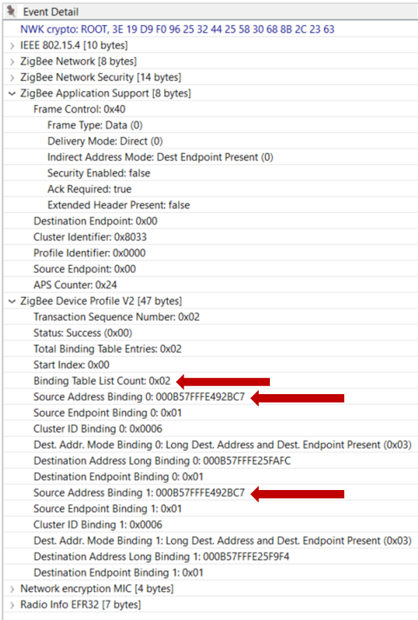
In this example we set up a binding for the On/Off cluster between a light and switch. The command is sent from 0x0000, which in this case is the coordinator and the light, to 0x6D92 the Switch.
Node ID of the switch: 0x6D92 Coordinator ID: 0x0000 On / Off Cluster: 0x0006 Switch EUI64: 000B57FFFE492BC7 Light EUI64: 000B57FFFE25F9F4
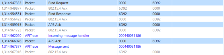
The Event Detail shows the request and the arguments are found under the Zigbee Device Profile section.
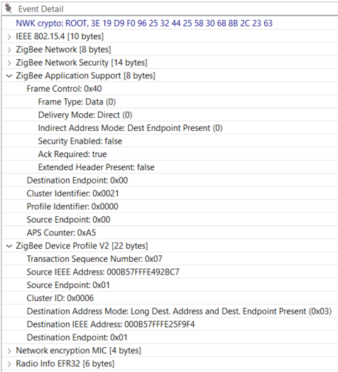
Also, a good way to check this is a ZDO command is to verify the Destination and Source Endpoints are set to 0x00 under the Zigbee Application Support section.
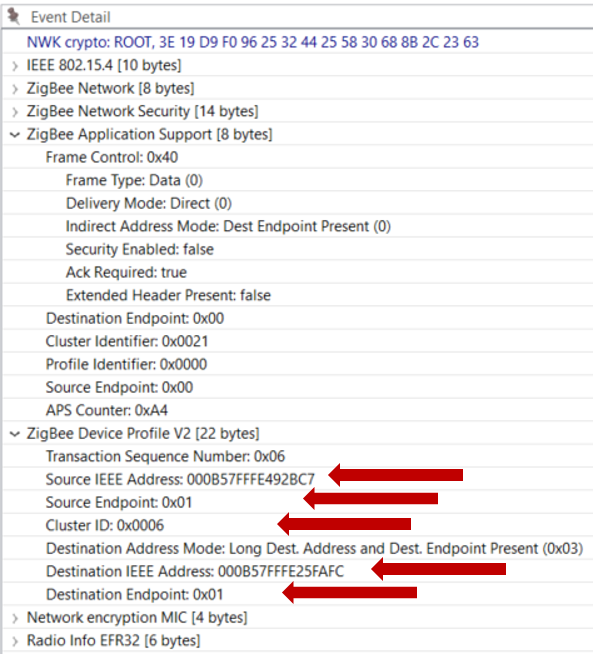
Coordinator requesting the creation of a binding on the switch for another light#
In this example we set up a binding for the On/Off cluster between a different light and the same switch.
Node ID of the switch: 0x6D92 Coordinator ID: 0x0000 On / Off Cluster: 0x0006 Switch EUI64: 000B57FFFE492BC7 Light EUI64: 000B57FFFE25FAFC
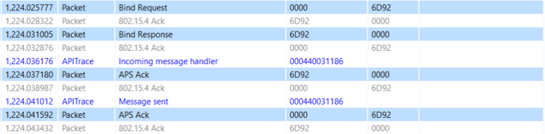
The command is still sent from the coordinator to the switch 0x6D92, but the binding is for another Light. Notice the different destination IEEE addresses between the examples.
Binding Table Request CLI Command#
EmberZNet also has a CLI command available for querying our switch about what is in its binding table.
zdo mgmt -bind <int16u> <int8u>The first argument here is the node ID of the device that has the binding table
The second argument is the first entry you want to see plus all entries after it.
For example the following binding request starts the query from 0x00 and iterates down the table.
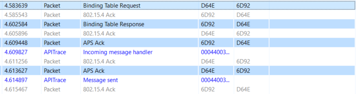
The Binding Table Response is shown in the Event Detail.
Notice the number of entries in the table and the two bindings that were created in the previous examples.
End Devices and Polling#
End Devices#
In a Zigbee network, there are three types of devices: Coordinators, routers and end devices.
End devices are leaf nodes. They communicate only through their parent nodes and, unlike router devices, cannot relay messages intended for other nodes. They don’t participate in any routing. End devices rely on their parent routers to send and receive messages. End devices that do not have tight power consumption requirements may choose to have their radio on at all times. These end devices are known as RX-on-when-idle devices.
The Sleepy End Device is a special kind of end device, that turns off its radio when idle, which makes it a suitable choice for battery operated devices.
Polling#
Now that we are familiar with end-devices, lets talk about polling.
Polling is the event wherein an end device sends a “data request message” to its parent node.
Polling has 2 main purposes :
KEEP ALIVE : End devices poll their parent nodes periodically as a keep-alive mechanism to prevent being aged out of the network.
REQUEST MESSAGES: On the sleepy end device, polling is additionally used to request messages sent to it that are held by the parent node.
The Long Poll Interval represents the maximum amount of time between MAC Data Requests from the end device to its parent. When the device does not need to be responsive on the network, it polls its parent on the LONG_POLL interval.
The Short Poll Interval : When a device needs to be responsive to messages being sent to it from the network, it goes into a state where it polls its parent on the SHORT_POLL interval. This ensures that any messages received by its parent will immediately be retrieved by the sleepy end device and processed. The time during which the sleepy end device is polling at the SHORT_POLL interval is referred to as “Fast Polling mode”. When the device expects data (such as the zcl/zdo message responses, etc.), it enters fast polling mode. Sometimes a sleepy device needs to stay in fast poll mode while sending a complex series of messages that constitute a complete application level transaction with another device. The usage of this API is documented in app/framework/include/af.h.
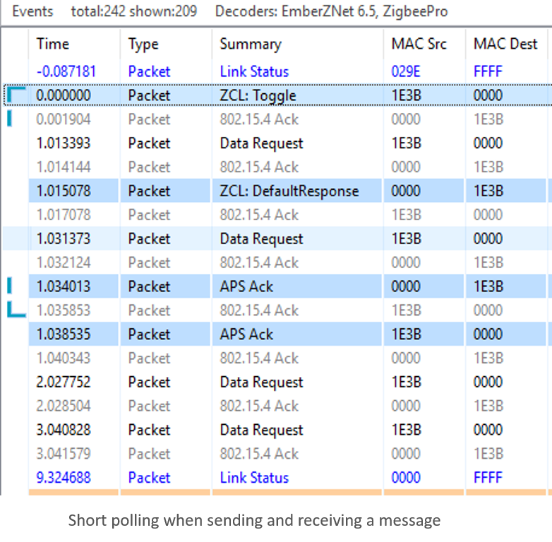
The packet trace below was captured using the Silicon Labs Network Analyzer. It shows the end device polling its parent at the short poll interval (1 second) for 3 seconds (which is determined by Wake timeout) after sending a ZCL toggle command and expecting the default response.
Poll Control cluster provides a mechanism for the management of an end device’s data polling rate with ZCL command. the details of Poll Control cluster are discussed further in a separate training module (App Layer: Poll Control Cluster).
Polling as a keep-alive mechanism#
Mac Data Polling is used as the keep-alive message between the child and parent.
End devices have to poll their parent at least once within the End Device Poll Timeout (as set by EMBER_END_DEVICE_POLL_TIMEOUT or EZSP_CONFIG_END_DEVICE_POLL_TIMEOUT). Otherwise, these devices will be removed from the child table of the parent, effectively being aged out of the network. This is done to ensure that the child table slot is not permanently reserved for an end device that has been removed from the network ungracefully (i.e., if no Leave notification was heard from that device. Leave notifications are broadcasts and are not guaranteed to be received);
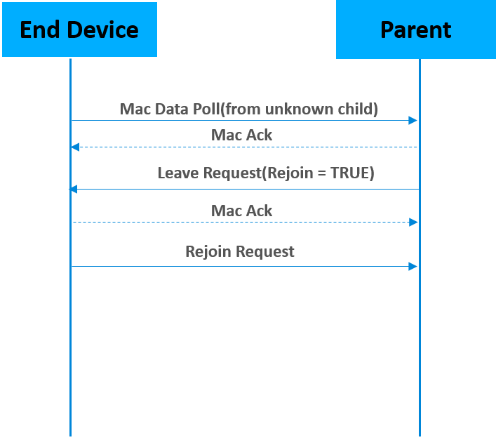
The parent node will ask the end device to leave and rejoin the network if it receives a mac data poll from the end device which doesn’t exist in the child table. The figure above illustrates the leave and rejoin process. In addition to this, if the data polling message isn’t acknowledged by the parent for EMBER_AF_PLUGIN_END_DEVICE_SUPPORT_MAX_MISSED_POLLS times, the end device will attempt to rejoin the network to find a new parent.
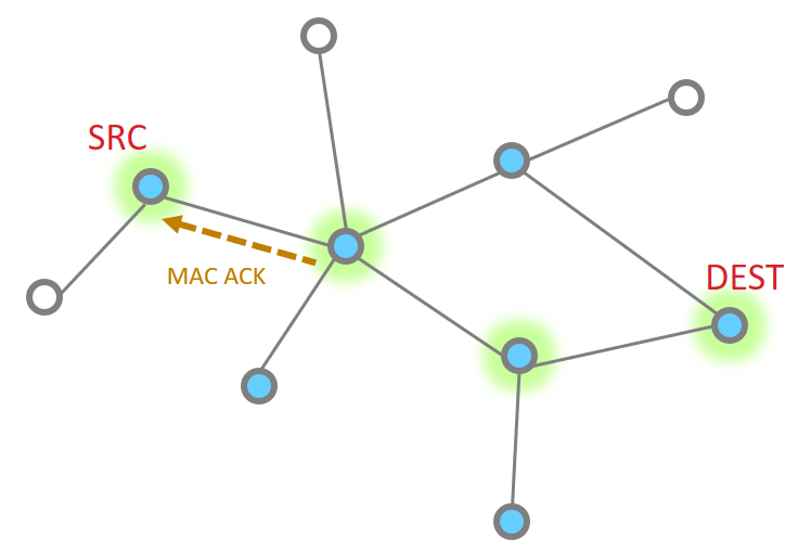
Polling as a means to request data from the parent#
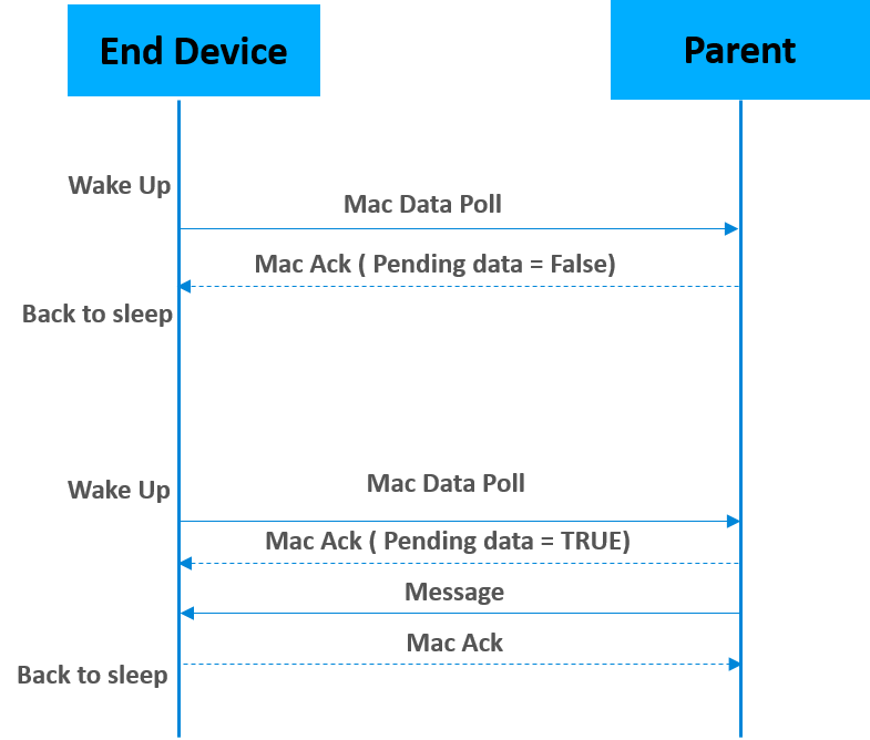
Sleepy end devices do not receive data directly from other devices on the network. Instead, they must poll their parent for data and receive the data from their parent. The parent acts as a surrogate for the sleepy device, staying awake and buffering messages while the child sleeps.
The figure below illustrates the data polling process. Sleepy end devices wake up and poll their parents at regular intervals. The parent node uses the Frame Pending bit in the MAC ACK to indicate that it has one or more messages waiting for the sleepy end device. If the Frame Pending bit is set to true, the sleepy end device will poll it's parent again and wait for the parent to respond with new data, and ack the data messages before going to sleep. If it is false, the sleepy end device is free to go back to sleep until the next poll attempt.
Please keep in mind that if you want the device to receive incoming messages and incoming APS ACKs (for its outgoing messages) reliably, you should poll at least once within the EMBER_INDIRECT_TRANSMISSION_TIMEOUT (7.68 seconds by default) to check for data at the parent because the length of time that the parent will hold on to a message is determined by this number. Some sleepy end devices (such as sensors) are not expected to asynchronously receive messages, so they don’t have the above limitation. They just need to poll within the end device poll timeout.
Application Design Considerations#
While the end device polling is supported at the Zigbee networking layer, you do need additional application layer support to configure polling parameters. Ex: how often to poll the parent, etc.
End device poll timeout can be set on both End device and parent device end.
End Device Configuration:
End Device Support Component
Long poll interval
Short poll interval
Wake timeout
Wake timeout bit mask
ZigBee PRO Leaf Stack Component
End device poll timeout value
Parent Device Configuration:
EMBER_INDIRECT_TRANSMISSION_TIMEOUT
ZigBee PRO Stack Component
End device poll timeout value
As we discussed previously, the Long Poll Interval should be less than EMBER_INDIRECT_TRANSMISSION_TIMEOUT if you want the device to reliably receive incoming messages and incoming APS ACKs (for its outgoing messages). Long Poll Interval should also be less than End device poll timeout to avoid being aged out by the parent which results in unnecessary rejoins. Generally, the SHORT_POLL interval will be something less than/or equal to 1 second to ensure that all messages can be retrieved and processed by the sleepy end device immediately.
Wake timeout is the amount of time (3 seconds by default) that the device will stay in the fast poll mode if the task set in wake timeout bitmask is active. For example, if EMBER_AF_WAITING_FOR_ZCL_RESPONSE (0x00000010) is set in wake timeout bitmask, the sleepy end device will stay in short/fast poll mode for 3 seconds when waiting for the zcl response. For more information about the Application Task in bitmask, please refer to enum EmberAfApplicationTask defined in af-types.h
End Device Poll Timeout Negotiation#
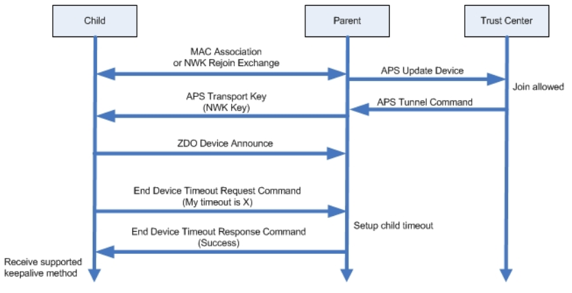
Zigbee R21 Specification offers an end device timeout negotiation protocol and a standard way to implement child aging. The End Device Timeout Request command is sent by an end device to inform the parent of its timeout value when joining/rejoining the network. When the parent receives this command, it will update the End Device Timeout value for this end device locally and generate an End Device Timeout Response command with a status of SUCCESS. Pre-R21 devices do not support End Device Timeout command. So they can only use the default End Device Timeout value set initially on the parent node.
Messaging (Unicast, Broadcast, and Multicast)#
Before you start this training module, we strongly recommend that you get familiar with these training modules first:
Zigbee Introduction: Node Types, PAN IDs, Addresses
Zigbee Networking Concepts - Binding
Zigbee Networking Concepts - Routing
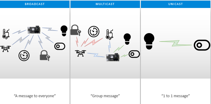
Message Types#
There are three major message types, include: Broadcast, Multicast and Unicast.
Unicast: The transmission of a message to a single device in the network.
Multicast: A transmission to every device in a particular PAN belonging to a dynamically defined multicast group.
Broadcast: The transmission of a message to every device in a particular PAN belonging to one of a small number of statically defined broadcast groups, for example all routers or all nodes.
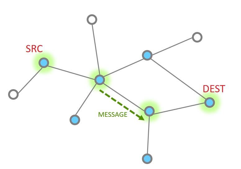
Unicast#
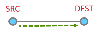
The unicast is a message that is directed from one node to another node. At it’s most basic level, the unicast is just a message sent between two adjacent nodes.
However, they can be much more complicated, being routed through 1 or more additional nodes through the network.
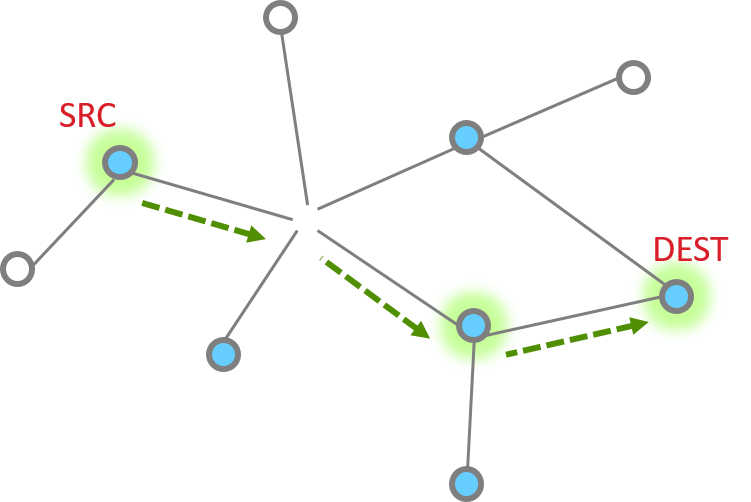
The unicast message can be sent by API emberAfSendUnicast().
Regarding how to route the message to the destination node, please review the Networking Concepts - Routing and Networking Concepts - MTORR Source Route training module.
Unicast Message Delivery#
Single hop message#
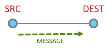
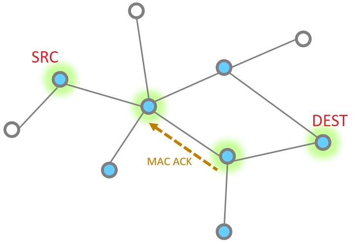
So let’s look at the basic message between two nodes, since this is most simple. This is the building block from which all other messaging is done.
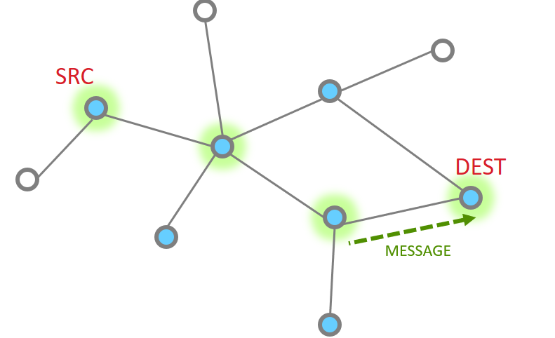
When it works perfectly, single hop message delivery is a two part process with 4 steps total. Within 802.15.4 there are MAC acks for point to point jumps. Zigbee applies Application level acknowledgments to ensure end to end delivery.
So we start out with a message being sent Message Sent
This message then is acknowledged at the MAC layer
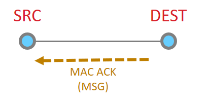
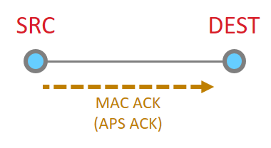
Since the message has been sent all the way to it’s destination, and it is requested, we must now get the application ACK. So this is now sent by the destination.
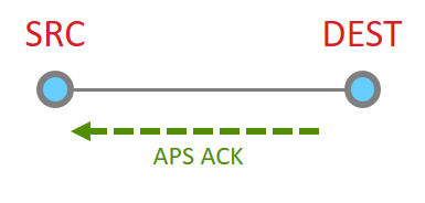
Since this is another 15.4 message, there has to be a point to point acknowledgement
And that is the whole process.
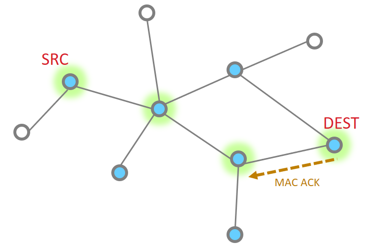
Multiple hops#
More nodes end up with more steps, but as a whole the process is the same, just longer. Instead the message traverses along being MAC ack’d until it reaches its destination and then an APS ack returns down the same route with each hop being MAC Ack’d.
The message is sent
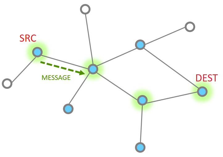
The point to point MAC Ack is received

Since our message has not made the final destination, it continues Next hop of the message and the MAC ACK
|
|
And one more hope to get to the destination
So then our App layer must send an acknowledgement. This is just like the message
|
|


The APS ACK is send backwards, with each step being MAC ACK’d
What happens if a message has a failure along part of this route? The EmberZNet stack has retry mechanisms in place to help resolve issues and ensure delivery. The MAC retries are 802.15.4 mechanisms that ensure delivery from point to point. If a MAC ack is not received, the MAC layer will automatically try sending the packet again. Failure at this level is around 40mSec EmberZNet further adds NWK layer retries. It is a timer up to 500mSec that retries MAC layer messages (point to point). These happen should the MAC retries fail. Finally there are APS retries, these are application layer acknowledgements which are designed to ensure messages are delivered end to end. Should an APS retry not be received, then the application will attempt to transmit a message again, following the steps above as before. The APS retry is a optional feature which can be configured by APS options EMBER_APS_OPTION_RETRY. We will discuss more APS option in the later.
Broadcast#
In Broadcast, The source node sends the message to all nodes in its 1-hop-range and these nodes repeat the message to all nodes in their 1-hop-range until the message gets to all nodes in a specific radius. In a large network, it would be difficult and unnecessary to expect all the devices that receive a broadcast message to send an acknowledgment back to the message originator, Instead a rebroadcast message is an indication of the fact that a neighbor device has received and relayed the broadcast message successfully. the source node verifies whether all of the neighboring devices have successfully relayed the message. This is known as the passive acknowledgment mechanism. Every time a broadcast message is repeated, the radius field is decremented and broadcast messages with a radius field set to 0 are not repeated anymore. Broadcast messages are jittered to reduce possibility of collision.
The routers maintain the record of all the messages that they broadcast in a table called the broadcast transaction table (BTT).
BROADCAST ADDRESS | DESTINATION GROUP |
|---|---|
0xFFFF | All devices on PAN |
0xFFFD | All non-sleepy devices |
0xFFFC | All routing capable devices |
The record itself is known as the broadcast transaction record (BTR) and contains the sequence number and the source address of the broadcast frame which helps in retransmission of the broadcasts. So in a given window of time, the number of broadcasts is limited by the broadcast transaction table size. In the EmberZnet, the broadcast table size can be configured in Zigbee Pro Stack Component.
While broadcast message sounds simple, it can significantly increase the traffic in the network, cause congestion and degrade performance. They should be used sparingly and with careful consideration.
Network-level broadcast options(broadcast address) exist to send messages to routers only, to all non-sleeping nodes including end devices, or also to send to sleeping end devices. End devices unicast their broadcast message to their parent node which in turn propagates the message through the network on their behalf.
The broadcast message can be sent by API emberAfSendBroadcast ().
Multicast#
In multicast, the message is delivered to a group of devices within the same network, it is a filtered limited broadcast. The picture below illustrates that, only member device can receive the multicast message in application layer.
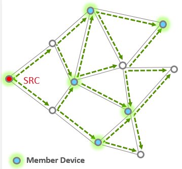
The source node does not have to be a member of a multicast group to be able to use multicasting to reach the members. Multicast messages may be originated by end devices but are not sent to devices where macRxOnWhenIdle is equal to FALSE.
Each group is identified by a 16-bit multicast group ID. The devices in the same group are known as group members. A device can be a member of more than one multicast group. Each device keeps the list of its multicast group memberships in a table called the multicast/group table
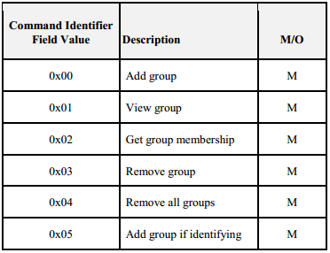
Groups usually managed via ZCL Groups cluster (see Groups client & server plugins and Zigbee cluster library Specification for more information). The table above shows the commands supported by the Group cluster.
The multicast message can be sent by API emberAfSendMulticast().
APS option#
Here are some commonly used aps option which can be configured when filling the aps frame. The structure of APS frame is shown below
typedef struct {
uint16_t profileId
uint16_t clusterId
uint8_t sourceEndpoint;
uint8_t destinationEndpoint
EmberApsOption options
uint16_t groupId;
uint8_t sequence; uint8_t radius;
} EmberApsFrame;
EMBER_APS_OPTION_ENCRYPTION: Send the message using APS Encryption using the Link Key shared with the destination node to encrypt the data at the APS Level. You can enable this bit mask if the APS data needs to be encrypted.
EMBER_APS_OPTION_ENABLE_ROUTE_DISCOVERY: Send the message with the NWK 'enable route discovery' flag, which causes a route discovery to be initiated if no route to the destination is known.
EMBER_APS_OPTION_RETRY: Resend the message using the APS retry mechanism. This option and the enable route discovery option must be enabled for an existing route to be repaired automatically
EMBER_APS_OPTION_ENABLE_ADDRESS_DISCOVERY: Send a ZDO request to discover the node ID of the destination if it is not already known. This option should be enabled if sending message via binding table.
EMBER_APS_OPTION_FRAGMENT: This option indicate the message is part of a fragmented message. For more information about the fragmentation feature please refer to fragmentation plugin.
For more APS options please refer to ember-types.h file.
Many-to-One and Source Routing#
Before you start this training module, we strongly recommend that you get familiar with these training modules first:
Zigbee Introduction: Architecture Basics
Zigbee Introduction: Node Types, PAN IDs, Addresses
Zigbee Networking: Unicast
Zigbee Networking: Routing (traditional)
Routing#
How do you send a message from one node to another in Zigbee?
Routing will help you answer this question.
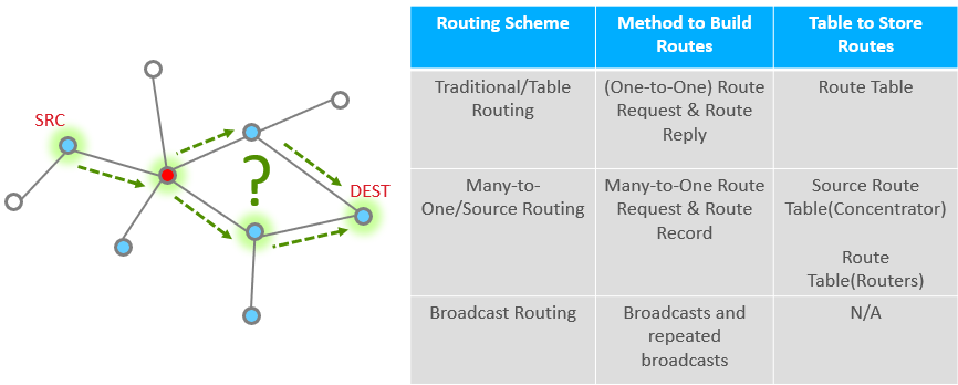
We have several types of routing commonly used in Zigbee:
Table routing (also considered the “traditional” routing scheme): you look up the routing table to find the entry matching your destination. This entry would tell you who is the immediate next hop to go to, in order to reach your final destination. This topic is covered in a separate training module, “Zigbee Networking Concepts: Introduction to Routing (Traditional)”.
Source Routing: in many Zigbee networks there is commonly one central node, a “concentrator”, which all nodes frequently communicate with. For example, a gateway that collects status reports from all devices in the network. In this training module we focus on a routing scheme efficient in the many-to-one and one-to-many communication pattern: Source Routing, and the accompanying many-to-one route request and many-to-one routing.
Broadcast routing: nodes not in 1-hop range of the transmitter rely on repeated broadcasts to get messages. While this is simple and does not require any routing algorithm, the obvious drawback is that it’s enormously inefficient. In a dense network, broadcast messages can quickly “flood” the network. Broadcasts should be used sparingly and with good consideration.
Routing Scheme | Method to Build Routes | Table to Store Routes |
|---|---|---|
Traditional/Table Routing | (One-to-One) Route Discovery (outgoing), and Route Reply (incoming) | Route Table |
Many-to-One/Source Routing | Many-to-One Route Request (outgoing), and Route Record (incoming) | Route Table; Source Route Table |
Broadcast Routing | Broadcasts and repeated broadcasts | N/A |
Why Many-to-One and Source Routing#
Assuming that you are familiar with traditional/table routing, we will now introduce Many-to-One and Source Routing and explain why this has some advantages in certain types of networks.
First let’s introduce the concept of a “concentrator”. Imagine a common smart home network where you have a number of smart lights, appliances, sensors etc., and a gateway through which the devices can communicate with the outside world. These devices would periodically send status updates to the gateway. This creates a frequent many-to-one message pattern. This gateway is a “concentrator” in such a network since messages tend to flow toward it. Since the concentrator needs to acknowledge these messages as well as potentially send further responses and commands to devices, the one-to-many messaging also naturally becomes frequent.
Many-to-One routing, as the name suggests, is a special type of routing that makes it efficient for devices to establish routes inbound to the concentrator. Each device stores the many-to-one route information in its regular route table, with a flag to mark it as a many-to-one route. The reverse route of a many-to-one route is a source route, which the concentrator then uses to get back to the outlying device. The source route information is stored in a source route table on the concentrator only.
Next, let’s examine the specific steps in establishing routes using many-to-one and source routing.
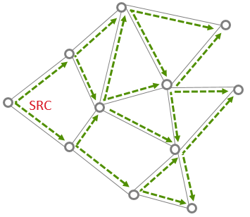
How to Establish Many-to-One / Source Routing#
There are three main steps or components of establishing many-to-one and source routing, which you can consider as two sides of the same coin.
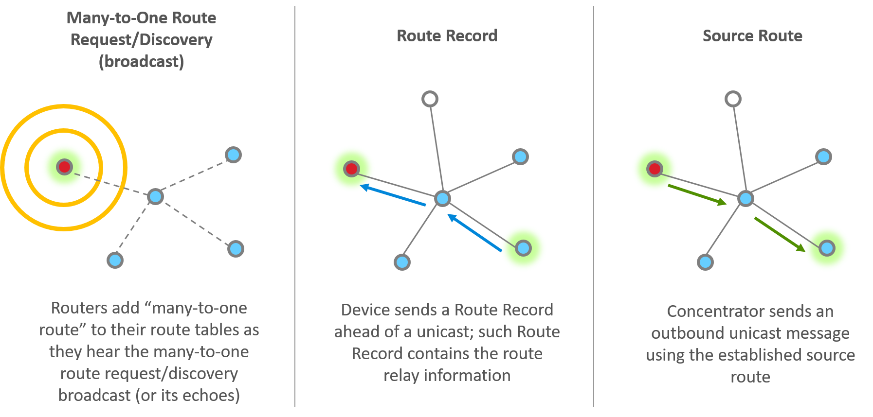
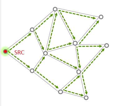
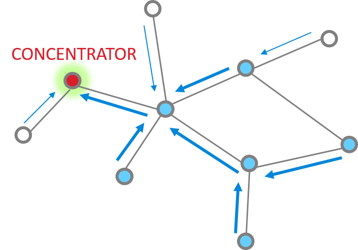
Many-to-one route request
The concentrator sends out many-to-one route request (MTORR) broadcasts periodically to all routers in the PAN. The MTORR broadcast has a “path cost” in its Command Frame, and this path cost is initially 0 when the concentrator transmits this broadcast. When a router relays a MTORR, it adds its link cost to the relayed broadcast, therefore the relayed MTORR broadcast carries the path cost between the concentrator and the relay node. If a router receives MTORR from multiple sources, it picks the path with the lowest path cost, and adds the corresponding router as its next hop to the route table in order to reach the concentrator. Note that the route table has entries for both traditional routing and many-to-one routing, and there is a flag to differentiate a many-to-one route.
When all routers have received the MTORR broadcasts, many-to-one routing is established, and all routers now have a route to the concentrator whether they need it immediately or not.
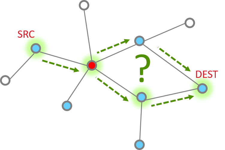
Route record
After a router has heard a many-to-one route request and established many-to-one routing, next time it sends a unicast (either on behalf of itself or any of its end device children) to the concentrator, it will use the many-to-one route. Moreover, a separate Route Record command will precede the unicast message to record the route the unicast message takes to reach the concentrator.
Source route
When the concentrator receives the unicast as well as the Route Record that goes with it, the concentrator reverses the relay list in the Route Record and stores that in its source route table. The concentrator can then use this source route when sending an outbound message.
A Closer Look at Source Routing#
To explain the construction of the source route better, let’s look at a particular route in the below example network and how the concentrator (with a node ID 0x0000) communicates with a remote node 0x1001.
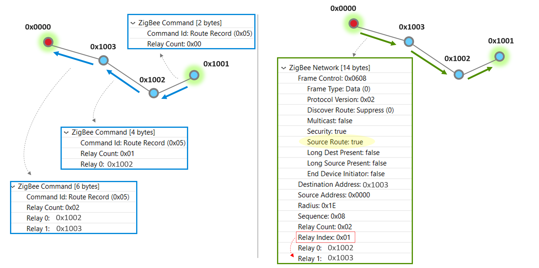
After the router 0x1001 has heard a many-to-one route request and established many-to-one routing, next time it sends a unicast to the concentrator, it will use the many-to-one route. Moreover, a separate Route Record command will precede the unicast message to record the route the unicast message takes to reach the concentrator. On each hop, look at the blue box which illustrates the Zigbee Command payload in the Route Record packet. When node 0x1002 relays the Route Record, it adds itself to the Route Record, and so does node 0x1003.
When the concentrator finally receives the Route Record from 0x1003, it stores the relay list in its source route table and knows that’s how it can reach 0x1001. Now look at the right half of this slide. Next time the concentrator needs to send a unicast message to 0x1001, it makes use of the source route. The green box illustrates the Zigbee Network header in the first hop of the unicast message, where the the relay list contains the entire route information from source to destination. and a Relay Index which indicates the immediate next relay point on this hop.
Note that the blue and green boxes are partial screen captures from a Network Analyzer trace. Please refer to our Network Analyzer training module if you are not already familiar with it.
Application Design Consideration#
While the many-to-one route requests, route record and source route are all supported at the Zigbee networking layer, you do need additional application layer support to manage the concentrator behavior; for example, when to send the next many-to-one route request. We provide this through the “Concentrator Support” Plugin.
There are two types of concentrator:
Low RAM concentrator
Only guaranteed to buffer most recent source route
Nodes send Route Record before every transmission to concentrator
OK if concentrator only talks to destinations in reply
High RAM concentrator
Assumes source route table is large enough for entire network
Route Record only sent initially (until first source-routed packet arrives from concentrator)
Reduced network traffic compared to the Low RAM option
How do you choose? Essentially it’s a tradeoff between RAM usage and network traffic. In the case of a High RAM concentrator, all source routes collected since the last MTORR are buffered, and therefore Route Record is only sent initially from a remote device; once a concentrator has successfully reached the remote device using the established source route, no more Route Record is sent from this remote device again until the next MTORR cycle. In comparison, on a Low RAM concentrator only the most recent source route is guaranteed to be buffered (which means reduced RAM usage), and remote nodes send Route Record with every unicast transmission to the concentrator (which means increased network traffic).
Other important concentrator configuration parameters to consider are:
Source route table size: choose according to the RAM resource and the network size.
MTORR interval: this is specified by a minimum interval and a maximum interval in seconds. If there is no route error or APS delivery failure, then the concentrator sends out MTORRs at the max interval.
Route Error Threshold and Delivery Failure Threshold: these are thresholds that trigger the next MTORR if the minimum interval has passed since the last MTORR.
In general, the smaller the MTORR interval and error thresholds, the faster and more responsive of many-to-one / source route establishment and repair, at the expense of increased network traffic. If the network is large and/or dense, frequent broadcasts and their echoes can quickly become overwhelming, so choose these parameters with care. If you are uncertain, you can always start with the default plugin parameters, then characterize the network performance and adjust from there.
Many-to-One / Source Routing vs. Traditional Routing#
Advantages#
In a network where there are frequent many-to-one messages toward one or few concentrators, Many-to-One and Source Routing have three major advantages over traditional routing. Let’s discuss them one by one.
Source routing reduces the demand for storing route table entries
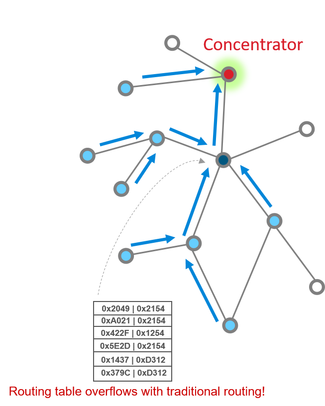
In the scenario where a large number of devices communicate with the concentrator, consider the route table on nodes close to the concentrator – with traditional routing, the route table on such a node would have to accommodate a large number of entries to provide routes to each device for which it is a relay point. Look at this picture as a simple illustration. The solid red circle represents a concentrator, while the dark and light blue circles represent routers, and white circles represent end devices. As you can see, with traditional routing, the router in dark blue would have to bear the burden of a large routing table since it is a relay point for many outbound messages. In large and/or dense networks, this means increased resource (RAM) demand for potentially many devices. With source routing, only the concentrator needs to store a large source route table.
Many-to-one routing is proactive
The routing is established during the many-to-one route request broadcasts, therefore each device will always have a route to the concentrator after the many-to-one route request broadcasts have reached every router via echoes. In comparison, traditional routing is reactive – routes are only established when a node tries to send a unicast message to another node for the first time and realizes that the routing information is missing.
Many-to-one and source routing together reduce broadcast traffic from one-to-one route discoveries
One-to-one route discoveries, used by traditional routing to establish or repair routes, are broadcasts each node needs to send in order to solicit route replies from the destination node. In comparison, in a network using many-to-one and source routing, a concentrator sends periodic many-to-one route requests to solicit many-to-one routes from all routers proactively. Reverse a many-to-one route, and you get the source route already. Many-to-one and source routing together is a much more efficient and responsible method to establish routing between a concentrator and outlying nodes compared to traditional routing in a large and/or dense network.
Limitations#
However, this does not mean many-to-one / source routing doesn’t have its own challenge or limitation.
While it’s most useful when most of the traffic involves many-to-one and/or one-to-many (which is true in a lot of networks, such as most HA networks), it does not address routing between non-concentrator nodes, for which we still need to rely on traditional routing. You may then wonder: can we have multiple concentrators? Well, the rule of thumb here is that we do not recommend having more than two concentrators in a network – the increased overhead and complexity would most likely bring more problems than help. In the vast majority of scenarios, there is one concentrator in a network.
Many-to-one / source routing could be less responsive to route changes compared to traditional routing in certain scenarios, especially when a network is initially forming and there isn’t any existing route yet. Note that during normal operation of the network, route changes should result in expected route error and/or delivery failure, which should trigger the next MTORR.
Table Routing#
EmberZNet Protocol Stack#
Below is the ZigBee system architecture from the Zigbee Introduction: Architecture Basics training module
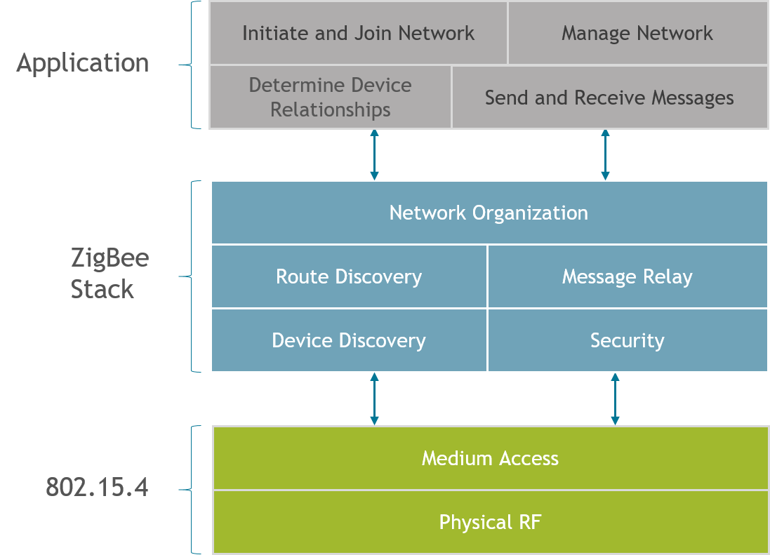
But we will focus on a specific function in the network layer of the protocol stack called routing. This behavior is defined by the Zigbee Alliance in the Zigbee PRO specification. Silicon Labs offers several Zigbee compliant platforms. For full platform details and up-to-date information, please visit zigbee.org.
Routing is the process in which a node relays information to another node that is either the final destination meant to receive this information, or a next step in the path leading to the final destination. In a mesh network, several routing mechanisms such as unicast, broadcast, or many-to-one routing / source routing are used to efficiently exchange data in the network.
As you may recall from the “Zigbee Introduction: Node Types, PAN IDs, Addresses” training module, routers and coordinators are expected to perform routing on a Zigbee network.
The main functions in the routing process include:
Route discovery, which is the ability to discover and record paths through the network, whereby messages can be efficiently routed
Relaying data using these paths to the next hop toward reaching a final destination on the route
Keeping track of and repairing broken routes, which is important to the dynamic nature of a mesh network
Participate in routing on behalf of end devices, etc.
Types of Routing#
How do you send a message from one node to another in Zigbee?
Routing will help you answer this question.
We have several types of routing commonly used in Zigbee:
Table routing or “traditional” routing is a method of routing where the source first discovers a route to the destination and stores it in a routing table. The nodes on the route then use the table to pass the message along, one hop at a time. We will look at this in greater detail in the coming slides.
Many-to-One / Source Routing: In many Zigbee networks, there is commonly one central node, a “concentrator”, which all nodes frequently communicate with. An example of such a node would be a gateway that collects status reports from all devices on the network. Many-to-one / Source routing scheme caters to these types of networks by creating an efficient means for nodes on a network to communicate with the concentrator. This topic is covered in a separate training module called Zigbee Networking Concepts: Many-to-One / Source routing.
Broadcast routing is a simplistic method of getting a message from the source to destination without having prior knowledge of how to reach the destination from the source. The source node sends the message to all nodes in its 1-hop-range and these nodes repeat the message to all nodes in their 1-hop-range until the message gets to all nodes in a specific radius.
Broadcast Routing#
In Broadcast routing, the source node sends the message to all nodes within a specific radius. A router within a 1-hop-range that hears the broadcast shall repeat it at least once and up to a maximum number of times until it hears the broadcast from all of its neighboring devices. Every time a broadcast message is repeated, the radius field is decremented and broadcast messages with a radius field set to 0 are not repeated anymore. Broadcast messages are jittered to reduce possibility of collision. There are mechanisms in place to prevent the same message from continuously looping around the network (a router can recognize a unique broadcast message and ensure that it is not repeated indefinitely).
The routers maintain the record of all the messages that they broadcast in a table called the broadcast transaction table (BTT).
BROADCAST ADDRESS | DESTINATION GROUP |
|---|---|
0xFFFF | All devices on PAN |
0xFFFD | All non-sleepy devices |
0xFFFC | All routing capable devices |
Network-level broadcast options exist to send messages to routers only, to all non-sleeping nodes including end devices, or also to send to sleeping end devices. End devices unicast their broadcast message to their parent node which in turn propagates the message through the network on their behalf.
While broadcast routing sounds simple, it can significantly increase the traffic in the network, cause congestion and degrade performance. It is for this reason that the Zigbee specification limits number of broadcasts in any given interval of time. They should be used sparingly and with careful consideration.
This is also not a reliable means of delivery to a sleepy end node because the parent device is responsible for buffering the message for the sleeping child but may drop the message before the end device wakes to receive it.
Table Routing: Route Discovery#
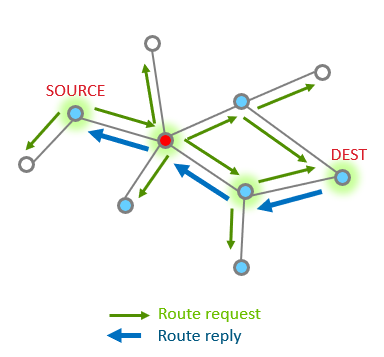
Table Routing is used when a node needs to send a message to a specific destination.
Route discovery is the first step in the table routing process and it happens when a node wants to send a message to a destination that it does not currently have a route to. Route discovery is performed automatically when EMBER_APS_OPTION_ENABLE_ROUTE_DISCOVERY option is set and no current route is available. Note that creating a route from node A to node B does not discover a return route from node B to node A. The return route discovery message will inherit EMBER_APS_OPTION_ENABLE_ROUTE_DISCOVERY from the incoming message to send the ACK.
Zigbee utilizes Ad-hoc On-Demand Distance Vector (AODV) routing to discover routes in the mesh network and to route packets. The links with the lowest cost will be chosen. The cost of a link is based on various factors (Link Quality, Probability of packet delivery on link, etc).
Each node stores information about next hop to a specific destination. If the next hop is not known, route discovery must take place in order to find a path. Since only a fixed number of routes can be saved on a node, route discovery may take place more often in a network with a large number of nodes where there is frequent communication between many different nodes.
When a source node needs to discover a route to a destination node, it sends a broadcast Route Request command. The Route Request contains the source address, destination address and path cost (to measure route quality and choose best route). Intermediate nodes listen to and rebroadcast this request while updating the path cost field and propagate the message through the network. They also store the route entry into the route discovery table.
Table routing : Link Cost#
If there is more than one viable path to get from one node to another, how do I know which is better?
Often times, in a mesh network, there are many possible routes to get from one node to another. Link cost is a metric that applies to a pair of nodes that tells us how well the two nodes can hear each other. When the route between 2 nodes is composed of multiple links, the path cost is the sum of the individual link costs on the path. During routing, link and path costs are used to come up with a route that has the best possibility of successful message reception.
Routers keep track of link status in a Zigbee network, and hold the link costs in their neighbor table. Routers can determine incoming link quality from the physical layer using the link quality measurements. They exchange this information using Link Status messages that are 1 hop broadcasts (no retries) with other routers to get the outgoing link quality.
Upon receipt of a Route Request command frame, the neighbor table is searched for an entry corresponding to the transmitting device. If no such entry is found, or if the outgoing cost field of the entry has a value of 0, the frame is discarded and Route Request processing is terminated. If an entry is found with non-zero outgoing cost, the maximum of the incoming and outgoing costs is used for the purposes of the path cost calculation, instead of only the incoming cost. This value is also used to increment the path cost field of the Route Request frame prior to retransmission.
Outgoing and incoming links might not necessarily be the same due to differences in local noise floor, differences in receiver sensitivity, etc. The EmberZNet stack tends to prefer a link with a symmetric link cost over one that is not.
In addition to link quality, neighbor tables also store the age of the link. Generally speaking, the age of the link indicates the amount of time that has elapsed since hearing from the neighbor. The age field is updated when a new link status message is received from the neighbor. Links are marked stale after a period of inactivity.
Table routing : Route Repair#
What happens when one or more nodes on a previously discovered route go out of commission?
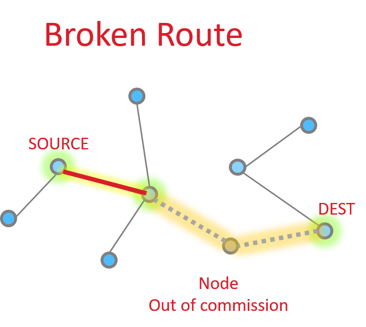
The source node is able to request an application level acknowledgement (APS ACK) from the destination. The sending device will be informed when the message is successfully delivered. If it does not receive this acknowledgment, it can then take steps to repair the route.
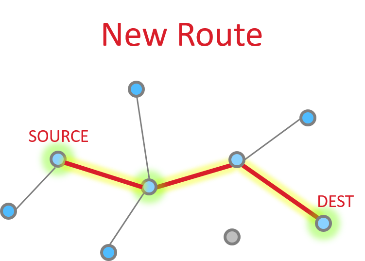
Route repair follows exactly the same steps as route discovery, but the damaged node does not participate, resulting in a different route choice. The routing tables are updated to reflect the new next hops, and the message is successfully delivered along the new path as shown in the picture on the right.
If no alternative path is available, the sender is informed that the message could not be delivered. In EmberZNet stack, this is denoted by a response with EmberStatus of EMBER_DELIVERY_FAILED (0x66). EmberZNet will attempt to deliver a message again before performing the route repair. Route repair is performed automatically when EMBER_APS_OPTION_RETRY and EMBER_APS_OPTION_ENABLE_ROUTE_DISCOVERY are both set in the message options.
For other EmberStatus’, refer to error-def.h. For more APS options, refer to ember-types.h
Unicast Message Delivery#
One hop#
So let’s look at the basic message between two nodes, since this is most simple. This is the building block from which all other messaging is done.
When it works perfectly, single hop message delivery is a two part process with 4 steps total. Within 802.15.4 there are MAC acks for point to point jumps. Zigbee applies Application level acknowledgments to ensure end to end delivery.
So we start out with a message being sent Message Sent

This message then is acknowledged at the MAC layer

Since the message has been sent all the way to it’s destination, and it is requested, we must now get the application ACK. So this is now sent by the destination.

Since this is another 15.4 message, there has to be a point to point acknowledgement

And that is the whole process.
Multiple hop#
More nodes end up with more steps, but as a whole the process is the same, just longer. Instead the message traverses along being MAC ack’d until it reaches its destination and then an APS ack returns down the same route with each hop being MAC Ack’d.
The message is sent

The point to point MAC Ack is received
Since our message has not made the final destination, it continues Next hop of the message and the MAC ACK
|
|


And one more hope to get to the destination
So then our App layer must send an acknowledgement. This is just like the message
|
|
The APS ACK is send backwards, with each step being MAC ACK’d
What happens if a message has a failure along part of this route? The EmberZNet stack has retry mechanisms in place to help resolve issues and ensure delivery. The MAC retries are 802.15.4 mechanisms that ensure delivery from point to point. If a MAC ack is not received, the MAC layer will automatically try sending the packet again. Failure at this level is around 40mSec EmberZNet further adds NWK layer retries. It is a timer up to 500mSec that retries MAC layer messages (point to point). These happen should the MAC retries fail. Finally there are APS retries, these are application layer acknowledgements which are designed to ensure messages are delivered end to end. Should an APS retry not be received, then the application will attempt to transmit a message again, following the steps above as before.
The APS retry is a optional feature which can be configured by APS options EMBER_APS_OPTION_RETRY. We will discuss more APS option in the later.
ZDO (Network and device and Service Discovery Manager)#
Zigbee Device Object#
The ZDO is a group of messages, concepts, and primitives that are all device specific, this way another device can get to know another device on the network. A good example is an end device that is requesting the network Key from the coordinator or the coordinator wants to get more information about the number of endpoints on a device. All these actions we collect in the ZDO group, we can distinguish the following categories in this group:
Network Manager: Handles network activities such as network discovery, leaving/joining a network, resetting a network connection and creating a network.
Device and Service Discovery: Handles device and service discovery, so other devices in the network can get to know the device capabilities.
Binding Manager: Handles end device binding, binding and unbinding activities. This is used to make binding between 2 endpoints on separate devices. This way we can bind a switch to a dedicated light. This will be handled in Binding.
Security Manager: Handles security services such as key loading, key establishment, key transport, and authentication. This will be handled in more detail in Zigbee 3.0 Security.
Depending on the device not all of these subcategories are mandatory. We will dive a little deeper in the device and service manager and the network manager. The binding manager and the security manager will be discussed separately.
Name | Status |
|---|---|
Network Manager | Mandatory |
Device and Service Discovery | Mandatory |
Biding Manager | Optional |
Security Manager | Optional |
Network Manager#
Main Functions:
Facilitates the scan procedure (Scan all channels for network creation or to find a joinable network)
Supports orphan and rejoining the network
Detects and reports interference to support channel changing
One of the tasks for the Network Manager is to form or join a network, before forming a network it will scan the channels to asses which channel is the best to create a network. The best channel is the channel with the least interference, this can come from other Zigbee networks on the channel but can also be from other network types in the 2.4 GHz band, think here about Bluetooth or WIFI. First, it will scan the predefined channels and after that, it will scan all the channels to find a quiet channel. This has a downside that a joining device can’t know up front where to find the network, It will use the same principle as the with the network creation to find a joinable network. It needs also to do a scan to find the network could be joined. For the joining (association) procedure we advise to use install code based association, this is a key based joining procedure.
Another task of the network manager is to manage the orphan and rejoining process. If a device is losing communication with the network, which can be caused for example by a power loss. If they still have the correct network key the device is able to join the network again with a rejoin request. This is the same procedure as the association procedure only without the association broadcast. Also for rejoining counts that the network may be on a different channel, here we do the same scan procedure again.
When an end device is losing communication with the network, it will try to find the parent with an orphan scan. This scan will search for the parent on different channels. If a rejoin or an orphan scan is not successful the device shall try to join the network through the association process.
Also, the task of the network manager is to report the interference on the channel. If there is too much interference on a channel the device will notify the coordinator. Which may decide to move the channel to another one where there is less interference. The interference measurement when the network is created is just a spot check, so it will not guarantee future interference. The algorithm to decide if the coordinator is switching channels is up to the user. Before switching channels the coordinator is broadcasting a network update request, so the whole network knows we move to another channel. If one of the device for some reason doesn’t hear the broadcast it will do a channel scan and rejoin the network.
All the functionality of the network manager is provided by the plugins in the stack.
Component |
|---|
Network Steering |
Network Creator |
ZigBee Pro Stack |
ZigBee Pro Leaf Stack |
The Network Steering Component allows you to join a network, this will also provide the network scan.
The Network Creator allows you to create a network this is mostly used for coordinators.
The ZigBee Pro Stack will provide the base stack for Zigbee
The ZigBee Pro Leaf Stack will provide the base stack for Zigbee end devices.
Device and Service Discovery#
Main Functions:
Device Discovery:
IEEE Request: zdoIeeeAddressRequestCommand
Network address Request: zdoNwkAddressRequestCommandService Discovery
Node or power descriptor: emberNodeDescriptorRequest
Active endpoints of a device: emberActiveEndpointsRequest
Simple descriptor: emberSimpleDescriptorRequest
Match descriptor: matchDescriptorsRequestRouters and coordinators can store information & messages for sleepy end devices
After joining a network we don’t know anything about the device or his service. Whith the device discovery you can obtain:
The IEEE address is the unique EUI64 address
The network address of the device is the 16 bits short address of the device
This gives other devices in the network the opportunity to discover the EUI64 of a device whit the corresponding short address or the other way around.
With the service discovery, other devices in the network can obtain the services that the device is providing, it is nice to know if a device is a light or a motion detector. We can request the power description of the device, this will return the power mode of the device, sleepy or not sleepy, available power sources and the current power source and his level.
We can request the active endpoints of the device, with this information we can ask a simple descriptor of the endpoints. This will give the device id, profile id and the clusters that are available on that particular endpoint. Whit this information you can paint a good picture of what the endpoint is capable of, also this information is used to form a binding to an endpoint.
Routers and coordinators can have the ability to store messages and information about a sleepy end device. This is to minimize the messages towards the sleepy end device, this extent the battery life of the device. The stack stores the short id and the EUI64 of the sleepy end device, to reduce messages. Also, parents have the ability to store complete messages for the sleepy end device, this way when the sleepy end device is waking up it can read the message and reply on it if needed.
Zigbee 3.0 Security#
The need for Security with Zigbee#
So why is there such a big need for Zigbee Security?
When you are just talking about a few light bulbs, is security that big of a deal? They can flash some lights, but is that really a big issue? Pranks, sure, but beyond that it doesn’t seem that big of a deal.
How about when you have a Zigbee enabled thermostat? A little larger target (heating-cooling-air handler), but again, really just a prank level target.
But what about Smart Energy? Now we are talking about the potential of introducing some issues with power and gas delivery. Potentially costing you a lot of money.
If you have smart shades, you give people the means of opening your shades. This could be a minor inconvenience to potentially letting burglars know you are not home.
What about devices that give Zigbee Home Automation access? You start tying these all together. Now any or all of these become issues.
And finally we have Zigbee locks and devices that can be used to give people direct access to your home. Now all of a sudden we are talking about a major security issue, because compromising your Zigbee network potentially compromises your home’s security.
So as you see as Zigbee becomes a bigger piece of the smart home, security can’t just be an afterthought in designs, but needs to be a major consideration to help protect not just networks but our customers as well.
Zigbee Network Security#
One of the first things we should look at within Zigbee is network security. Zigbee operates under the open trust model. This means that all devices that are joined to the network are “trusted” and data between them can be encrypted. Within the Zigbee spec, all traffic is encrypted. Zigbee utilizes AES-128 for the encryption.
AES-128 is the 128 bit variant of the Advanced Encryption Standard, it is based on the Rijndael (PRONOUNCED - Rhine Dahl) block cypher. Rijndael is a symmetric key algorithm, this means that there is only 1 key for both encryption and decryption. Rijndael allows for variable block size (the base element of the data to be encrypted) or key size, so long as they are multiples of 32. AES uses a subset of Rijndael which has a fixed block length of 128 bits (16 bytes) and variable key sizes of 128 (used here, hence AES-128), 192 or 256 bits. AES is an extremely strong encryption standard and as of now considered uncrackable (current computing would take billions of years to brute force).
The key for decoding network traffic is called the Network Key. It is a 128 bit value which. When your network is first created, the network key is chosen, at random, by the device creating the network, the coordinator. This network key can be changed by the coordinator and then must be distributed to all devices on the network before nodes switch to the new network key. Zigbee additionally has some mechanisms in place in which the key should be changed.
Zigbee Packet Format#
A Zigbee packet is basically a modified 802.15.4 packet. And 802.15.4 packet has a header and payload section.
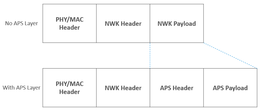
Zigbee takes the 15.4 payload and uses it for a Zigbee header and payload or data.
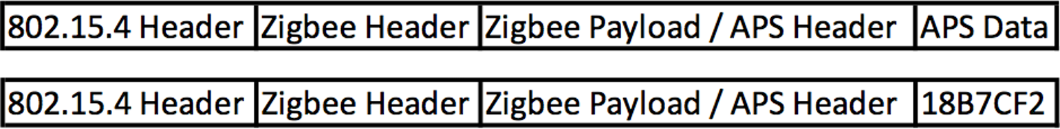
If you have additional Application Support Sublayer (APS) data, then the APS header and payload are stored as part of the Zigbee payload.
Packet Encryption#
So simplifying our Zigbee packet down to just the 802.15.4 header, Zigbee header and payload, we can see how encryption of a Zigbee packet works.
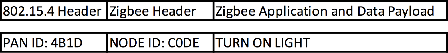
So here we have a packet, which is for PAN ID 4B1D (four-B-one-D), heading to node C0DE (C-zero-D-E), with the command TURN ON LIGHT. But since this is a Zigbee packet and encrypted over the air (OTA) this packet will look like this
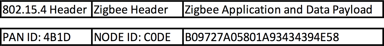
The PAN ID is visible because the network needs to quickly know if the packet is meant for it’s network, without trying to decode the packet. The same is for node data so that nodes can quickly relay packets along the network without decoding them. But the payload is encrypted, when it reaches its destination, then the packet is decoded.
If you send the same command every time, you are susceptible to replay attacks. Zigbee makes use of Frame counters to defeat replay attacks. The Frame counter is incremented each command you send. As nodes receive messages from different nodes, the frame counter is recorded. If subsequent message from the node do not have a higher frame counter than the previous message, the message is ignored.
Other Network Security Considerations#
As noted there is a single network key. This under open trust, any device has the ability to see all traffic on the network. This means that:
It’s important to keep rogue devices off the network, and certainly try to only admit trusted devices to join the network. Make use of other security (APS Security) can be used for additional encryption Protect the joining process – as we saw in our example, if devices get the network key when they join, you can spot the network key, if you know where and how to look for the key.
APS Security#
Application Layer (APS) Security is used as additional encryption between nodes. It is used to protect data from the rest of the network.
Using link keys, traffic between nodes can be additional encrypted, using similar techniques as network layer encryption, but in this case primarily on APS payload data.
Just like Network encryption, this is an additional layer of AES-128 security. And in the case of Link keys, every device starts with a pre-chosen one and they can be changed at any time.
What are the uses for APS Encryption?
Securing data from point to point. While some of the message can be decoded by other nodes, the APS payload cannot. This means your data is secure along your whole route.
Within Smart Energy, this is the standard message sending method.
This is compatible with older Zigbee Pro and current Zigbee 3.0. EmberZNet allows for different layers of encryption. All traffic can be APS encrypted or it can be done on a packet by packet basis, choosing only some packets to be APS encrypted.
Dynamic Link Key#
A new feature introduced in Revision 23 is Dynamic Link Key (DLK) joining which uses elliptic curve Diffie-Hellman key negotiation to establish keys and authenticate devices before joining the network as well as adding the Network Commissioning with High Security Join Feature. This ensures that the trust center can hold onto the network key for as long as possible before sharing it with the new device.
If both Trust Center and joining device support Dynamic Link Key (DLK) exchange, a new link key can be securely established before the device is fully joined on the network and sent the Network Key. At minimum this provides protection against passive attacks, listening for network keys sent with known keys, since key values are generated during commissioning and are unique to each negotiation session.
However, after DLK exchange is completed, the Trust Center may choose to delay sending the network key and 'interview' the device by sending sending arbitrary data requests downstream to the joining device, to determine more about its capabilities and characteristics before deciding whether to authorize it.
Tag-Length-Value#
R23 introduces a new pattern for frame formats with extensible payloads. Some messages may come with 0 or more data elements encoded in Tag-Length-Value (TLV) format. The three parts of a TLV are: Tag, which identifies uniquely the type of data; Length, which specifies the length of the value in bytes; and Value, which contains the data representing the value for the type. TLVs are used as a way to encode payload data in a future-compatible format that lets stacks parse what they know and silently pass on unfamiliar data. This means that Zigbee payloads are far more flexible and dynamic.
Multi-Hop commissioning & APS Relay Commands#
R23 has introduced APS Relay frames which provide a secure mechanism to enable Multi-hop commissioning. An unauthenticated device sends a network commissioning request to a router in the network which sends an Update Device command to the Trust Center (TC) with TLVs (Tag Length Values). The TC then begins Key Negotiation by sending APS layer messages to the unauthenticated device relaying traffic via the router. The relayed packet payload includes the APS header and is contained in the TLV. The final hop from the router to the joining device does not have network security as it has not yet joined the network. The relay frames will work regardless of the number of hops and in the case of a single-hop the TC assumes the role of the relay router. Additionally, the relay frame APS sequence number is separate from relayed packet. DLKs established during Key Negotiation ensure that these messages are secure without revealing the Network Key before the new device has officially joined the network.
More information on Revision 23 can be found here.
Joining and Rejoining Process#
Joining process#
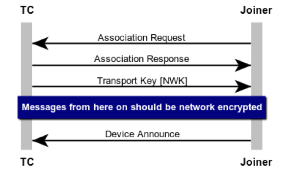
A device joining a Zigbee network is a basic 3 step process:
The Association – This is the process of a node requesting access to the network and the network responding with a decision to join or not. In most cases this will be YES.
Transport Key – This is the step when a device is sent the current network key
Device Announce – This is when the device broadcasts to the network that it has joined and ready to operate. At this time other nodes will see the message and can start inquiring about functionality and the like.
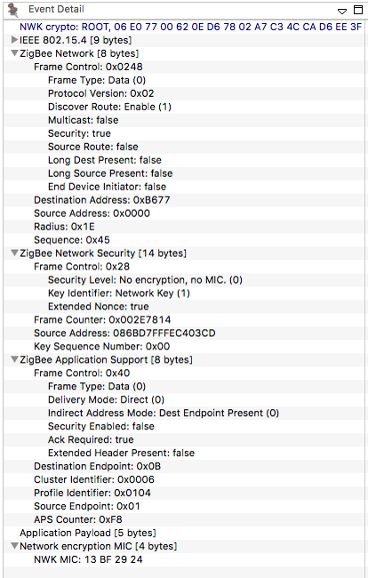
Because as you can see below – in your key transport packet, the Network key is visible (see the line 5 from the bottom - that Is the network key).
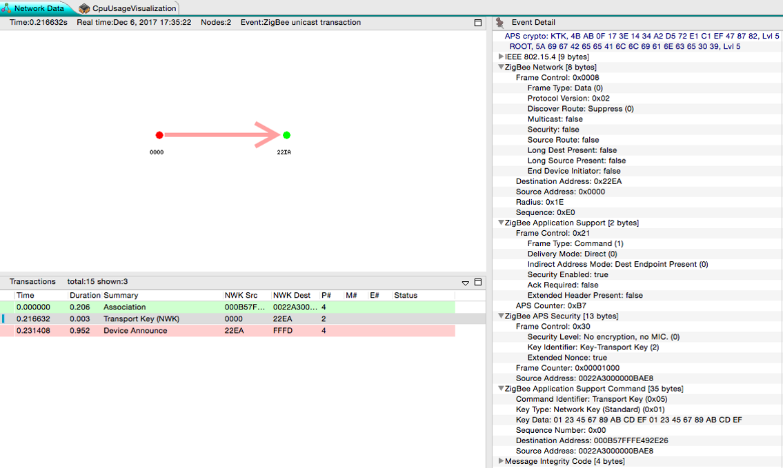
Now we will throw some security on this. Because this is potentially visible to the world, this packet is encrypted using APS security, which is noted on the top of the event details box. Now under older Zigbee Pro/HA security, this utilized a well known link key “ZigbeeAlliance09”. This key was part of the Zigbee spec, so it was easy for all to read. And while it was understood that publishing this key made it vulnerable, it was also seen as momentary and not deterministic. So while a sniffer could see the key if they got this packet, this packet was just 1 out of so many packets. Plus it was not easy to know when a join process was taking place.
Rejoining process#
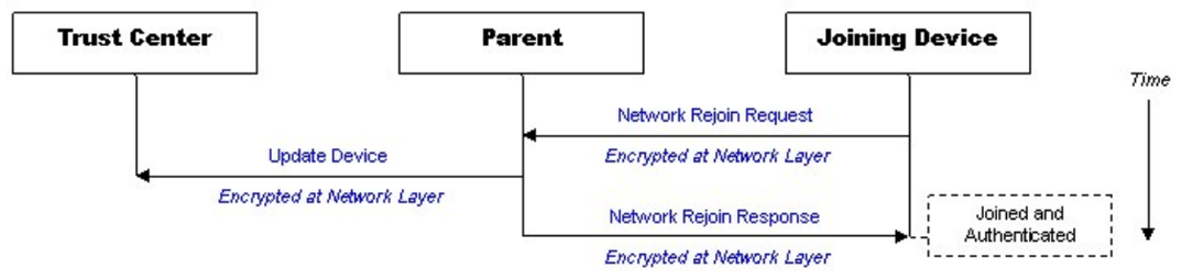
Because of the end device – parent relationship, end devices occasionally need to rejoin their networks. Rejoining is the process in which a device which has all of the network information, but somehow loses contact with the network, gets back on the network. This is just for end devices which must maintain some link with the network and their parent to remain in device tables.
The first type of rejoin is a Secure Rejoin. In this step a device uses a network encrypted message to request to be readmitted to the network. If the nodes parent doesn’t have an issues with this (IE, the device still remains in it’s child table), then it will send a message to the trust center that a device is alive and it will let the node back into the network. In this case the whole process is encrypted.
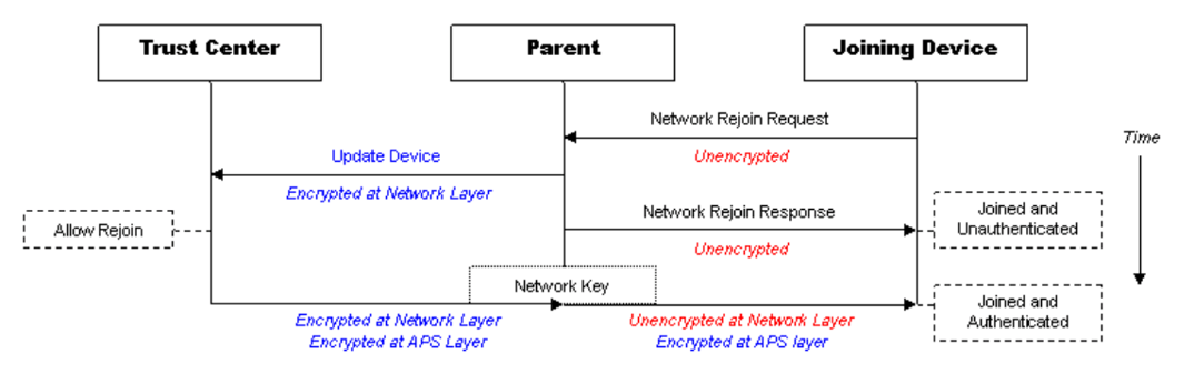
Secure Rejoins only happen for a set duration or number of failures. But as they fail enough or should a parent have forgotten about a device (it ages out of it’s child table), then an end device will roll back to a Trust Center Rejoin. In this case it will send an unencrypted rejoin request, the response to this will also be unencrypted. The device will also be send the network key, just in case, encrypted with the devices link key. In Zigbee Pro/HA this was again just the well known link key.
Joining/Rejoining Security#
Joining was always seen as the weakest link in joining devices to the network. Now let’s take a history lesson along from Zigbee Pro to the discovered Vulnerabilities and how Zigbee 3.0 came to be.
Zigbee HA 1.2
Zigbee utilized a single link key for most processes
ZigbeeAlliance09
5A 69 67 42 65 65 41 6C 6C 69 61 6E 63 65 30 39
Key was published as part of the Zigbee specification
Other link keys were allowed, but rarely used
The use of the default key was seen as a risk, as sniffing the network key transfer packet would reveal the network key. But this risk was seen as minor as joining or rejoining processes were not predictable and the window of joining was so small.
That was until Black Hat 2015, where Cognosec Gmbh presented an exploit in which they were able use some tools to gain access to a Zigbee network in a very deterministic way. They called their presentation The Good, the Bad, and The Ugly.
Zigbee Unsecure rejoin outlined at the Black Hat USA 2015#
Discovered by Cognosec security engineers Tobias Zillner and Sebastian Strobl
Process:
Hacker has a jammer and a sniffer
ZED is jammed long enough that it loses connection with parent network and attempts a secure network rejoin and the process fails.
Once the secure rejoins fail the ZED attempt to join using the Zigbee default key – thus exposing the network key to the sniffer
Hacker could then read all network traffic
Hacker could do a secure rejoin and get a rogue device onto the network
Zigbee 3.0#
This caused Zigbee 3.0 to be created. The basic idea was to do everything to get customers away from the well known link key.
They would leave a caveat for using ZigbeeAlliance09, but as a whole you wanted to use a new link key. Ideally customers would move to unique codes that was just for joining.
Along with this, changing link keys became mandatory on devices. When a Zigbee 3.0 device joined a network, it would check that the network had the facility to issue new link keys and if so, request a new one.
Finally a new idea was introduced, that of a single use joining install code. This was a code which could be derived from a some other value, these keys would be unique for joining and then changed out. They would be shared with the network in some out of band way, just as a computer, mobile device or web interface. The idea was that with these single use derived codes the joining process became much more secure.
Looking at the below picture, you see the 3 old joining steps: Associating, Transport of the network Key and the device announce.
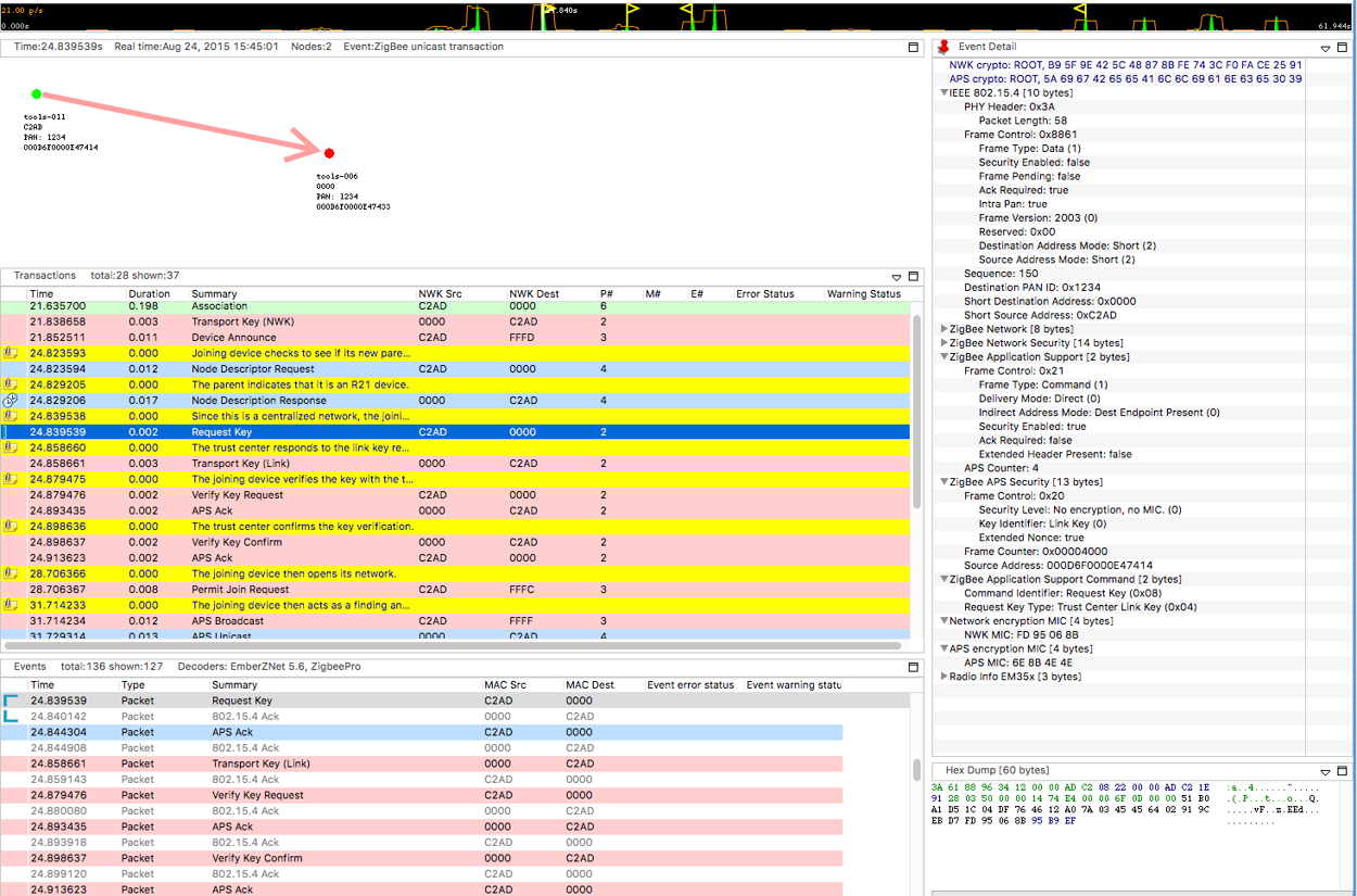
But now after that you have a few more necessary steps.
First after the Device Announce comes a standard Node Descriptor Request. This happened before under Zigbee Pro, but now the Node Descriptor Response has a new field – Stack Compliance Revision. If this value is R21 or greater (the revision of the Zigbee Spec in which Zigbee 3.0 was introduced), then a joining device knows it’s joining a new Zigbee 3.0 network and the new joining process will continue
Request Key – Once R21 compliance is determined, the the joining device will request a new link key from the trust center.
Transport Key (Link) - The trust center will generate a new link key and sends it to the joining device.
Verify Key Request – Using the old link key, the node will request that the network verify the new link key
Verify Key Confirm – Here the trust center will use the new link key to send a message to the joining node. If this message is ACKed, then the Link Key is considered updated and the joining process is complete.
Taking a closer look a different types of keys and their support within EmberZNet, we have the following.
First, you see that a trust center needs to support at a minimum two keys: the well-known key for backwards compatibility and a slot to hold install code derived keys.
Since there is a key table and keys must be saved across reboots and the like, the key table must be stored in non-volatile memory, this is tokens in EmberZNet.
There is also a transient key table for keys which have a temporary life span. Any key which is placed in the transient key table will time out at some time in the future.
To conserve memory, EmberZnet utilizes a feature called hashed link keys which are keys hashed from the EUI64 of the other node and a secret key which only the Trust Center knows. This is beneficial all around as it utilizes no memory or token space and the impact on computations is minimal.
At the bottom here we show how the Gateway or other joining device within the EmberZnet stack utilize the preconfigured key slots within their own memory when they update their own link key table.
Below is the key table from a gateway. Note the Network key (line 4), The TC Link Key and the Link Key table (lines 8, 11 and 12). As well as the transient key table. It also notes packet buffer usage of the transient key table.
Gateway>keys print
EMBER_SECURITY_LEVEL: 05
NWK Key out FC: 0000000B
NWK Key seq num: 0x00
NWK Key: 4B F8 EB DF C1 92 09 3C 5A D9 FD C7 77 36 B3 9F
Link Key out FC: 00000000
TC Link Key
Index IEEE Address In FC Type Auth Key
- (>)0800000000000000 00000000 L y 46 F8 4B 89 13 F2 FC 6E D8 4F B0 94 50 DA 6D DF
Link Key Table
Index IEEE Address In FC Type Auth Key
0 (>)001F023DCB5A7F22 00000000 L y 74 68 69 73 20 69 73 20 73 69 78 74 65 65 6E 20
1 (>)6569676874793830 00000000 L y 6F 6E 65 74 77 6F 74 68 72 65 65 66 6F 75 72 66
2/4 entries used.
Transient Key Table
Index IEEE Address In FC TTL(s) Flag Key
0 (>)0600000000000000 00000000 0x00B4 0x0000 5A 69 67 42 65 65 41 6C 6C 69 61 6E 63 65 30 39
1 entry consuming 1 packet buffer.
Below is the key table of a non-coordinator device. Note it only has it’s own Link key as well as the network key.
Joiner>keys print
EMBER_SECURITY_LEVEL: 05
NWK Key out FC: 00003014
NWK Key seq num: 0x00
NWK Key: 4B F8 EB DF C1 92 09 3C 5A D9 FD C7 77 36 B3 9F
Link Key out FC: 00003002
TC Link Key
Index IEEE Address In FC Type Auth Key
- (>)0800000000000000 00000005 L y 83 A3 6E 78 23 D7 A0 85 9D B2 0F 80 15 0D 88 F6
Link Key Table
Index IEEE Address In FC Type Auth Key
0/0 entries used.
Transient Key Table
Index IEEE Address In FC TTL(s) Flag Key
0 entry consuming 0 packet buffer.Summarizing, there are three places a link key is stored on a device
Preconfigured key slot – persisted (token)
Transient key table – RAM
Key Table – persisted (token)
Furthermore, since the stack is well versed in these key values, there is a well defined state machine within the stack which determines the order in which encrypting and decrypting take place and with what key.
Additional Security Considerations#
Most of the security topics we have discussed had to do with security considerations within EmberZNet and primarily with network security. But there are other issues which reside outside the stack. This is some details on an “IoT worm” which was created by some researchers in Israel and Canada. They were able to exploit two bugs within Phillips bulbs which allowed them to spread a virus across Phillips Hue bulbs.
First they exploited a bug in Atmel’s ZLL implementation they were able to touchlink to a bulb from hundreds of meters away (a process that generally needs to be within a few centimeters). Doing so, they could “steal” the light bulbs from it’s network to their own network. Then they further exploited the fact that Phillips didn’t require signed bootload images to install their own hacked firmware within the lights. This allowed them to spread a self propogating worm.
This demonstrates not just the need for companies like Phillips to consider security as they make their devices, but also vendors, like even Silicon Labs, to make sure they properly test their stacks and don’t have bugs like this in their code.
ZigDiggity#
Out on the internet right now you can download a utility called ZigDiggity by BishopFox. They call it a hacking toolkit. The primary feature of ZigDiggity is to steal Zigbee devices from networks. Utilizing a beacon storm, ZigDiggity is able to then use this in conjunction with an ACK attack to cause devices to jump from their own network to the network of ZigDiggity. So clearly there are tools out there which you must be careful about.
BishopFox: https://www.bishopfox.com
ZigDiggity on github: https://github.com/BishopFox/zigdiggity
And this brings us to the internet as a whole. There are a ton of resource out there on the internet from hackers and hobbyists. These people are seeing what they can do to exploit security and Zigbee.
Silicon Labs and their customers need to be aware that these people are watching and are ready to exploit any bug which they discover. So we need to make sure there are as few for them to find.
IOT is going to be here to stay. And unless the creators work to protect everyone, they are going to leave major exploits for all to use.