Application Layer#
Finding and Binding#
Overview of Finding and Binding#
As we know, a switch always binds to a light in a Zigbee network. Is there any easy way to implement it? The answer is yes, finding and binding can be used here.
Finding and Binding is a cluster commissioning method to establish application connection automatically, which can be invoked by user interaction on two or more endpoints on two or more nodes. This method identifies and discovers endpoints using the Identify cluster. For each match between corresponding application clusters on the endpoints, binding is created at the initiator of the application transaction.
For example, both the switch and light have an On/Off cluster. The binding for the On/Off cluster will be created after the finding and binding operations are completed on both sides.
Which device needs perform Finding and Binding#
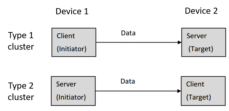
There are two kinds of clusters: Type 1 and Type 2. An application cluster is either a Type 1 or Type 2 cluster, depending on its primary functional transactions. A transaction has an initiator and a target.
A Type 1 cluster’s primary function is to initiate transactions from the client to the server. For example: An On/Off client sends commands (data) to the On/Off server.
A Type 2 cluster’s primary function is to initiate transactions from the server to the client. For example: A Temperature Measurement server reports to the Temperature Measurement client.
For a Type 1 client or a Type 2 server cluster, the application shall perform finding and binding as an initiator endpoint.
For a Type 1 server or a Type 2 client cluster, the application shall perform finding and binding as a target endpoint.
In summary:
The application SHALL perform finding and binding as an initiator endpoint
Type 1 client cluster
Type 2 server cluster
The application SHALL perform finding and binding as a target endpoint
Type 1 server cluster
Type 2 client cluster
Finding and Binding procedure#
For a target endpoint#
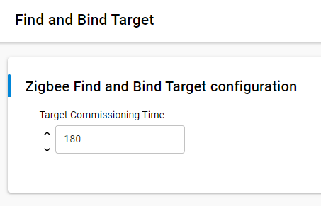
On the finding and binding target endpoint, once the finding and binding target start, it will write the Time attribute of the Identify cluster to make sure the target can be identified. In Software Components, the Time attribute can be configured in “Find and Bind Target” component and the default value is 180 seconds. During the identify time, the target should respond to the Identify Query from the initiator. Once the decrementing Identify's Time attribute reaches zero, the target shall terminate the finding and binding procedure.
It means that the finding and binding target should write the Time attribute of the Identify cluster to make sure it can be identified during the finding and binding procedure.
In Software Components, the Identify Time can be configured in “Find and Bind Target” component and the default value is 180 seconds.
For an initiator endpoint#
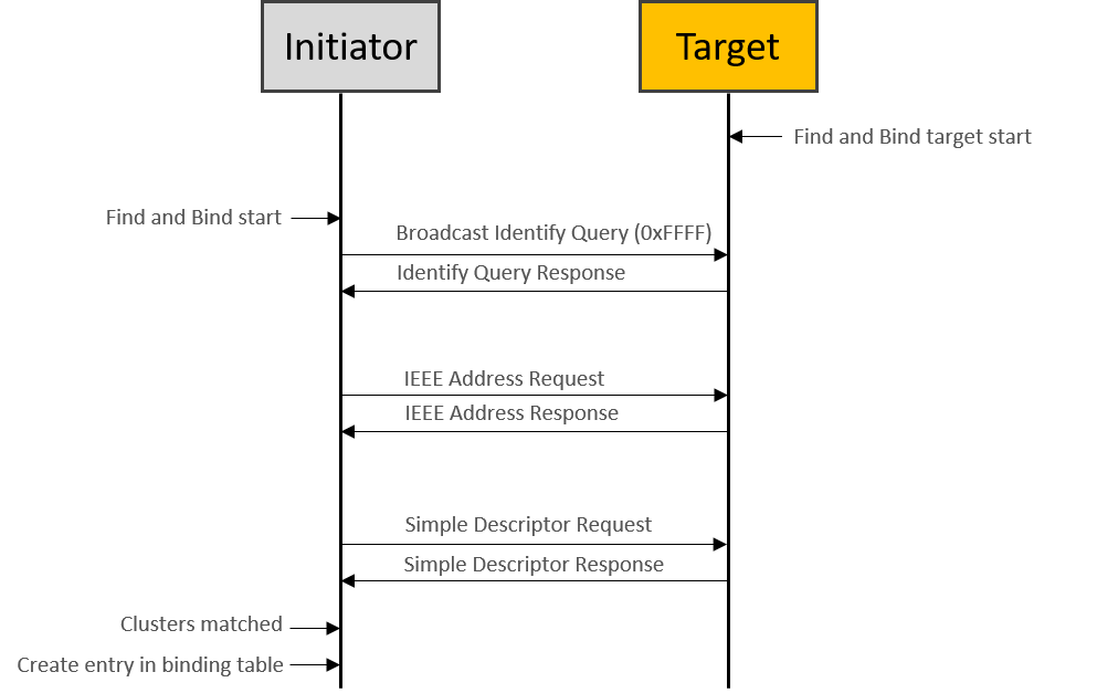
On the finding and binding initiator endpoint, it broadcasts Identify Query to all nodes which include sleepy end device (using the broadcast address 0xffff). If no Identify Query, Identify Query Response commands received, the initiator sets status to NO_IDENTIFY_QUERY_RESPONSE and terminates the finding and binding procedure.
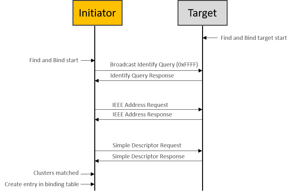
If at least one Identify Query Response is received, the initiator sends IEEE address request to get the EUI64 of the target, which will be used for binding table entry later. And then the initiator sends Simple Descriptor Request to get the clusters info on target. Once some clusters matched between initiator and target endpoints, then the binding is created for every matched clusters on initiator. If a group binding is requested, the initiator endpoint configures group membership of the target endpoint, which means that the initiator unicasts “Add Group” command to the target.
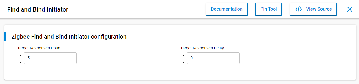
In Software Components, there are two options that can be configured in the “Find and Bind Initiator” component. The “Target Responses Count” means the number of the target responses that the initiator will accept. The “Target Responses Delay” means how long the initiator will listen for target responses. You can feel free to configure these options to fit your user case.
The APIs to start finding and binding operations#
The API to start target finding and binding operations is emberAfPluginFindAndBindTargetStart(), which can be found in find-and-bind-target.h. It is a call to this function will commence the target finding and binding operations. Specifically, the target will attempt to start identifying the endpoint that is passed as a parameter. The EmberAfStatus value describing the success of the commencement of the target operations.
As the similar, the API to start initiator finding and binding operations is emberAfPluginFindAndBindInitiatorStart(), which can be found in find-and-bind-initiator.h. It is a call to this function will commence the initiator finding and binding operations. Specifically, the initiator will attempt to start searching for potential bindings that can be made with identifying targets. The EmberStatus value describing the success of the commencement of the initiator operations.
Please note that the target should be started first during the finding and binding procedure.
Testing on Z3Light and Z3Switch sample#
It is easy to set up the testing for finding and binding with Z3Light and Z3Switch samples.
First you can build the two samples directly, download the firmware to the kits separately, and then join to the same Zigbee 3.0 network formed by a Z3Gateway.
On the Z3Light side, launch the console and type CLI command plugin find-and-bind target 1.
Z3Light>plugin find-and-bind target 1
Find and Bind Target: Start target: 0x00
T00000000:RX len 3, ep FF, clus 0x0003 (Identify) FC 01 seq 00 cmd 01 payload[]
T00000000:RX len 5, ep 01, clus 0x0003 (Identify) FC 00 seq 00 cmd 0B payload[00 00]On the Z3Switch side, launch the console and type CLI command plugin find-and-bind initiator 1.
Z3Switch>plugin find-and-bind initiator 1
Processing message: len=3 profile=0104 cluster=0003
T00000000:RX len 3, ep FF, clus 0x0003 (Identify) FC 01 seq 00 cmd 01 payload[]
Processing message: len=5 profile=0104 cluster=0003
T00000000:RX len 5, ep 01, clus 0x0003 (Identify) FC 09 seq 00 cmd 00 payload[72 00 ]
T00000000:TX (resp) Ucast 0x00 TX buffer: [00 00 0B 00 00 ]
Processing message: len=12 profile=0000 cluster=8001
Processing message: len=25 profile=0000 cluster=8004
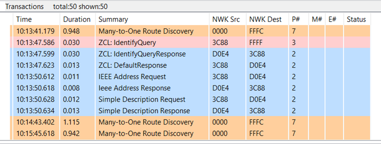
Find and bind initiator complete: 0x00You will see the log “Find and bind initiator complete: 0x00” printed on the console after the finding and binding procedure finishes. When you print the binding table on Z3Switch side (initiator), you will see the entries are created in the binding table. All the matched clusters between the initiator and target are bound. The finding and binding transactions can be found in packet trace, which proves the finding and binding working flow works as expected.
Z3Switch>option binding-table print
# type nwk loc rem clus node eui
0: UNICA 0 0x01 0x01 0x0003 0xD0E4 (>)000B57FFFE648DA0
1: UNICA 0 0x01 0x01 0x0006 0xD0E4 (>)000B57FFFE648DA0
2: UNICA 0 0x01 0x01 0x0008 0xD0E4 (>)000B57FFFE648DA0
3 of 10 bindings usedLet’s summarize how the finding and binding procedure works.
On the target side, it will write the Identify Time attribute for EMBER_AF_PLUGIN_FIND_AND_BIND_TARGET_COMMISSIONING_TIME. During the duration, the initiator broadcasts Identify Query and the target responds Identify Query Response. Then the initiator sends IEEE Address Request to the target to get the EUI64 of target, which will be used in creating binding table. The Simple Descriptor Request will be sent to target to get the clusters info on target side. Once the clusters matched, the entries will be created in binding table of initiator.
Manufacturer’s Extensions#
There are some standard profilers and clusters that can be used in Zigbee specification. This allows Zigbee devices in the market built by different manufactures to be compatible with one other. But manufacturers are free to extend the standard, so we will find how to extend it.
Types of Manufacturer Specific Extensions#
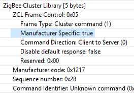
All communications regarding manufacturer specific extensions shall be transmitted with the manufacturer specific sub-field of the frame control field set to 1 and the manufacturer code included in the frame. This is because different manufactures may specify the same cluster.
Usually, there are four ways to add manufacturer specific extensions within Zigbee.
Using the Private Profile
Zigbee devices must have the same profile ID in order to interact on the application layer with each other
Use a private Zigbee profile only if you are planning to build a completely closed system
The devices using private profile will not be interoperable with any other Zigbee devices using other profiles
Extending the Manufacturer Specific Clusters
Must use cluster ID range 0xfc00 – 0xffff
Must have an associated two-byte manufacturer code
All commands and attributes within a manufacturer-specific cluster are also considered manufacturer-specific
Extending the Manufacturer Specific Commands in Standard Zigbee Cluster
May use the entire command ID range 0x00 – 0xff
Must provide an associated two-byte manufacturer code
Extending the Manufacturer Specific Attributes in Standard Zigbee Cluster
May use the entire attribute address range 0x0000 – 0xffff
Must provide an associated two-byte manufacturer code
For reading a manufacturer-specific attribute you must use the following functions
emberAfReadManufacturerSpecificServerAttribute
emberAfReadManufacturerSpecificClientAttribute
There are manufacturer-specific attribute changed callbacks that are independent from the standard attribute callbacks
emberAfXXXXClusterServerManufacturerSpecificAttributeChangedCallback
Adding Manufacturer’s Extensions to Simplicity Studio#
There are only two steps to apply the manufacturer’s extensions to Simplicity Studio.
Create a custom xml and put it to stack directory
Example: app\zcl\custom-enhancements.xml
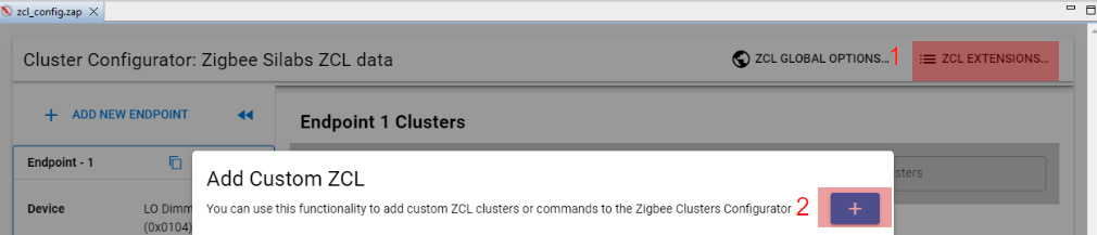
Add the custom xml to the zcl-config.zap tab under project.slcp > Configuration Tools > Zigbee Cluster Configurator
Click ZCL Extensions > Add Custom ZCL
Save and reopen the .slcp file
Note: This is used for EmberZnet 7.x
Custom Manufacturer Specific Clusters#
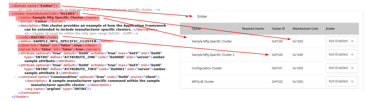
This is an example to introduce how to add a custom manufacturer specific clusters. We need prepare a xml file by ourselves firstly. Usually we should set the properties appropriately in the xml file. The properties includes configurator, cluster, name, domain, description, code, define, client, server, attribute, command. After the xml file is prepared, then put it to the correct directory and add it to Simplicity Studio.
You can see how these properties displayed in Simplicity Studio via below pictures
Properties: cluster, name, domain, code, client, server
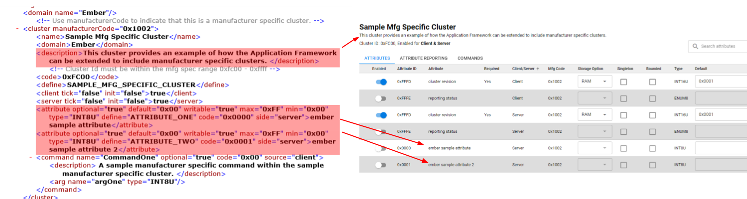
Properties: description, attribute
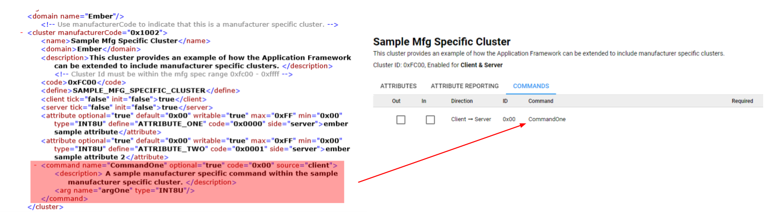
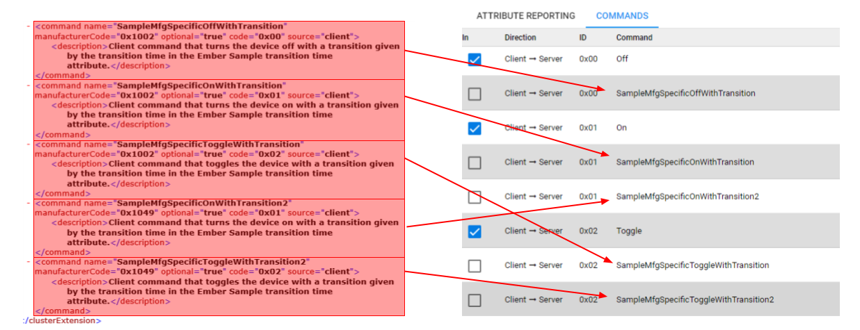
Properties: command
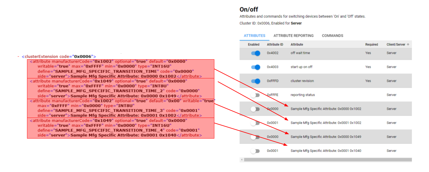
Custom Manufacturer Specific Attributes in On/Off Cluster#
As we know, the On/Off cluster is a standard cluster which defined in Zigbee Cluster Library, it has some attributes like On/Off, Global Scene Control, On Time, Off Wait Time and so on. If we want to add some custom attributes to the cluster, we need prepare the xml file and set the properties appropriately. After install the custom xml to Simplicity Studio we will see the specific attributes in On/Off cluster.
Below is an example to introduce how to add custom manufacturer specific attributes in standard Zigbee On/Off cluster.
Custom Manufacturer Specific Commands in On/Off Cluster#
The On/Off cluster is a standard cluster which defined in Zigbee Cluster Library, it has some commands like On/Off/Toggle and so on.
After install the custom xml to Simplicity Studio we will see the specific commands in On/Off cluster.
Below is an example to introduce how to add custom manufacturer specific commands in standard Zigbee On/Off cluster.
Poll Control Cluster#
Need of the Poll Control Cluster#
Problem#
The primary issue is a combination of two mechanisms which cause problems for sleepy end devices receiving messages.
First is the duration of time that the parent device stores messages for their children. This is only 7.68 seconds before a message is lost. This means that a message going from a router to an end device through another router (for example A -> B -> C, where A and B are routers and C is a sleepy end device), the message is held in the parent of the end device (B in this case). And the end device must poll within 7.68 seconds of receiving the message or the message times out of the queue. Messages can be resent, but this small window means a SED must poll frequently to receive messages.
But as we know, many customers sleepy end devices are powered by batteries and want the longest life possible, years in many cases. In order to save battery life, SED manufacturers prefer to have their devices sleep as long as possible. This usually results in polling intervals much longer than 7.68 seconds. This means that unless a SED is very lucky in polling at the right time, it will many times miss messages.
As a result sleepy end devices may miss the messages sent from other devices due to lack of polling frequency and this means that any sort of management by the controller is extremely difficult.
Solution#
In order to overcome this problem, the Poll Control cluster is used to provide a mechanism for the management of a sleepy end device’s data poll rate. It can be used by a configuration device to make an end device more responsive for a short period of time, polling at a very high rate, also known as fast polling, so that the device can more reliably receive message and be managed by the controller.
Poll Control Cluster#
The Poll Control cluster is a cluster that is defined in the Zigbee Cluster Library Specification. It is similar as other ZCL clusters in that it operates as in a server-client model. There is a Poll Control client and Poll Control server.
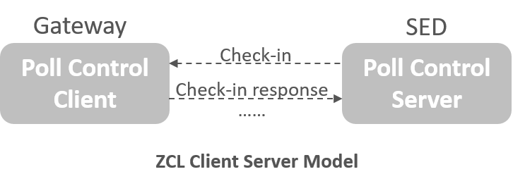
Now the confusing parts are which roles are played by each device. We normally think of a server as the always on device and a client the one that checks in. However in the Poll Control cluster, usually the Gateway acts as client and the sleepy end device works as the server. This is the case because the generally the server checks in with the client, which then sends commands to operate the server.
In the Poll Control cluster, once the SED server checks in with the client (usually a router), the client manages the data polling rate of the sleepy end device using four different commands:
0x00 - Check-in Response (Mandatory): When a server checks in, the client uses this to respond if it wants to enter fast polling mode or not.
0x01 - Fast Poll Stop (Mandatory): This tells a server that the client is finished sending messages and it can return to it’s regular polling interval.
0x02 - Set Long Poll Interval (Optional): set the long interval by which the end device polls
0x03 - Set Short Poll Interval (Optional): set the short interval by which the end device polls
The poll control cluster server defines one Check-in command and several polling interval attributes. Some of the attributes are mandatory, the others are optional.
Command
0x00 - Check-in (M)
Attributes
0x0000 - Check-inInterval (M)
0x0001 – LongPollInterval (M)
0x0002 – ShortPollInterval (M)
0x0003 – FastPollTimeout (M)
0x0004 - Check-inIntervalMin (O)
0x0005 - LongPollIntervalMin (O)
0x0006 - FastPollTimeOutMax (O)
You can refer to the ZCL specification for a more detailed explanation about these commands and attributes.
Attribute Settings and Battery Life Considerations#
The sleepy end device works as Poll Control server and can be managed by Poll Control client. In order to help conserve battery life sleepy end devices have two attributes which set bounds on the time they are allowed to be kept awake and more importantly, turn on their radios to check in.
Check-inIntervalMin - Provide minimum value for the Check-inInterval to protect against the Check-inInterval being set too low and draining the battery on the device
FastPollTimeOutMax - Provide maximum value for the FastPollTimeout to avoid it being set to too high a value resulting in an inadvertent power drain on the device
The default values chosen for this cluster are:
Check-in Interval = 1 hour = 0x3840 quarter seconds
Long Poll Interval = 5 seconds = 0x14 quarter seconds
Short Poll Interval = 0.5 second = 0x02 quarter seconds
Fast Poll Timeout = 10 seconds = 0x28 quarter seconds
It also requires that the Check-in interval >= Long Poll interval >= Short Poll interval
It should also be noted that Fast polling mode will operate so long as the client is sending data to the server/end device. So these values only come into play once fast polling data transfers are complete.
How does the Poll Control cluster work#
In some practical user cases we need to use the Poll Control cluster for sleepy end device. For example: the sleepy end device receives an OTA update from the OTA server or the billing information being downloaded from the meter.
So here we have a sleepy end device/Poll Control server and router on the network/Poll Control client. This client/router will want to send data to the SED at certain intervals.
Normally when a SED wakes up, it polls its parent for data and then go back to sleep. But this is where the Poll Control cluster operations step in.
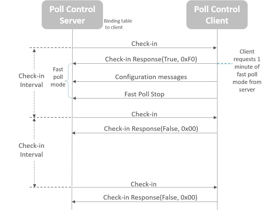
When the devices first come up, usually during device discovery, the Poll Control client configure bindings on the device implementing the Poll Control server. This will initiate the server sending Check-in commands to client.
Server sends Check-in to client periodically and the Check-in interval is guaranteed.
Note: On a normal check in, the client will return FALSE and the SED returns to sleep.
Client responds Check-in Response with True if the client wants to configure server, responds with False if nothing need to configure.
Server enters fast poll mode if the Check-in Response is True.
Client can configure the server when the server is in the fast poll mode.
Client can send Fast Poll Stop after the configuration.
From all above we can see that the Poll Control cluster allows you to configure end devices in a way that maximizes their sleep time while allowing them to have intervals where they receive data from other nodes on the network easily and efficiently.