Component Customizations#
One way to customize your NCP design is through the component configuration. Examples of common customizations follow. On the Software Components tab, use Search and the filters to find the referenced components.
Default Pins#
For EFR32 platforms, to change the default pins used for EZSP-SPI or EZSP-UART communication, use the following instructions:
For SPI NCP designs:
Install the SPI NCP Configuration component. This should already be installed if you are starting from the NCP SPI example application. In the component configuration options, check that the Selected Module setting matches your desired USART for SPI NCP communication and that the LEGACY_NCP_SPI_WAKE_INT and LEGACY_NCP_SPI_HOST_INT pin settings match your desired signal pinout for SPI communication.
For UART NCP designs:
Select the vcom component and install it if it is not already installed. In the Component Editor, on the SL_IOSTREAM_USART_VCOM card, verify that the Selected Module setting matches your desired USART Port for UART NCP communication.
For CPC NCP designs, no action is needed, as configuration is handled by the CPC instance.
Network and Stack Parameters#
In the Pro Stack (Common) component, change the Binding Table Size parameter to the max desired binding table size used by the NCP.
In the Security Link Keys Library component, change the Link Key Table Size parameter to the desired maximum number of unique APS link keys used by the NCP. Note that if you are configuring your NCP to act as a Trust Center with Zigbee 3.0 Security (as set in the Network Creator Security component), it is not necessary to have a unique key table entry for every device. Instead, a single security key known as a Master Key is used to compute unique keys via an AES-HMAC hash function for each device. However, supporting install-code-based keys requires a link key table with as many entries as the number of install-code-based keys you wish to support simultaneously for joining devices with install code support.
In the Pro Stack (Common) component, change the Child Table Size parameter to the desired maximum number of end device children joined directly to the NCP. Note that, while the on-screen text says the value range is 0-127, you cannot build the app if you enter a value greater than 64. The precompiled images are limited to 32 children.
In the Pro Stack (Common) component, increase/decrease other option parameters to meet your needs. You may need to reduce values like Packet Buffer Count, which has a high RAM overhead, if your build fails due to lack of available RAM in the memory map. However, note that most memory-related parameters here simply represent defaults when the NCP boots, and these settings can be overridden by the host during run-time configuration when the NCP is initialized.
Security#
For devices implementing Trust Center functionality (either as a coordinator providing centralized trust center responsibilities for the network or a router in a decentralized trust center configuration), you may wish to override the EZSP Trust Center policy’s decisions about when and how to provide the current network security key to a joining or rejoining device. The following callback provides this feature:
sl_zigbee_join_decision_t sl_zigbee_xncp_security_trust_center_join_cb(
sl_802154_short_addr_t newNodeId,
const sl_802154_long_addr_t newNodeEui64,
sl_zigbee_device_update_t status,
sl_802154_short_addr_t parentOfNewNode,
sl_zigbee_ezsp_decision_id_t decisionId,
sl_zigbee_join_decision_t joinDecision);NCP Event Definition and Handling#
Event definitions and handlers must be defined directly in the source code. More details can be found in UG491: Application Framework Developer’s Guide for SDK 7.x.
Custom Messaging#
To implement custom messages between NCP and host, the developer defines and implements the format, parsing, and serialization of the message set. The serialized messages are conveyed between NCP and host as opaque byte strings. This “extensible network coprocessor” functionality is provided by the XNCP component.
To send a custom message to the host, construct and serialize the message, then send the resulting byte string to the host using the EmberZNet PRO API function sl_zigbee_af_xncp_send_custom_ezsp_message().
After installing the XNCP component, the following callback definitions are provided through the component for custom 2-way messaging over EZSP. They should be implemented in the project callbacks file.
sl_zigbee_af_xncp_incoming_custom_frame_cb - Processing of custom incoming serial frames from the EZSP host
sl_zigbee_af_incoming_message_cb - Custom processing of received Zigbee application layer messages before passing these (through Incoming Message Callback frames) to the EZSP host
Note that custom outgoing serial frames from the NCP to the EZSP host should be provided as response frames to the host in reply to a Callbacks EZSP command or some custom host-to-NCP EZSP command, where they can be handled by the following host-side callback:
void sl_zigbee_ezsp_custom_frame_handler(uint8_t payloadLength, uint8_t\* payload)
Serial Transport#
Since GSDK version 4.1.0.0 or EmberZNet version 7.1.0.0, users have several options for handling the serial transport of commands between the host application and NCP application. The NCP SPI and NCP UART (HW) applications have code that handles the serialization of data across the SPI or UART connection. These applications do not use CPC. In order to have the application utilize CPC to communicate to the host application, the following changes can easily be made to an existing NCP application.
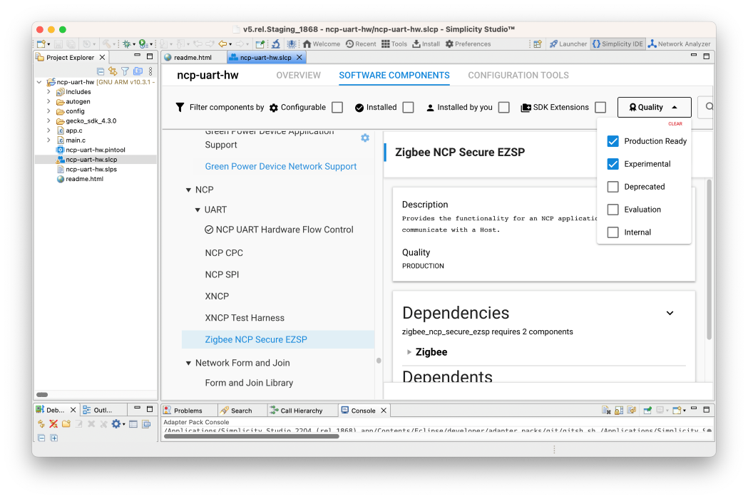
Begin by creating either the NCP SPI or NCP UART (HW) application in Simplicity Studio. The project name may be changed to ncp-cpc if desired. Once the project landing page loads, open the Software Components tab, and click the Quality filter. Make sure that Production and Evaluation components are visible. An example is shown below.
Simplicity Studio 6 (SSv6)
Simplicity Studio 5 (SSv5)
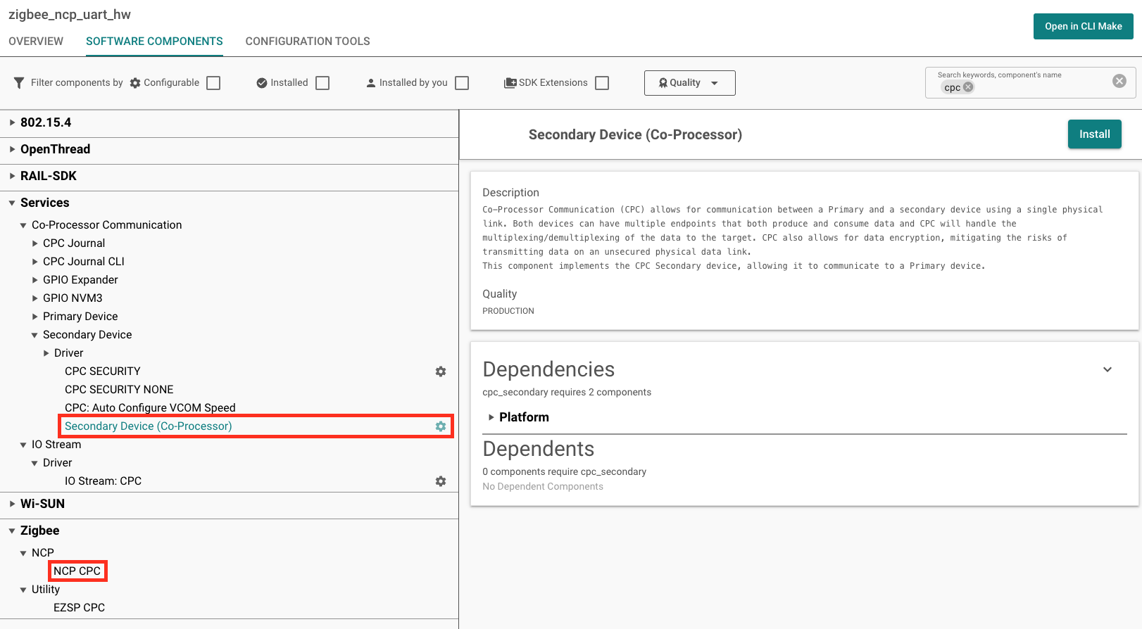
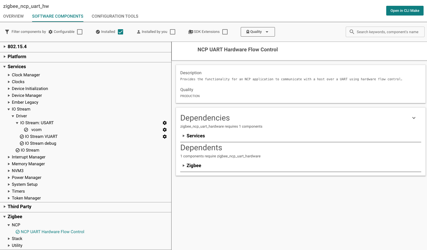
All that remains is to update the following components:
Unselect NCP UART Hardware Flow Control, if selected. This will also remove dependencies.
Unselect NCP SPI, if selected. This will also remove dependencies.
Unselect the IO Stream: USART component and its VCOM instance, if installed.
Select and install either the CPC Secondary – SPI (USART) or CPC Secondary – UART (USART) component based on the configured serial line. A popup will appear prompting for an instance name. After choosing an instance name, click Done.
Select and install NCP CPC.
Once this is complete, the project is configured. The project can now be built and flashed to an EFR32, which will allow the device to connect with a CPC-capable host application.