Physical Interface#
This section describes the EZSP-SPI Protocol pin connections and how to verify them. It also provides details on the NCP’s physical interface configuration, and on low power operation.
EZSP-SPI Protocol Pin Connections#
The physical pin connections are straightforward, and there is only a special recommendation for the nHOST_INT pin. nHOST_INT can be connected to any input. For interrupt-based operation, nHOST_INT must be connected to an external interrupt that can generate an interrupt on a falling edge. Furthermore, if the host intends to sleep and to be woken up by the NCP, nHOST_INT should be connected to a pin that is capable of waking the host. nHOST_INT should have a pull-up applied to it so that nHOST_INT does not bounce in an unknown state if the NCP is reset. An internal pull-up on the pin that nHOST_INT is connected to is acceptable.
Connect the three SPI signals (MOSI, MISO, and SCLK) to the host’s SPI. Connect nSSEL to any output from the host that can operate Slave Select. For many microcontrollers, nSSEL will simply be connected to a general-purpose output. Connect nWAKE and nRESET to any general-purpose output from the host (remember, the NCP supplies an internal pull-up on both the nWAKE and nRESET pins).
Verifying EZSP-SPI Protocol Pin Connections#
Once all of the signals are connected and a logic analyzer is attached, begin by pulling the nRESET signal low for a short period to reset the NCP. The required duration of the low nRESET for the EFR32 is at least 35 ns. nHOST_INT will return to idle (go high) almost immediately after reset (if it is not already). Note that nHOST_INT will not be driven high by a reset, but instead will default to an input. Therefore, if an external pull-up is not applied to nHOST_INT, it is possible for nHOST_INT to not go high immediately after reset but a short while later. During the startup sequence, the NCP will switch nHOST_INT to an output and actively drive it high. After approximately 250 ms, the nHOST_INT signal will assert (go low) and stay asserted until the host initiates a transaction. The startup time of the NCP can vary widely, but 1,100 ms is a good rule of thumb for when nHOST_INT will assert after reset. nHOST_INT asserting after pulling on the nRESET pin indicates that both the nRESET pin and nHOST_INT are connected and operating correctly. If nHOST_INT is tied to an external interrupt on the host, this is also a good time to test the interrupt generation by pulling on the nRESET pin to trigger nHOST_INT assertion.
Testing the three SPI signals (MOSI, MISO, and SCLK) is best done by formulating a complete transaction. Unfortunately, the nWAKE signal cannot be used or tested until a first, complete transaction has occurred refer to SPI Protocol Version. This is because the nHOST_INT signal must deassert after reset for a proper Wake Handshake to be performed. Once a complete transaction has finished and nHOST_INT has deasserted, nWAKE may be asserted. After nWAKE asserts, nHOST_INT will assert in response, indicating that the nWAKE signal is connected properly.
Physical Interface Configuration#
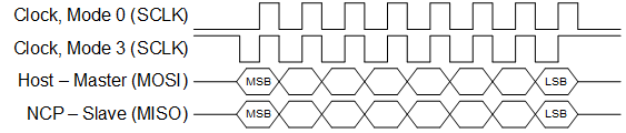
The NCP supports both SPI Slave Mode 0 (clock is idle low, sample on rising edge) and SPI Slave Mode 3 (clock is idle high, sample on rising edge) as illustrated in the following figure. The maximum SPI clock rate is documented in the NCP’s reference manual. The convention for the waveforms in this document is to show Mode 0.
The nHOST_INT signal and the nWAKE signal are both active low. The Host must supply a pull-up resistor on the nHOST_INT signal to prevent errant interruptions during undefined events such as the NCP resetting. The NCP supplies an internal pull-up on the nWAKE signal to prevent errant interruptions during undefined events such as the Host resetting.
Low-Power Operation and Signal Configurations#
To minimize current consumption, the host should use matching pin configurations. While the NCP supports both Mode 0 and Mode 3, the NCP uses Mode 0. This means that when the NCP is awake, the idle state of the clock is low. When the NCP is sleeping, the host needs to use a configuration that does not conflict with the NCP’s configuration to achieve the lowest power. (See also Waking the NCP from Sleep.) The following table describes the NCP’s signal configuration in sleep.
Signal | Configuration |
|---|---|
MOSI | input, pullup |
MISO | input, pullup |
SCLK | input, pullup |
nSSEL | input, pullup |
nHOST_INT | input, pullup |
nWAKE | input, pullup |