Working with Examples#
In these instructions you will work with two example applications, Zigbee - Z3Light Application and Zigbee - Z3Switch Application. These steps illustrate both how to compile and load example applications and use the Simplicity Studio console interface to work with them, but also how to configure them using three configuration tools:
Simplicity Studio’s Project Configurator allows you to add and remove functions from the applications in the form of components
The Component Editor allows you to change the parameters of components installed in the application
The Zigbee Cluster Configurator allows you to modify Zigbee clusters, attributes, and commands.
The following example procedures are provided. Each procedure builds on the next, so it is recommended to work through them in order.
Create and Load a Zigbee - Z3Light Application : Provides a detailed walk-through of project creation.
Create and Load a Zigbee - Z3Switch Application : Provides some shortcuts to project creation.
Create a Distributed Network and Issue Commands : Shows how to use the Console interface, create a network, and turn a light on and off.
Change to a Centralized Network : Describes how to use the Project Configurator and Component Editor to change an application.
About the Zigbee Cluster Configurator: Introduces additional configuration options provided through the Zigbee Cluster Configurator.
About Bootloaders provides instructions on uploading a bootloader image. This should not be necessary unless you erase the device.
Section Using the Network Analyzer describes how to use Network Analyzer to observe traffic across the network.
These procedures are illustrated for a WSTK with an EFR32MG. >Note: Your SDK version may be later than the version shown in the procedure illustrations.
Create and Load a Zigbee - Z3Light Application#
SSv5 offers a variety of ways to begin a project using an example application. The online Simplicity Studio 5 User’s Guide, available both through https://docs.silabs.com/ and the SSv5 help menu, describes them all. This procedure uses the File > New > Silicon Labs Project Wizard method, because it takes you through all three of the Project Creation Dialogs.
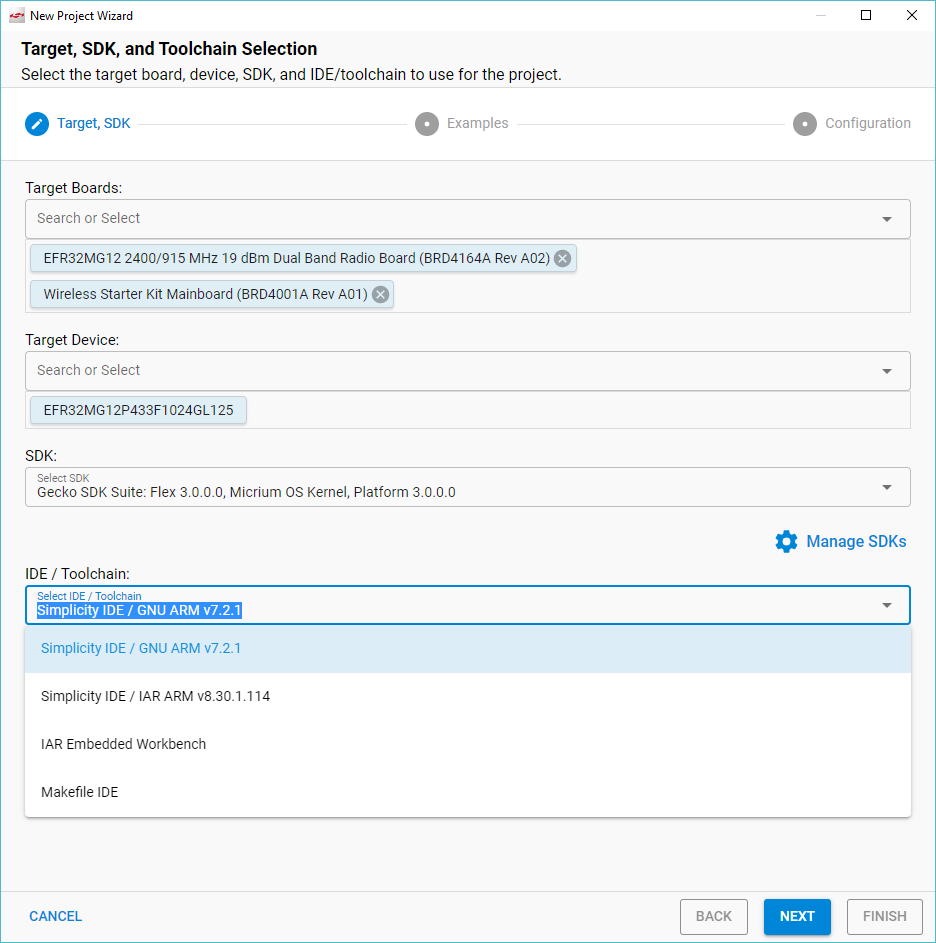
Open SSv5’s File menu and select New > Silicon Labs Project Wizard. The Target, SDK, and Toolchain Selection dialog opens. If you want to change the toolchain from the default GCC to IAR, do so here. Click NEXT.
Note: If you have both IAR and GCC installed, GCC is the default.
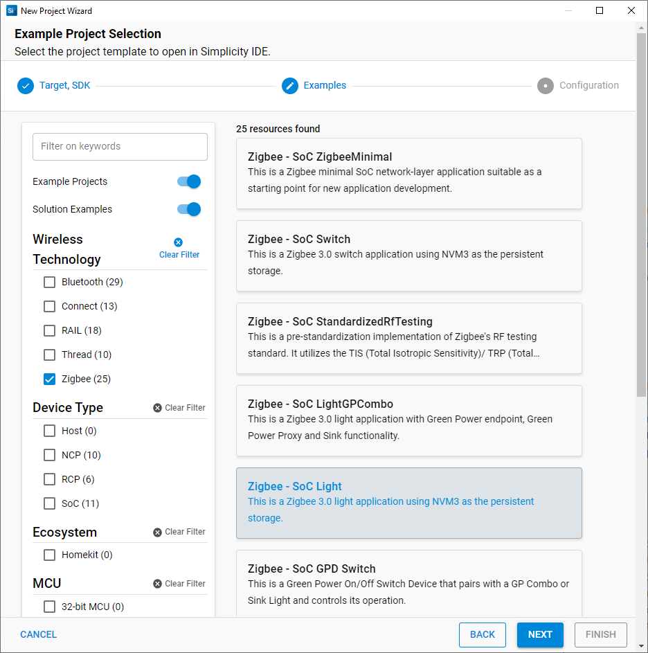
The Example Project Selection dialog opens. Use the Technology Type and Keyword filters to search for a specific example, in this case Zigbee - Z3Light. Select it and click NEXT.
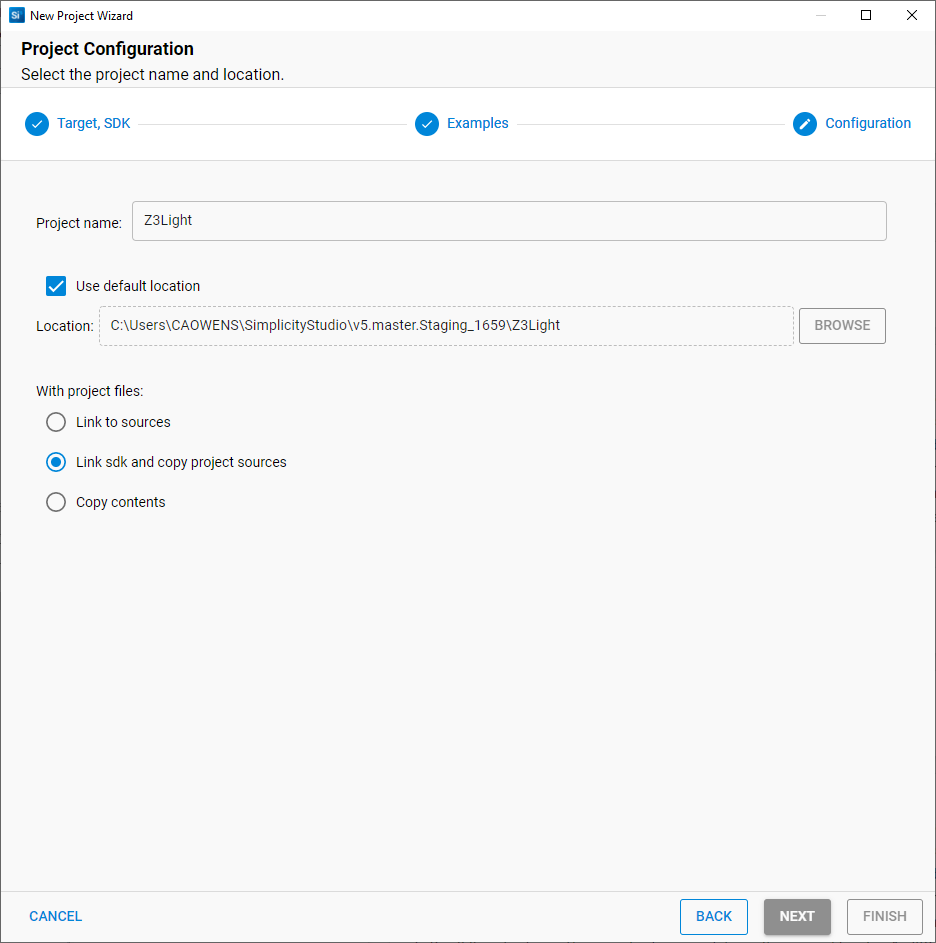
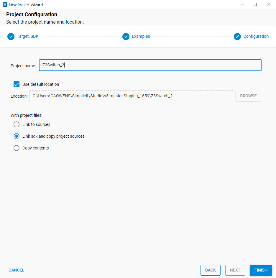
The Project Configuration dialog opens. Here you can rename your project, change the default project file location, and determine if you will link to or copy project files. Note that if you change any linked resource, it is changed for any other project that references it. Click FINISH.
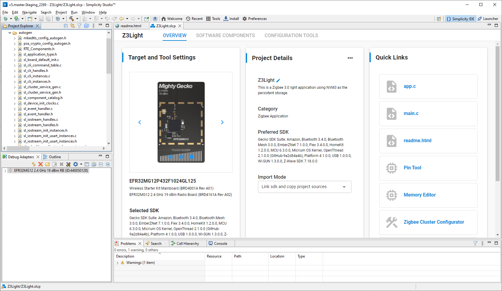
The Simplicity IDE perspective opens with the new project in Project Configurator view. The readme tab contains information about the project. See the online Simplicity Studio 5 User’s Guide for details about the functionality available through the Simplicity IDE perspective and Project Configurator.
Note: You now have a Simplicity IDE button next to the Launcher button in the upper right.
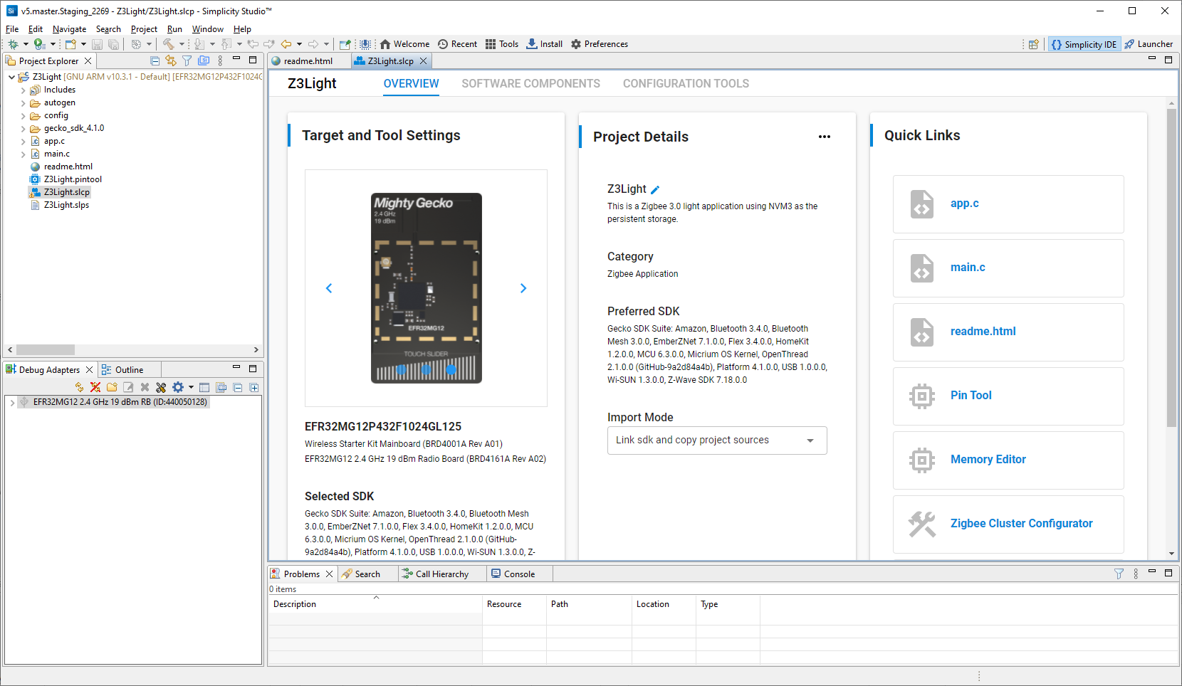
Simplicity Studio automatically generates the project files needed to build the application image. If you are accustomed to using Simplicity Studio 6.x, note that this means there is no Generate button on the Project Configurator interface. The Force Generation button on the Project Details card is not a replacement, but rather to be used under conditions in which auto-generation fails to work.
Files are created in the autogen folder, and are automatically updated when you make changes to the project configuration.
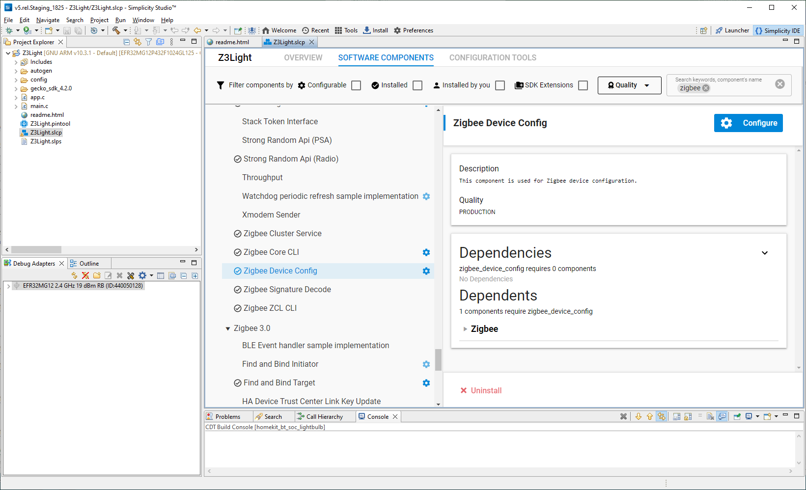
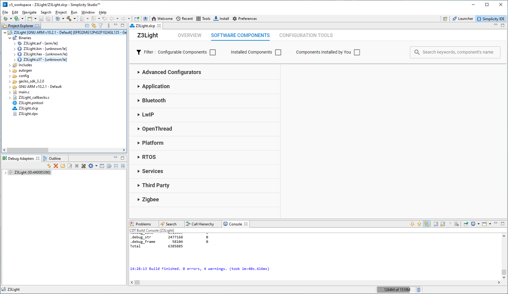
Example applications are pre-configured to support the example functionality. To see the configuration, click the SOFTWARE COMPONENTS tab and search for the component of interest, for example ‘device configuration’. Installed components are indicated by a check on the left. Configurable components are indicated by a gear icon on the right. Select the component to see more information about it.
Note: All EFR32 parts have a unique RSSI offset. In addition, board, antenna and enclosure design can also impact RSSI. When creating a new project, install the RAIL Utility, RSSI component. This feature includes the default RSSI Offset Silicon Labs has measured for each part. This offset can be modified, if necessary, after RF testing of your complete product.
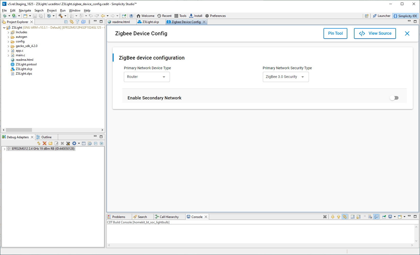
Click Configure to open the Component Editor on a new tab. The configurable parameters are shown. In this case, it indicates that the Z3Light application is configured as a router. Close the Component Editor.
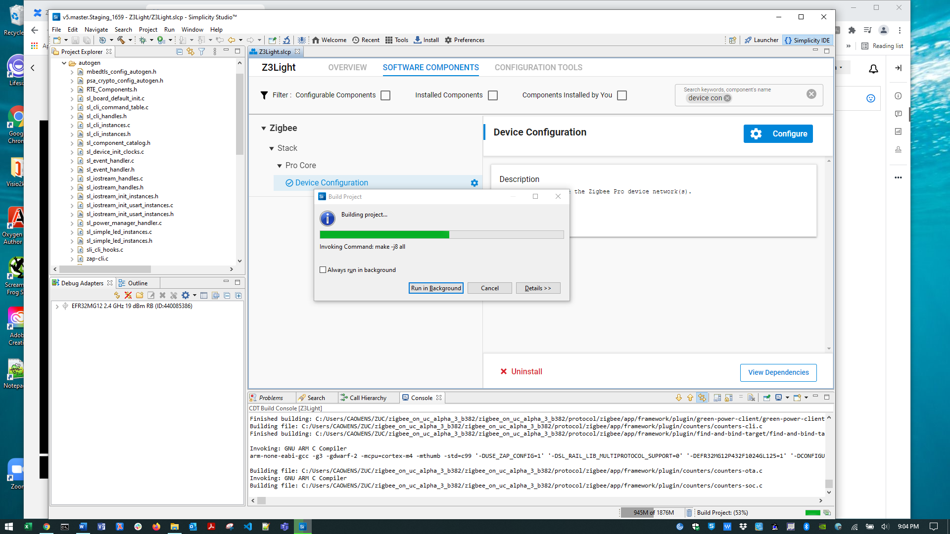
Once you are ready to build the application, click the Build (hammer) control in the top tool bar. During the build, progress is reported both in a window, which can be run in the background, and also in the lower right. The process may take over a minute.
Note: If the Build control isn’t active, click the project directory or a file in it.
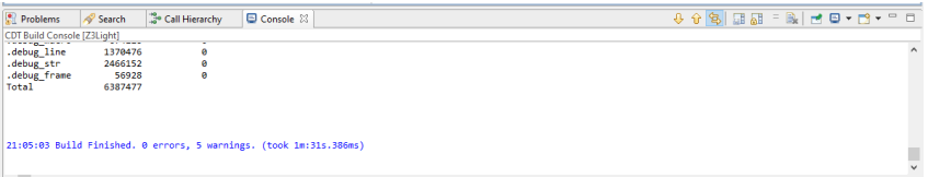
Build completion is reported in the Build Console. The build should complete without errors. If any errors occur, they are highlighted in red in the console. Contact technical support for assistance.
In the Project Explorer view, the binaries are shown in a new folder, Binaries.
Right-click the <project>.s37 file, and select Flash to Device. If you have more than one device connected, you are prompted to select the target. Then the following dialog is displayed.
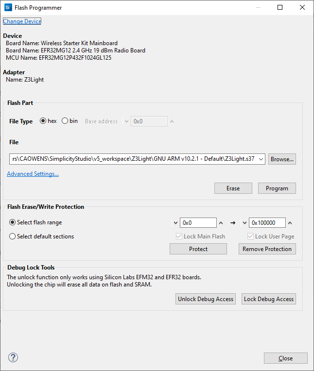
Click Program. The binary is flashed to the target device.
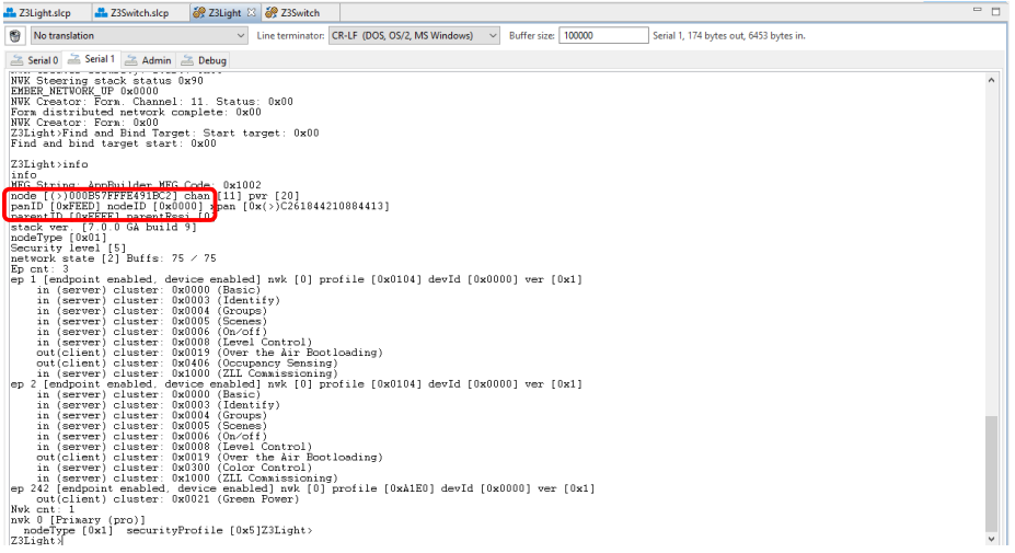
In the Debug Adapters view, right-click the Z3Light device and select Launch Console. In the console window, you will see four tabs: Serial 0 (the Virtual UART interface), Serial 1 (the physical UART interface), Admin (where you can configure the debug adapter such as the WSTK for EFR32), and Debug (where you see raw binary data over the debug interface). Click the Serial 1 tab. Type ‘info’ and press Enter.
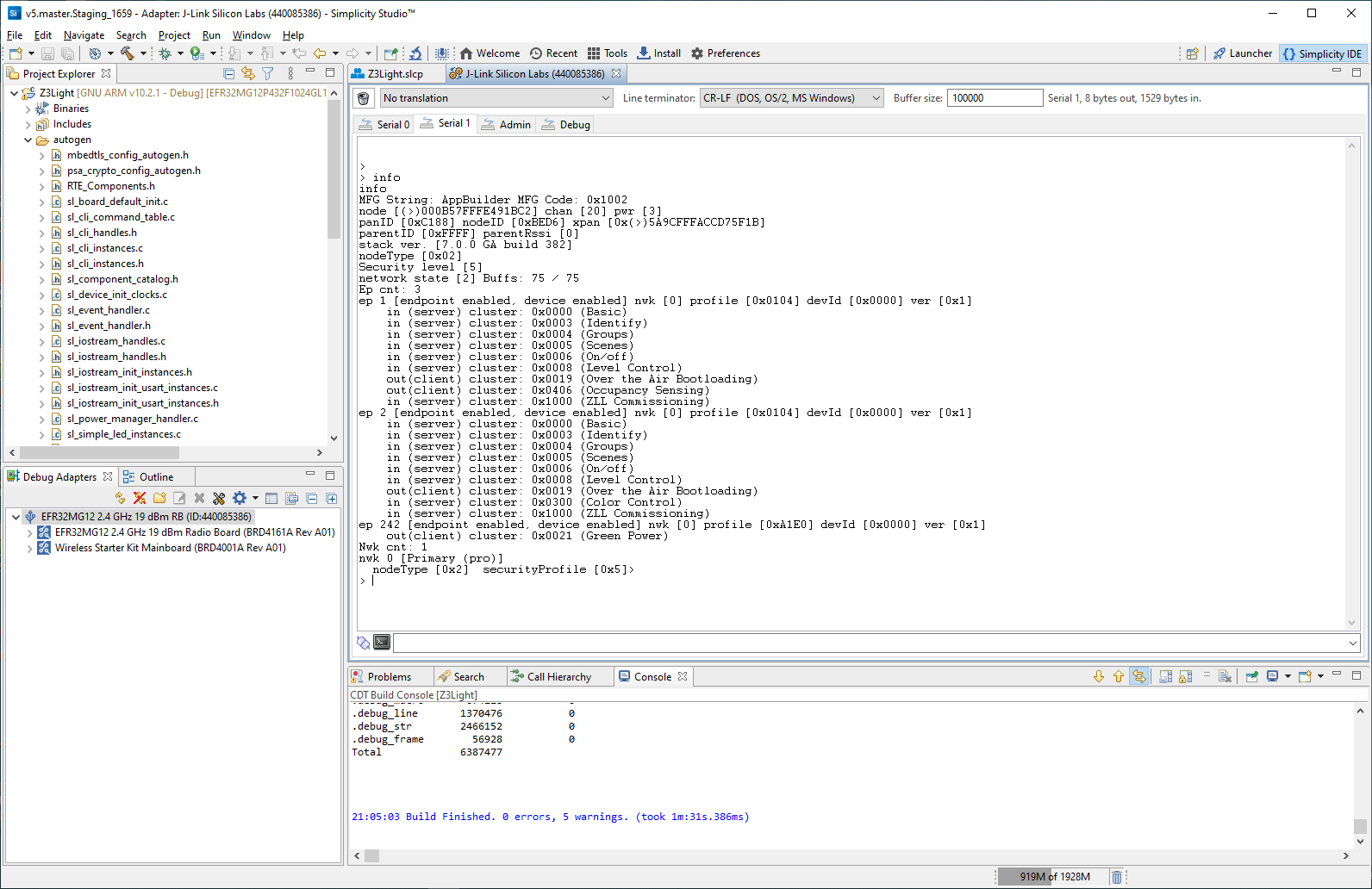
The application has created a distributed network with three endpoints, the last being the Green Power endpoint.
Note: During development you may make changes, work with the console, and then make other changes. While you can load a fresh application image with the device connected, you may have to repair the connection. Alternatively, disconnect from the console by right-clicking the device and selecting Disconnect.
If you have multiple devices connected, the device context menu also contains a Rename selection, which you can use to better identify the device roles.
Create and Load a Zigbee - Z3Switch Application#
The Zigbee - Z3Switch example procedure follows a slightly different path than that illustrated for zigbee_z3_light. Use this shorter path if you do not need to modify devices or compilers.
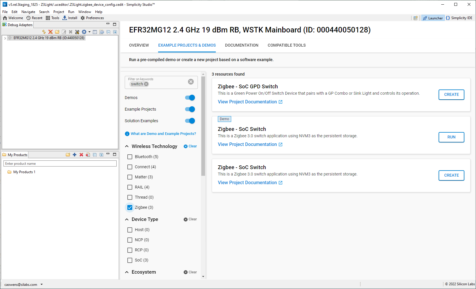
Click Launcher in the upper right to return to the Launcher perspective.
In the Debug Adapters view, select the Switch device.
Go to the EXAMPLE PROJECTS & DEMOS tab and click CREATE next to the Zigbee - Z3Switch application.
This opens the third of the three project creation dialogs illustrated in the zigbee_z3_light process. Change any values you wish to change, and click FINISH.
The project opens. All files are autogenerated. The Z3Switch application is configured as an end device.
Click the Build (hammer) control to build the application.
When the build is complete, right-click the <project>.s37 file and select Flash to Device. Click Program.
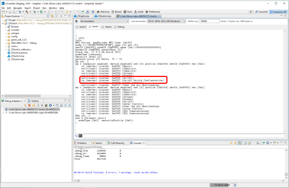
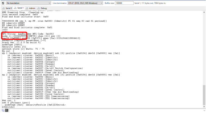
When upload is complete, right-click the Switch device and select Launch Console. Select the Serial 1 tab, and enter ‘info’. The output should resemble the following. The switch has not yet joined a network.
Create a Distributed Network and Issue Commands#
Once you have downloaded both the light and switch applications to different radio boards, you can create a network. Make sure that the switch device is physically close to the light device.
To see the process from beginning to end, close the distributed network created automatically on the zigbee_z3_light device. In the zigbee_z3_light console, enter:
> network leave
Then form the network:
> plugin network-creator start 0
Open the network for joining:
> plugin network-creator-security open-network
You now have 55 seconds to join the switch to the open network. On the zigbee_z3_switch console, enter:
> plugin network-steering start 0
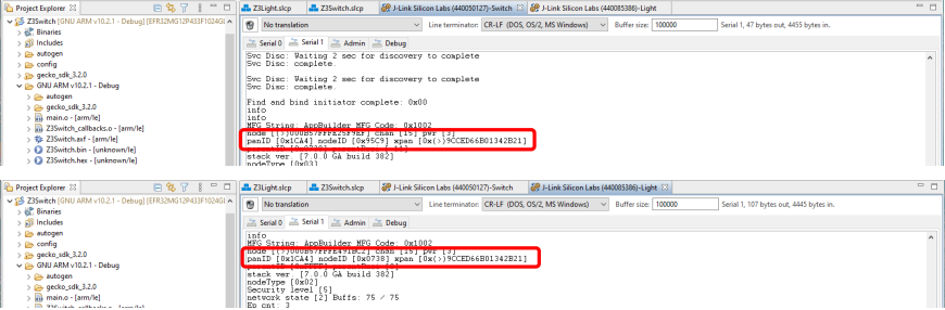
Enter info on both devices and you will see that both the light and switch are on the same PAN ID.
To send a command from the switch to the light, first build the toggle command and load it into a TX buffer:
> zcl on-off toggle
Then send the command to the light, using the device’s Node ID (also known as the short ID), which is 0x0738. To toggle the device’s LED on and off, on the zigbee_z3_switch device enter:
> send 0x0738 1 1
The light console should show:
T00000000:RX len 3, ep 01, clus 0x0006 (On/off) FC 01 seq 01 cmd 02 payload[]
On/Off set value: 01 02
Toggle on/off from 00 to 01On the WSTK board, LED1 should turn on.
Change to a Centralized Network#
In a distributed network, any router can issue network security keys. In a centralized network, a coordinator has the functionality of a Trust Center. Each node that joins is authenticated by the Trust Center before it can join the network. The coordinator is always node ID 0x0000. To change Z3Light to a Coordinator:
Go to the zigbee_z3_light.slcp tab.
On the SOFTWARE COMPONENTS tab, search for ‘device config’.
Select the Zigbee Device Config component and click Configure.
Change the Primary Network Device Type to ‘Coordinator or Router’. The change is saved automatically.
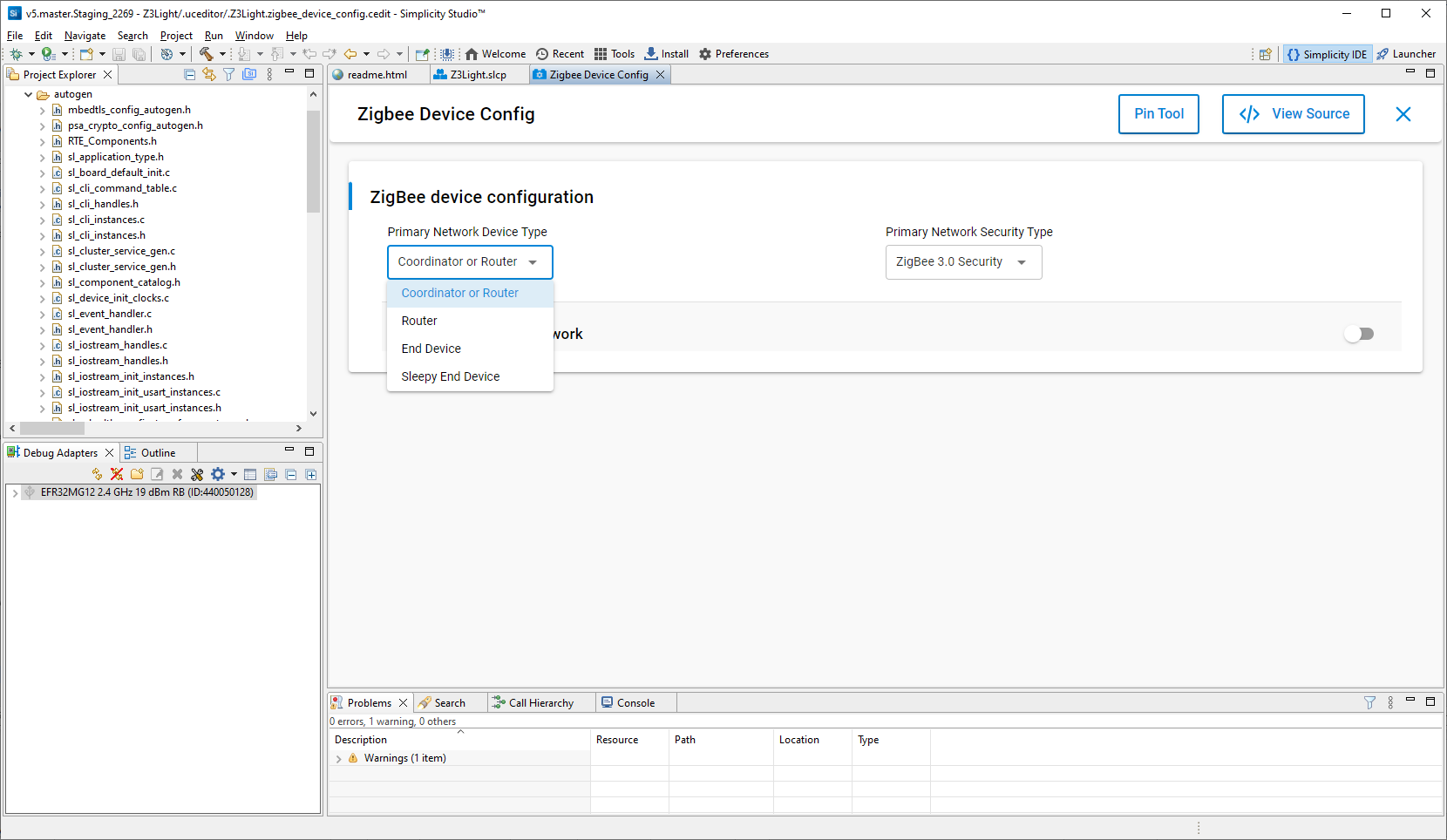
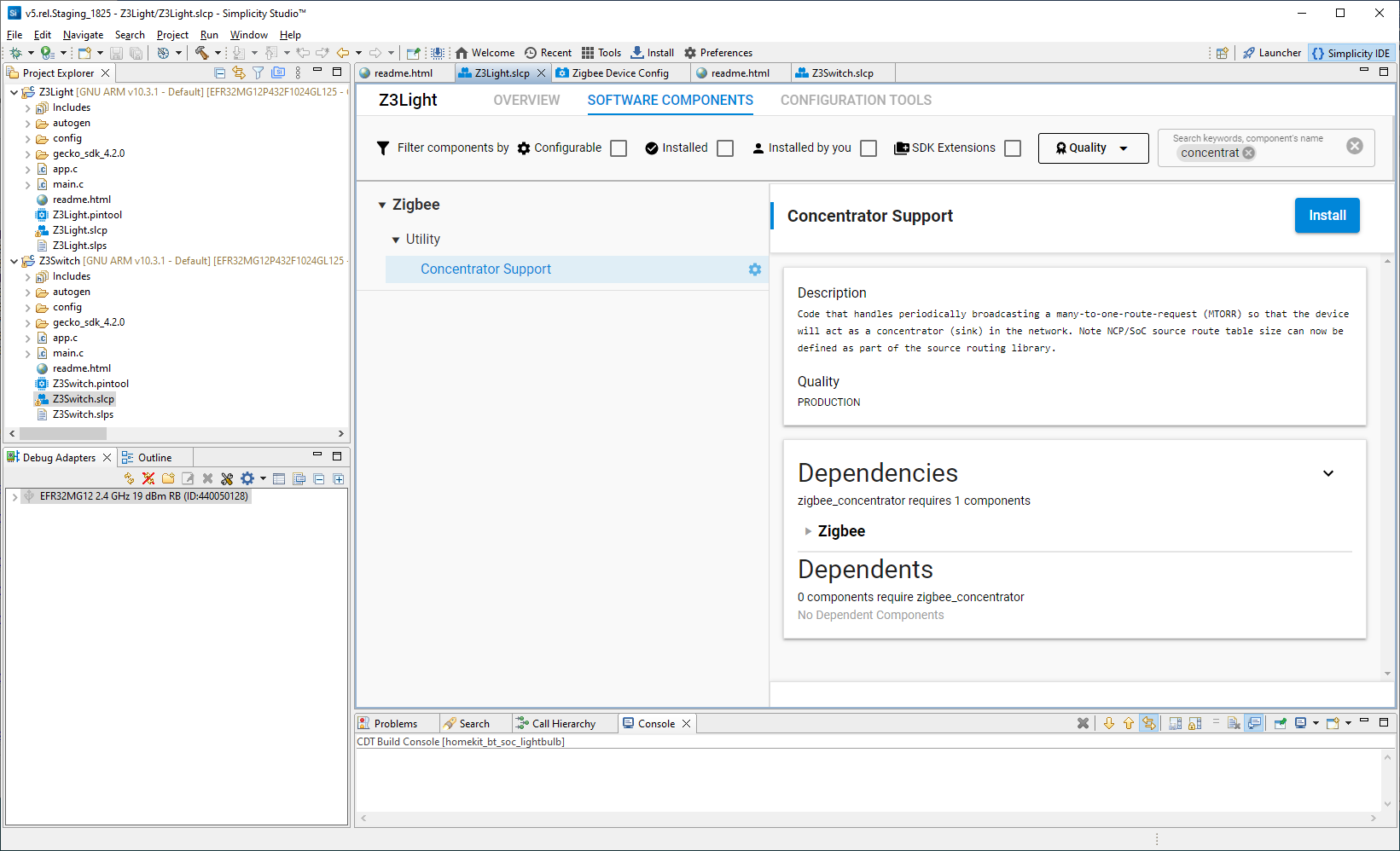
All coordinators must also have Concentrator functionality. Close the Component Editor and, back on the Software Components tab, search for ‘concentrator’.
Select the Concentrator Support component and click Install. Changes are saved automatically.
In the Project Explorer view, select zigbee_z3_light and click the Build (hammer) icon.
When build is complete, right-click the zigbee_z3_light device and click Disconnect.
When the build is complete, right-click the <project>.s37 file and select Flash to Device. Click Program.
Launch the console for the zigbee_z3_light device.
Next, take down the distributed network and start the centralized network.
> network leave
Then form the network:
> plugin network-creator form 1 0xfeed 20 11
Enter info. The PAN ID is that specified, and the Node ID is 0x000
Open the network for joining:
> plugin network-creator-security open-network
You now have 55 seconds to join the switch to the open network. On the switch device:
> network leave
> plugin network-steering start 0Enter info. The PAN ID is that specified, and the parent ID is 0x0000.
To send a command from the switch to the light, first build the toggle command and load it into a TX buffer:
> zcl on-off toggle
Then send the command to the light, using the device’s Node ID 0x0000. To toggle the device’s LED on and off, on the zigbee_z3_switch device enter:
> send 0 1 1
The light console should reflect the command and, on the WSTK board, LED1 should toggle from its previous state.
About the Zigbee Cluster Configurator#
Additional customizations can be made through the Zigbee Cluster Configurator. Using this tool is described in detail in AN1325: Zigbee Cluster Configurator User’s Guide.
About Bootloaders#
All Silicon Labs examples require that a bootloader be installed. A bootloader is a program stored in reserved flash memory that can initialize a device, update firmware images, and possibly perform some integrity checks. Silicon Labs networking devices use bootloaders that perform firmware updates in two different modes: standalone (also called standalone bootloaders) and application (also called application bootloaders). An application bootloader performs a firmware image update by reprogramming the flash with an update image stored in internal or external memory. For more information about bootloaders see UG103.6: Application Development Fundamentals: Bootloading.
In March of 2017, Silicon Labs introduced the Gecko Bootloader, a code library configurable through Simplicity Studio’s IDE to generate bootloaders that can be used with a variety of Silicon Labs protocol stacks. The Gecko Bootloader is used with all EFR32xG parts.
The Gecko Bootloader works with a specialized firmware update image format, ending in the extension .gbl (the GBL file). To create a GBL file from an .s37 or binary, follow the instructions in Simplicity Commander Reference Guide. The exact format of the GBL file depends on the hardware you selected.
Note: When working with the Gecko Bootloader, you must use Simplicity Commander to enable some configuration option such as security features. See UG489: Silicon Labs Gecko Bootloader User’s Guide for GSDK 3.3 and Higher.
By default, a new device is factory-programmed with a bootloader. If you have a new device, haven’t cleared the bootloader region for your part or have a supported bootloader image already flashed on your device, you do not need to flash a bootloader. Once you have installed a bootloader image, it remains installed until you erase the device.
If you need to load a bootloader, select an example, such as SPI Flash Storage Bootloader (single image), and build it and flash it as described above. For more information about the Gecko Bootloader, see UG489: Silicon Labs Gecko Bootloader User's Guide for GSDK 4.0 and Higher.