Test Network and Conditions#
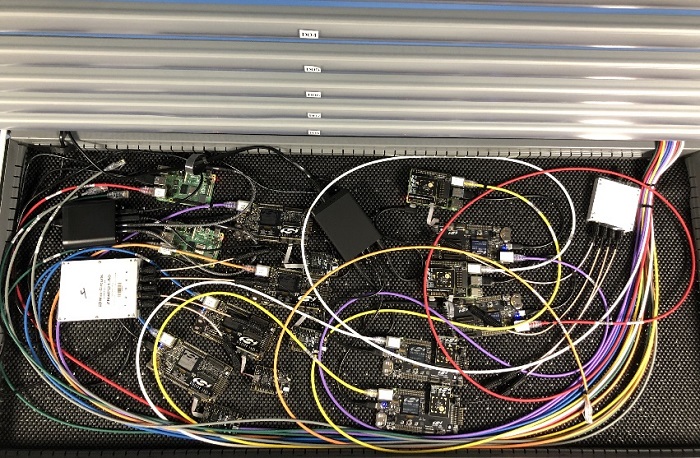
To minimize variability, device testing can also be performed in fixed topologies where the RF paths are wired together through splitters and attenuators to ensure the topology does not change over time and testing.
A typical wired test configuration is shown below:
Large network testing is best conducted in an open-air environment where device behavior is based on the existing and varying RF conditions. The Silicon Labs R&D facility is used for this open-air testing.
Facility and Test Network Conditions#
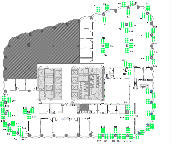
The Silicon Labs R&D facility consists of a central core with an elevator shaft, other services with an open floor plan in parts with offices and conference rooms spread about The overall facility measures approximately 120 feet by 200 feet. The image below shows the facility layout. The darker lines represent hard walls and everything else is split up with cube partitions.
The testing devices are installed at various locations around the facility. These devices all have Ethernet backchannel connectivity to allow:
Firmware updates
Command line interface
Scripting
Timing analysis
Packet capture
Energy measurements
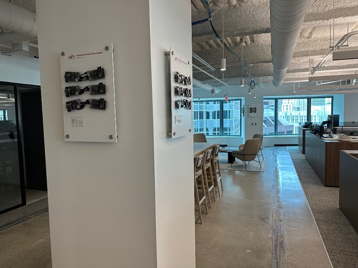
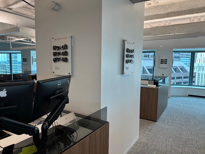
The testing cluster in the following figure includes:
Six EFR32MGxx Devices
Multi-band support to allow testing both 2.4 GHz (PCB antenna)
USB power and Ethernet connectivity
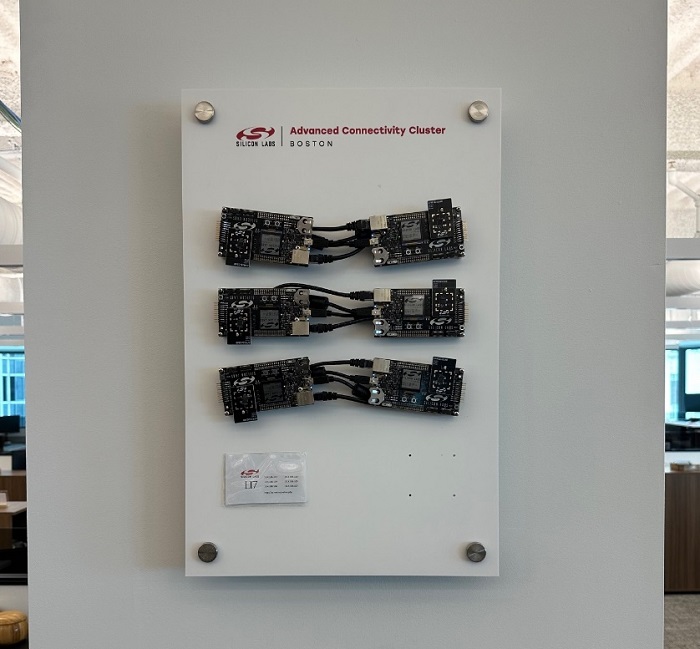
The testing clusters are spread throughout the facility in both high and low locations, open areas, and enclosed meeting rooms and offices.
This test network has devices added or removed from it on a regular basis, but at the time of this testing it consisted of EFR32MG24.
This network represented devices that were used for open-air testing by the networking and software quality assurance teams. All devices are controlled from a central test server and infrastructure, which allows scripted regression testing or manual testing by engineers.
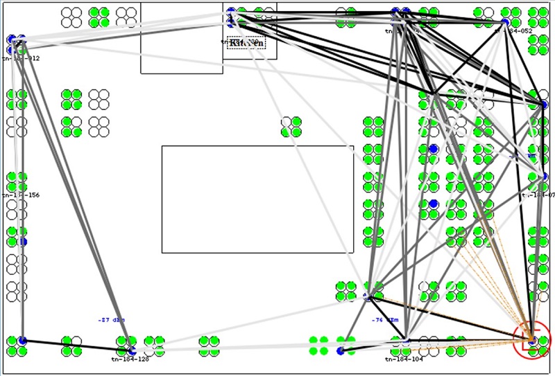
Typical Test Network#
Within the test network, a given test can be selected and used for a given set of devices. The network is established and devices joined using the Ethernet backchannel to send commands to devices. A typical network during testing is shown below. The black and grey lines show the router connectivity and strength.