Integrating External Semtech Radios#
This section details the hardware and software steps necessary to connect and configure external sub-GHz transceivers, specifically the Semtech SX1262 and LR1110, for use with the Sidewalk SDK. This includes SPI connectivity, IRQ handling, and radio-specific driver configuration.
For KG100S based custom hardware, you can directly add the KG100S software component and the SX1262 driver to have the correct configuration and radio handling for this module.
The Sidewalk qualification app is the recommended starting point for hardware porting. It provides a validated foundation with Sidewalk messaging and registration logic already implemented and is used to submit a qualification request to Amazon. This section explains how to adjust the application for your custom board and links to its usage guide.
Hardware Interface#
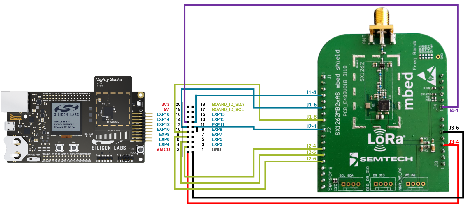
External transceivers like the SX1262 and LR1110 require proper SPI and GPIO integration for Sidewalk communication. This section covers physical wiring of the radio interface, including mandatory connections for IRQ, reset, and busy lines, as well as reference schematic guidelines.
For SX1262, 8 GPIOs need to be wired between your EFR32 chip and the Semtech transceiver:
BUSY: Used to indicate the status of internal state machine.
ANTSW: External antenna switch to control antenna switch to RECEIVE or TRANSMIT.
DIO: IRQ line from SX126x chip. See SX126x datasheet for IRQs list.
NRESET: Factory reset pin. Will be followed by standard calibration procedure and previous context will be lost.
SPI_TX: SPI TX line
SPI_RX: SPI RX line
SPI_CLK: SPI clock source
SPI_CS: SPI chip select
For LR1110, an additional GPIO is needed if you wish to leverage the GNSS and WiFi scanning features, refer to Semtech documentation for more details.
It's important to consider that each pin has different availability depending on the sleep level. If you want the EFR to wake up on a radio event, choose the DIO IRQ line accordingly.
Ⓘ INFO Ⓘ: the DIO IRQ line needs to be able to wakeup the EFR32 at least from EM2 sleep. Refer to your datasheet to select a relevant pin.
Here is an example pinout for the EFR32xG24 radio:
Signal Name | Semtech Function | EFR32xG24 Pin | Notes |
|---|---|---|---|
SPI_MOSI | MOSI | PC01 | SPI Data (Master Out) |
SPI_MISO | MISO | PC02 | SPI Data (Master In) |
SPI_SCLK | SCK | PC03 | SPI Clock |
SPI_CS | NSS | PC00 | SPI Chip Select |
DIO1 | DIO1 | PA08 | Semtech interrupt |
BUSY | BUSY | PA07 | Transceiver Busy line |
NRESET | Reset | PA09 | Reset pin |
ANTSW | ANTSW | PA06 | Antenna Switch |
This is the pinout used by our radio boards using EFR32xG24 with SX1262 through our adaptor board.
Board Support Package (BSP) Configuration#
Once the hardware interface is in place, you'll configure the software stack to recognize and use the external radio. This includes assigning GPIOs via board-specific configuration headers, and including the appropriate driver components in the project.
Install the subGHz driver that you need through the software components: Sidewalk Sub-GHz SX1262 or Sidewalk Sub-GHz LR1110. The drivers will also install the necessary dependencies, like the SPI driver.
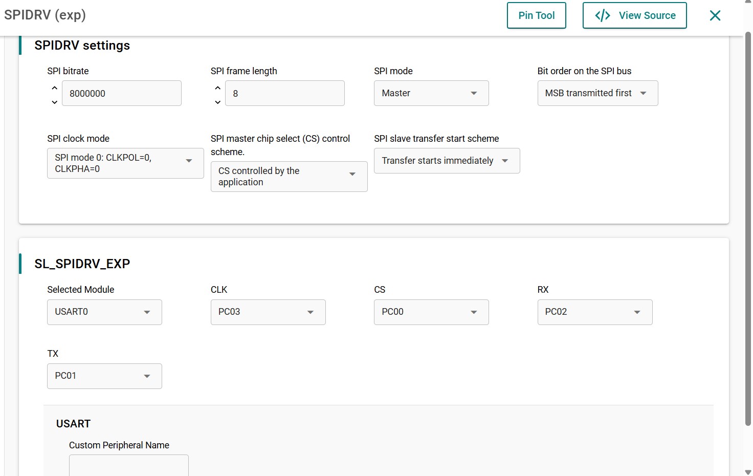
Configure the SPI driver instance (called exp by default) in your software component. You can find it under Driver - SPI - SPIDRV, click Configure. Choose the USART module you wish to use and relevant CLK, CS, TX and RX pins for your custom hardware.
For example, the EFR32xG24 with SX1262 SPI driver configuration is as follows:
Once the SPI driver is configured, go to config/app_gpio_config.h to set the BUSY, ANTSW, DIO, NRESET and CS pins corresponding to your hardware. By default those pins will be set as "NOT_CONFIGURED" and the project will not compile.
Example of config/app_gpio_config.h for EFR32xG24 with SX1262:
// BUSY on Expander Header Pin 13
// Used to indicate the status of internal state machine
#define SL_BUSY_PIN SL_EMLIB_GPIO_INIT_EXP_13_PIN // 7
#define SL_BUSY_PORT SL_EMLIB_GPIO_INIT_EXP_13_PIN // SL_GPIO_PORT_A
// ANT_SW on Expander Header Pin 11
// External antenna switch to control antenna switch to RECEIVE or
// TRANSMIT.
#define SL_ANTSW_PIN SL_EMLIB_GPIO_INIT_EXP_11_PIN // 6
#define SL_ANTSW_PORT SL_EMLIB_GPIO_INIT_EXP_11_PORT // SL_GPIO_PORT_A
// DIO1 on Expander Header Pin 12
// IRQ line from sx126x chip
// See sx126x datasheet for IRQs list.
#define SL_DIO_PIN SL_EMLIB_GPIO_INIT_EXP_12_PIN // 8
#define SL_DIO_PORT SL_EMLIB_GPIO_INIT_EXP_12_PORT // SL_GPIO_PORT_A
// SX NRESET on Expander Header Pin 14
// Factory reset pin. Will be followed by standard calibration procedure
// and previous context will be lost.
#define SL_NRESET_PIN SL_EMLIB_GPIO_INIT_EXP_14_PIN // 9
#define SL_NRESET_PORT SL_EMLIB_GPIO_INIT_EXP_14_PORT // SL_GPIO_PORT_A
#define SL_SX_CS_PIN SL_SPIDRV_EXP_CS_PIN // 0
#define SL_SX_CS_PORT SL_SPIDRV_EXP_CS_PORT // SL_GPIO_PORT_CFEM Pitfalls#
If your custom board includes a front-end module (FEM), you must ensure proper control signal routing and truth table configuration. This section highlights common issues with FEM integration and how to avoid them during bring-up.
By default the PAL layer controlling the Semtech part does not handle any specific pin for FEM, you will need to modify the code in order to handle yours. You can take example on the KG100S configuration that includes a specific RF Switch, different from the Semtech reference hardware. It is advised to control power consumption during radio events and TX output power when using a FEM. Check that both metrics corresponds to your Sidewalk configuration.
Driver-Specific Notes#
Each radio has unique characteristics that affect integration. This section outlines important implementation differences:
SX1262 supports both FSK and CSS with a single IRQ line.
LR1110 requires a more complex interface but supports the same modulations. Since Sidewalk SDK 1.19.1, GNSS/Wi-Fi are integrated into Sidewalk and allow to leverage location information directly in AWS. See the Amazon documentation on location support for more information.
If using the KG100S module (which includes the SX1262), predefined software and hardware settings simplify the process.
In KG100S applications Silicon Labs recommends not using the SPI peripheral, because the multi-chip module (MCM) design already leverages it for communication between the EFR32 and the Semtech radio transceiver. Sharing the SPI bus with additional devices or peripherals can negatively impact time-critical radio control signals and lead to message failure in sub-GHz protocols.