Controlling LEDs from a Smartphone#
Background#
This code example has a related User's Guide, here: Getting Started
Description#
An effective way to become familiar with the Silicon Labs Bluetooth stack and a Wireless Starter Kit (WSTK) is to create a simple software example to control the WSTK's LEDs with a mobile phone app, as shown in this code example.
The application has 3 main tasks, as follows:
Implement a GATT database that includes some characteristic for controlling I/O states
Control the LEDs on the board
React on Bluetooth events, e.g., when a remote device reads/writes the GATT database
The GATT Database#
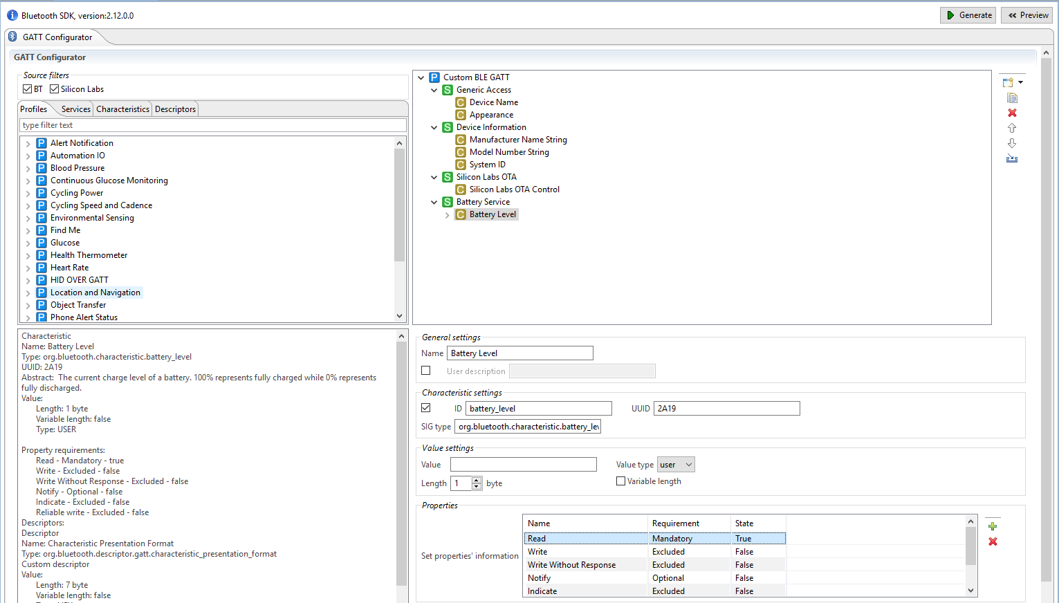
Editing the GATT database of the Bluetooth device is made easy with Silicon Labs Bluetooth SDK using the GATT Configurator as an easy-to-use graphical tool. This example shows how to add a standard characteristic, adopted by the Bluetooth SIG, to the database, the so called [Digital characteristic].
To see the format and requirements of adopted characteristics, see the list here.
The characteristic is designed to control and poll the state of digital I/Os. See the Setting up section to learn how to add this characteristic to your database.
Controlling the LEDs#
The following three functions are used in the application to initialize, control, and read the status of the LEDs:
/**
 * @brief setup_leds
 * Configure LED pins as output
 */
static void setup_leds(void) {
  GPIO_PinModeSet(BSP_LED0_PORT, BSP_LED0_PIN, gpioModePushPull, 0);
  GPIO_PinModeSet(BSP_LED1_PORT, BSP_LED1_PIN, gpioModePushPull, 0);
}

/**
 * @brief get_leds
 * Get LED statuses as two least significant bits of a return byte.
 * @return uint8_t LED status byte.
 */
static inline uint8_t get_leds(void) {
  return ((GPIO_PinOutGet(BSP_LED1_PORT, BSP_LED1_PIN) << 1) | GPIO_PinOutGet(BSP_LED0_PORT, BSP_LED0_PIN));
}

/**
 * @brief LED control function
 * bit 0 = LED0
 * bit 1 = LED1
 * bits 2-7 = don't care
 */
static void set_leds(uint8_t control_byte) {

  /* LED 0 control */
  if ((control_byte & 0x01) == 1) {
    GPIO_PinOutSet(BSP_LED0_PORT, BSP_LED0_PIN);
  } else {
    GPIO_PinOutClear(BSP_LED0_PORT, BSP_LED0_PIN);
  }

  /* LED 1 control */
  if (((control_byte >> 1) & 0x01) == 1) {
    GPIO_PinOutSet(BSP_LED1_PORT, BSP_LED1_PIN);
  } else {
    GPIO_PinOutClear(BSP_LED1_PORT, BSP_LED1_PIN);
  }
}
Reacting to Bluetooth Events#
Within app.c, a few additions are made to the event loop. To initialize the LEDs, a call to the setup_leds() function under the gecko_evt_system_boot_id event was added:
case gecko_evt_system_boot_id:
  boot_message(&(evt->data.evt_system_boot));
  printLog("Boot event - Starting advertising\r\n");
  setup_leds();
  ...
For this LED control demonstration, the mobile app serves as the client to either poll the current status or manipulate the state of the LEDs, which is why in the GATT Configurator the value type "user" is chosen. When the mobile app performs a read or write on the Digital characteristic, it triggers gecko_evt_gatt_server_user_write_request and gecko_evt_gatt_server_user_read_request events and we can handle the needed IO in our application.
Because a gecko_evt_gatt_server_user_write_request event handle already exists within the SoC - Empty software example, append the code to respond to the write request on the Digital characteristic after the default code routine that supports the OTA feature.
case gecko_evt_gatt_server_user_write_request_id:
...
// Automation IO digital control
  if (evt->data.evt_gatt_server_user_write_request.characteristic == gattdb_digital_out) {
    // Write user supplied value to LEDs.
    set_leds(evt->data.evt_gatt_server_attribute_value.value.data[0]);
    gecko_cmd_gatt_server_send_user_write_response(evt->data.evt_gatt_server_user_write_request.connection, gattdb_digital_out, bg_err_success);
  }
  break;
Read operations on the Digital characteristic are handled similarly. Read the LED statuses and send the status byte (2-bit field) to the client in response.
case gecko_evt_gatt_server_user_read_request_id:
  {
    uint8_t status_byte = get_leds();
    gecko_cmd_gatt_server_send_user_read_response(evt->data.evt_gatt_server_user_read_request.connection, gattdb_digital_out, bg_err_success, 1, &status_byte);
  }
  break;
All of the above is implemented in the attached app.c file. After setting up the GATT database as described in the previous section, the default app.c can be replaced with the attached one for quicker example setup.
Setting up#
Requirements
Wireless Starter Kit
Bluetooth Radio Board
Simplicity Studio IDE with Bluetooth SDK v2.12.0 or higher
iOS/Android mobile phone with EFR Connect app
Create a new SoC-Empty project for your device.
Copy the attached app.c file into it (overwriting the existing one).
Import the attached gatt.xml into the GATT Configurator or alternatively, edit the GATT database manually in the GATT Configurator as follows:
a) Along the left pane, click on the Services tab and highlight the Automation IO service.
b) Drag and drop this service below the Silicon Labs OTA service of the Custom BLE GATT profile. Remove the Analog and Aggregate characteristics, keeping the Digital.
c) Click on the Digital Characteristic, and set the following properties to "true" state: Read, Write, Write Without Response.
d) Set the ID to "digital_out".
e) Set the type to "user". The user event of the Bluetooth stack is used to control and read the status of the LEDs.
f) Click on the Device Name characteristic and change the value to "LED Control".
Press Save and then Generate in the GATT Configurator.
Build and flash the project to your devices.


Usage#
Start Blue Gecko EFR Connect phone.
Select the Bluetooth Browser.
Find the device called "LED Control" and connect to it.
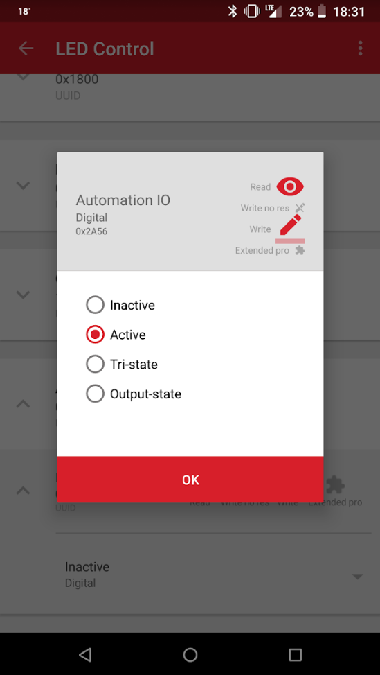
Traverse to the Automation IO service / Digital characteristic.
Change the state from Inactive to Active. You should see LED0 turning on.


According to the GATT specification, the Digital characteristic has 4 states (stored on 2 bits):
0x00: inactive
0x01: active
0x02: tri-state
0x03: output-state
Try "tri-state" and "output-state" as well. You will see LED1 turning on if you apply "tri-state" and both LEDs turning on if you apply "output-state", which happens because LED0 is driven by the 0th bit of the characteristic and LED1 is driven by the 1st bit.
