Implementing Wireless Direct Test Mode (DTM)#
Introduction#
Designing an embedded system correctly is a complex task. As a result, radio testing is a critical step that any design cycle needs to implement.
Because it is wireless, a Bluetooth-based design might need to support wireless-based testing method because some devices can be fully enclosed, preventing any physical access via wired protocols such as UART.
The Direct Test Mode (DTM) routines are part of the BGAPI and consist of two commands that can be used to test transmission/reception of your design. The most common way to use them is having a device programmed with Network Co-Processor (NCP) firmware and launching the commands from a host using BGAPI over UART. For more information about DTM and radio testing, see AN1046: Bluetooth® Radio Frequency Physical Layer Evaluation
The purpose of this document is to enable using DTM routines completely wirelessly (no physical access to the device required) and describe a wireless testing implementation. This example also explains how to integrate that feature into you design using the WSTK + radio board as an example.
Prerequisites#
To test the wireless testing solution, you need two WSTKs, one as the radio transmitter and another as the radio receiver. You will additionally need a third to device to configure the test parameters on the transmitter/receiver. A smartphone with EFR Connect app (Apple Store, Play Store) is enough for this purpose.
Note: "direct test mode" is part of the Bluetooth standard
Background#
The Devices Under Test (DUTs) are slave devices which can be used either as transmitters or as receivers. You can use a single master device to control both DUTs or separate masters, one for each device.
The receiver portion of the test is triggered by a call to the following routine (see detailed command description in the Bluetooth API):
gecko_cmd_test_dtm_rx(uint8 channel, uint8 phy);The transmitter portion of the test is triggered using the following routine (see detailed command description in the Bluetooth API):
gecko_cmd_test_dtm_tx(uint8 packet_type, uint8 length, uint8 channel, uint8 phy);This example allows passing the arguments to the DUT over the air, through a custom GATT service for each of the commands, and trigger the test commands on both the receiver and the transmitter. Furthermore, it allows reading the number of packets received/sent after the test is completed on both TX/RX DUTs.
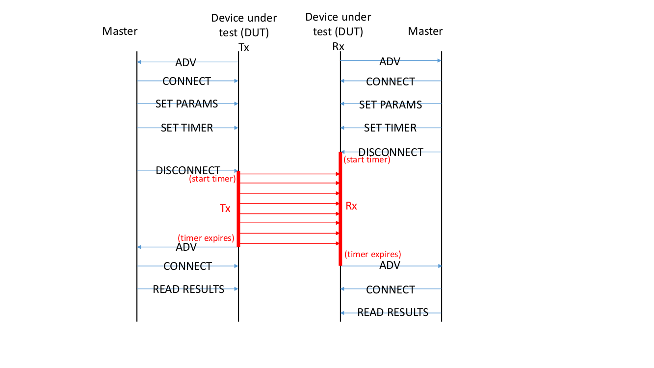
The following charts indicate the sequence of steps allowing the master to control the two devices. Typically, one is the transmitter and the other the receiver. The master (acting as a GATT client) will send the arguments of the gecko_cmd_test_dtm_rx and gecko_cmd_test_dtm_tx routines respectively to the receiver and the transmitter. In addition, it will also pass a time argument which is the duration of the test. To ensure that packets are not lost by the receiver, the receiver should be started first and stay in RX test mode for a longer period than the transmitting device so that all packets are captured.
Receiver:


Transmitter:


Transactions flow:


To ensure successful operations shown in the images above, the tester needs the corresponding Bluetooth services and characteristics in the GATT editor.
Description#
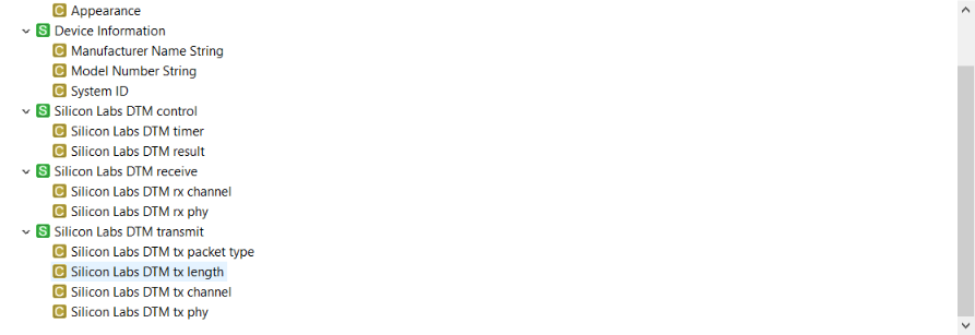
The GATT database consist of the RX routine and TX routine service, as well as a control service. To pass the arguments in this example, one characteristic is used for each so that it is easier to use and understand.
The following is the layout of the GATT database in the GATT Configurator:


As shown in the above figure, a service is also needed to read back the result of the test and set the duration of the test (Silicon Labs DTM control service). The test duration parameter is required because both devices will drop any on-going connection with the master device before the test starts. It is not possible to have connections or any other Bluetooth activity while doing DTM test so that the radio is fully available for the testing procedures.
The control service is then defined that implements the following characteristics:
DTM timer: two bytes characteristic that implements the time which configures the test duration (in seconds).
DTM result: two bytes characteristic that allows the user to read the result from the previous test
After the timer has elapsed, the routine that ends the test is called and triggers the tester to re-advertise so the master can reconnect and read the result from both TX and RX DUTs.
Because the code is readily available, it is not discussed in detail in this example. However, the following is a high-level state machine that explains how the tester works from the perspective of the RX/TX DUT.


Setting up#
First, you need to create the soc-empty for the specific radio board that you are using with SDK 2.12 or above.
Overwrite app.c with the file at the end of this example.
Import gatt.xml to the GATT configurator and generate the new gatt_db.h and .c files.
At this stage, the project should be compiling. Update both the receiver kit and the transmitter kit with the newly compiled image.
Usage#
Power up the receiver kit.
Connect to device called dtm_test via Bluetooth using whatever phone application or program you prefer.
Write in the timer characteristic the timer value on the receiver, in seconds. This tells the receive how long it must be in RX mode (this mode is entered once the master drops the connection).
Write the two arguments for gecko_cmd_test_dtm_rx via the characteristics in the DTM receive GATT service.
Power up the transmitter kit.
Connect to the second device that advertise using the same name dtm_test via Bluetooth (using a second phone for example if needed). You can also change the device name to more easily distinguish between RX and TX DUT.
Write in the timer characteristic the timer value on the transmitter, in seconds. This tells the transmitter how long it must be in TXmode (this mode is entered once the master drops the connection).
Write the four arguments for gecko_cmd_test_dtm_tx via the characteristics in the DTM transmit GATT service.
Disconnect the master device from the receiver first (that will trigger the receiver to start RX test mode).
Only after, disconnect the master device from the transmitter (that will trigger the transmitter to start TX test mode).
Test is running until the configured test duration time expires.
After the test has finished on both testers (transmitter and receiver) are re-advertising.
Reconnect and read out the result. The result corresponds to the number of packets received (if the result is read on the receiver) and the number of packets transmitted (if the result is read on the transmitter).
