Adding Bluetooth and Platform Components in Simplicity Studio v5#
Introduction#
Simplicity Studio v5 (SSv5) introduces change in development aspects, such as project creation, configuration tools, code structure, and so on. This lab focuses on getting started with Bluetooth using SSv5 by building a basic example and extending the capabilities of the projects by adding iBeacon, LED, and button components using the Project Configurator and component editor tools.
This guide is designed for developers who are new to Simplicity Studio v5 and the Silicon Labs development hardware. It provides instructions to get started using the example applications provided with the Gecko v3 SDK (GSDK).
Topics covered#
Using the new GATT configurator
Adding components and learning how to add them to a project
Learn how created projects can be interfaced to EFR Connect, the latest Bluetooth Mobile App from Silicon Labs
Getting Started#
Review the following material before starting the Bluetooth 5 labs. Ensure that you have the correct hardware and software to successfully complete the labs.
Hardware Requirements#
Silicon Labs Thunderboard BG22 Kit: SLTB010A
EFR32BG22 Soc
Software Requirements#
Simplicity Studio v5
Gecko SDK v3.0 with the Bluetooth stack installed
EFRConnect Mobile App
Install Tools#
Download and install Simplicity Studio 5 if it is not already installed.
Connect your Hardware#
Attach the development kit assembly to the PC with Simplicity Studio installed by using a micro USB cable (not a charging cable) and connecting between the PC host USB port to the J-link USB port on the kit.
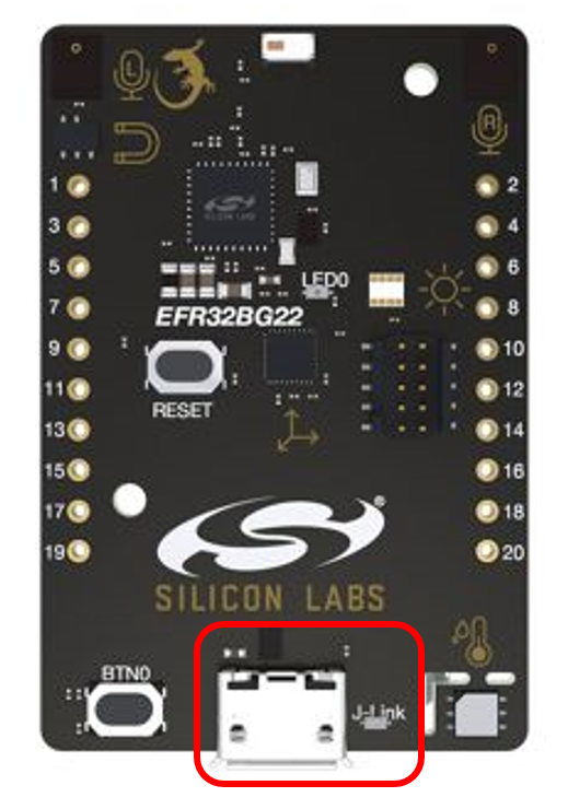

Note: By having the hardware connected via the USB debug connector when Simplicity Studio installs, Simplicity Studio will automatically obtain the relevant additional resources it needs to identify the kit.
Lab 1: Getting Started with SoC_Empty Application#
In these instructions you will compile and load the example application, SoC_Empty, to create a simple project that includes the Bluetooth stack using the latest SSv5 GSDK. The SoC_Empty project is a great starting point for new application development. The SSv5 version of the project has the same functionality as the SoC_Empty example application from previous versions of Simplicity Studio and can be used to advertise and connect to a mobile application, such as EFR Connect. When working with example applications in Simplicity Studio, you will execute the following steps:
Select the SoC_Empty example application
Compile and flash the application to the BG22 board
Interact with the application using the debugger. These steps are described in detail in the following sections.
Selecting the SoC_Empty Example Application#
When opening SSv5 for the first time you should be taken to the Launcher perspective. From this perspective you will see several different tiles with information about the target SoC as well as the target hardware being used.
If the Thunderboard BG22 Kit has not been plugged in using the USB cable, do so now. The kit and debug information should be displayed in the Debug Adapters window.
In the “Debug Adapters” window click the Thunderboard debug adapter.
If SSv5 has not started in the Launcher perspective, click the “Launcher” button in the top right of the main window.
From the Launcher perspective you see a lot of information about the target hardware and software that will be used when generating new projects or building existing projects. This view is different than the view is SSv4. Take a look around and the layout and what is available on this view with the different tiles.
Be sure the “Gecko SDK Suite v3.0.0” or later is slected as the “Preferred SDK.”
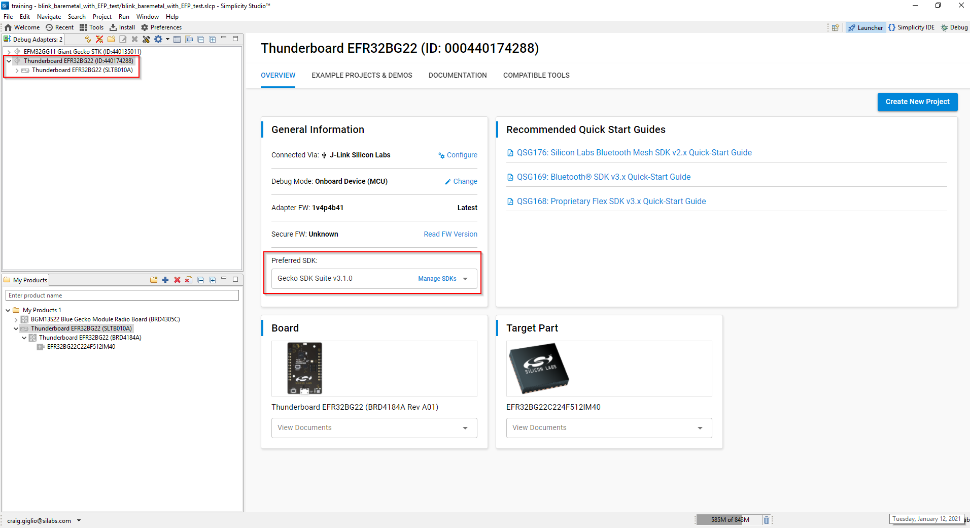

Select the “Example Projects and Demos” tab to provide a list of the projects available for the target hardware selected.
Scroll down to the “SOC - Empty” project and select “Create.”
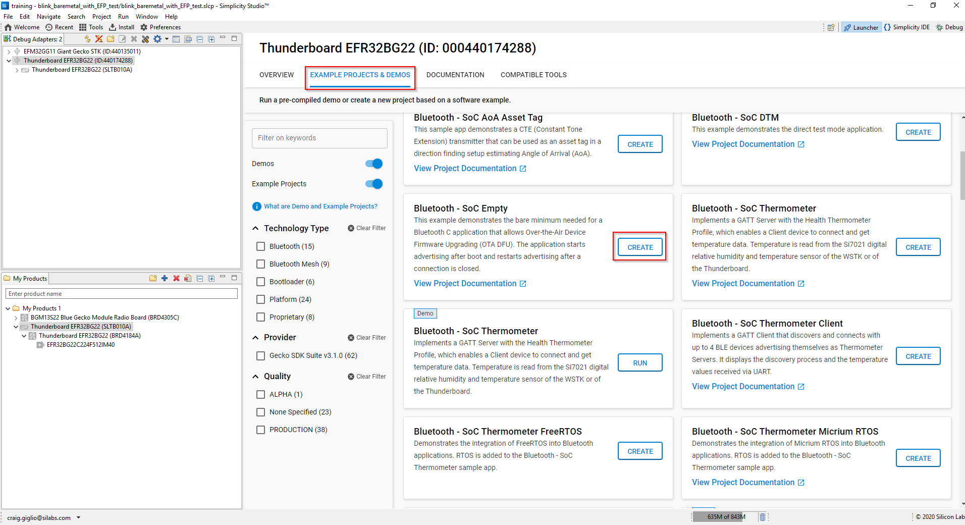

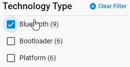
Note: You can select the filters on the left to reduce the number of elements shown to simplify finding the desired project.

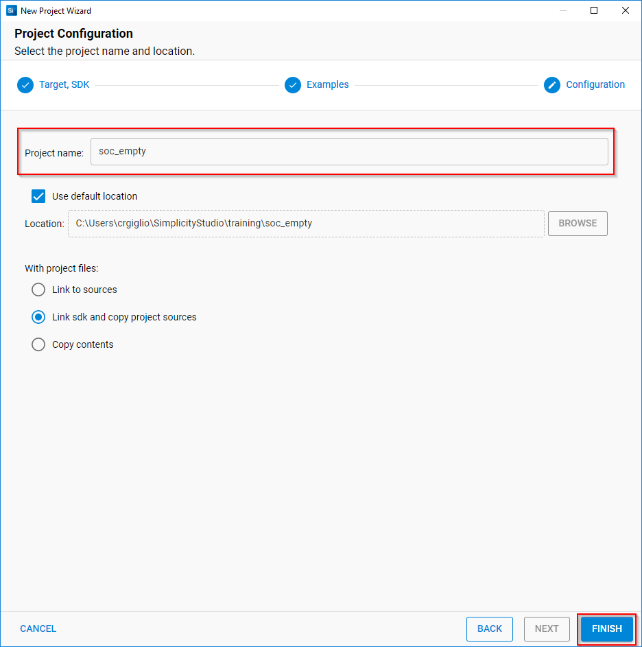
Enter the name of the project you want to create. The example used for this example was left as the default “soc_empty.”
Click “Finish” to create the new project.

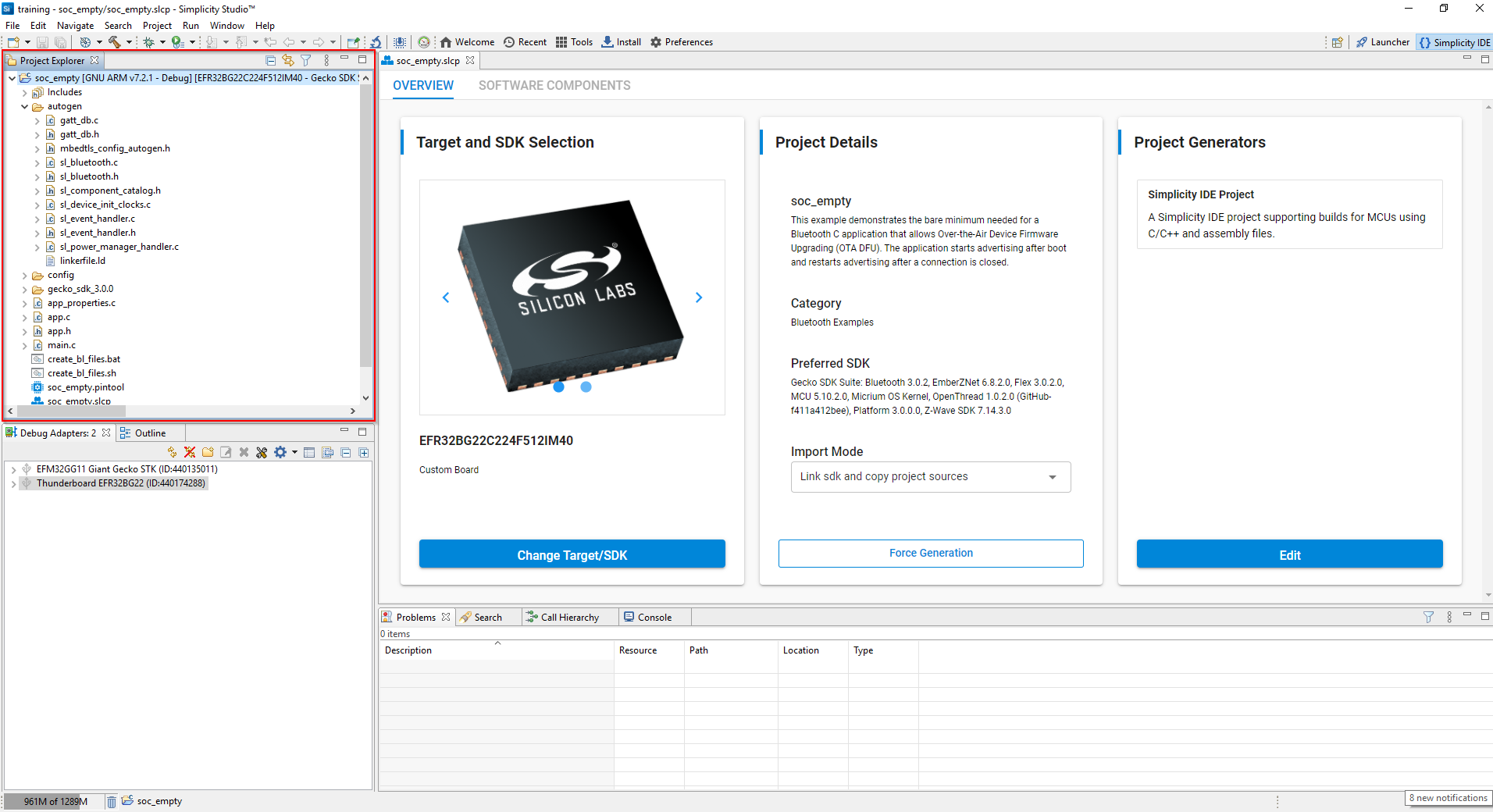
Once the project is created SSv5 takes you to the “Simplicity Studio” perspective. From the “Project Explorer” window you can see the project files that have been generated. The project structure follows the same format that was adopted in SSv4 with the main.c and app.c/h files.
Note the “autogen” folder that contains all of the files that are automatically created by the SSv5 tools. The files within this folder automatically get updated when you add or delete items from the project. This is different from SSv4 where the user had to “generate” after changes were made.

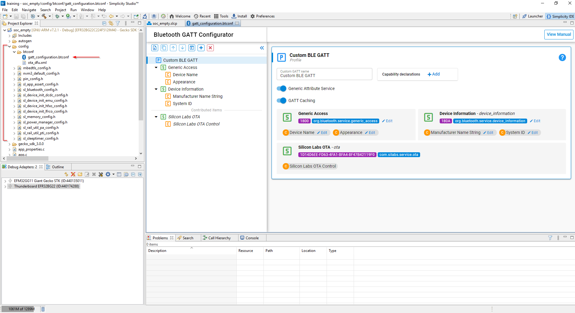
The GATT configuration is now located under the “config” folder in the project. Click the “gatt_configuration.btconf” file under the “btconf” folder.

Take a moment to review the fields in the “Bluetooth GATT Configurator.” Within this tool, the Bluetooth service and characteristic parameters can be added, removed, edited, and so on. The default services and characteristics for the soc_empty project are shown in the figure below. The Bluetooth parameters are shown logically in a folder type view as well as a window to enable editing the configuration.
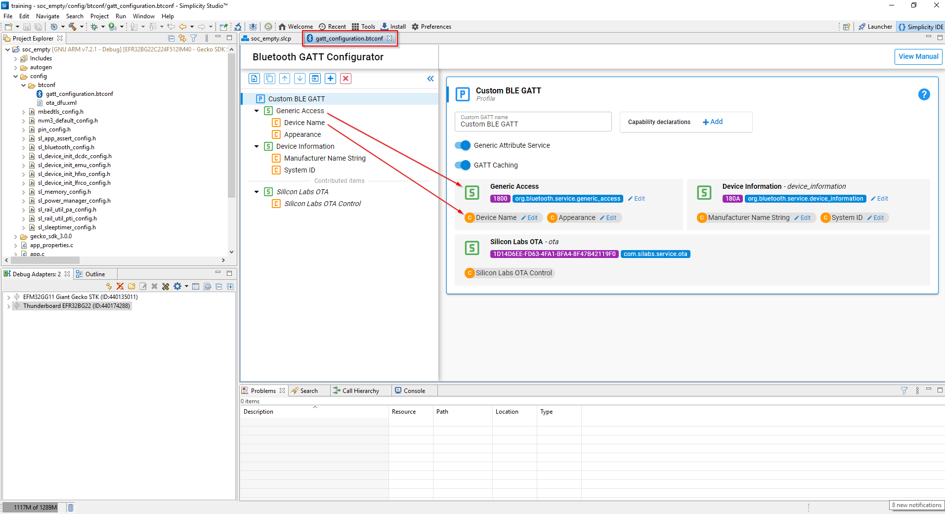

Click the ”Edit” button of the “Device Name” characteristic found within the “Generic Access” service.


Enter a new device name so that it is identifiable from other devices within range of the mobile device that will be used. In the example below, the new name given was “Lab1 SoC Empty.”
Note that the “Value Length” of the name must match what was entered. The original “Empty Example” name has 13 bytes. If the length does not match, the configurator will flag the issue and highlight it as shown in the pop-out figure.
Enter the correct number of bytes in the new name entered. "Lab1 SoC Empty" has 14 bytes as shown.
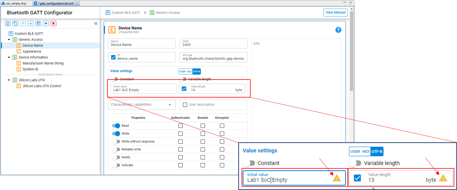

Note The tools will autogenerate many of the files and configuration parameters when changes are made. In the lower right corner of the IDE there is a progress bar to show when tools such as the indexer, or other autgenerators are active.
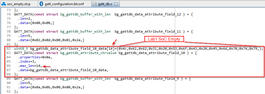
Note that the changes made to the Device Name and the variable length field are automatically updated in the autogenerated files when the btconf file is saved. To verify, open the gatt_db.c file and navigate to the bg_gattdb_data_attribute_field_10_data[] parameter and note the variable length and the Device Name entered (the Device Name is in hex).

Build the project by clicking the hammer toolbar button.
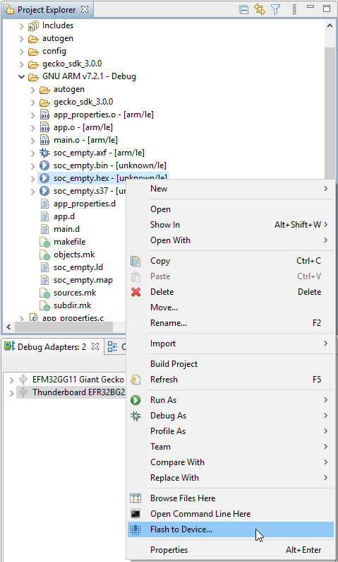
Once built, flash the generated hex file to the target by right clicking the "project name.hex" file in the “GNU ARM v7.2.1 – Debug” folder.
Note The GNU ARM v7.2.1 – Debug folder contains many of the output files from the build such as .map files. You can access them from the Project Explorer window. The "Binaries" folder also has the build output files that can be used to download to the target.
Select “Flash to Device…”

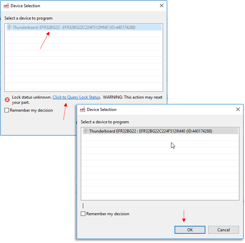
The BG22 has additional security features and in some cases (i.e., when the board is first plugged in), the tools will prompt to query the Debug Challenge Interface (DCI). Select the connected device and then the link for “Click to Query Lock Status.” The device target to program text will no longer be grayed out and then select “OK.”

The Flash Programmer will open. Click “Program” to download the code to the target.
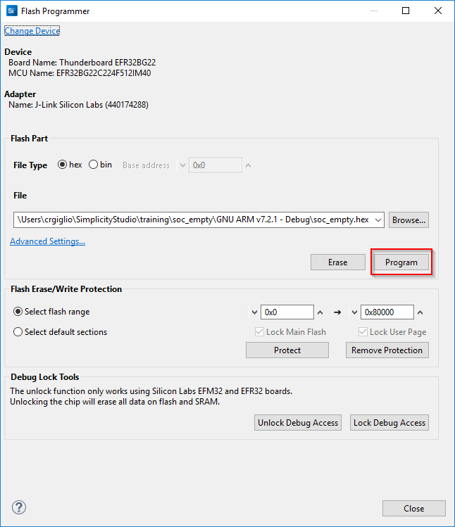

Note: There may be times where the specific debug adapter needs to be selected. If prompted select the TB BG22 kit.
Open the mobile app “EFR Connect” and select the “Browser.”
The newly downloaded SoC_Empty application should be issuing Bluetooth advertisements. Start scanning in the mobile application If you cannot see the advertising packets.
Since there are so many Bluetooth devices broadcasting at any given time, try using the filter settings in the app to isolate the app flashed to the board.
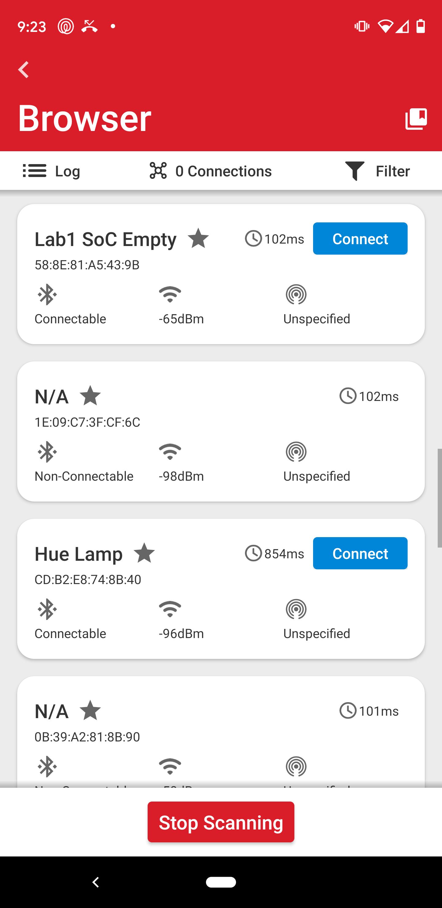

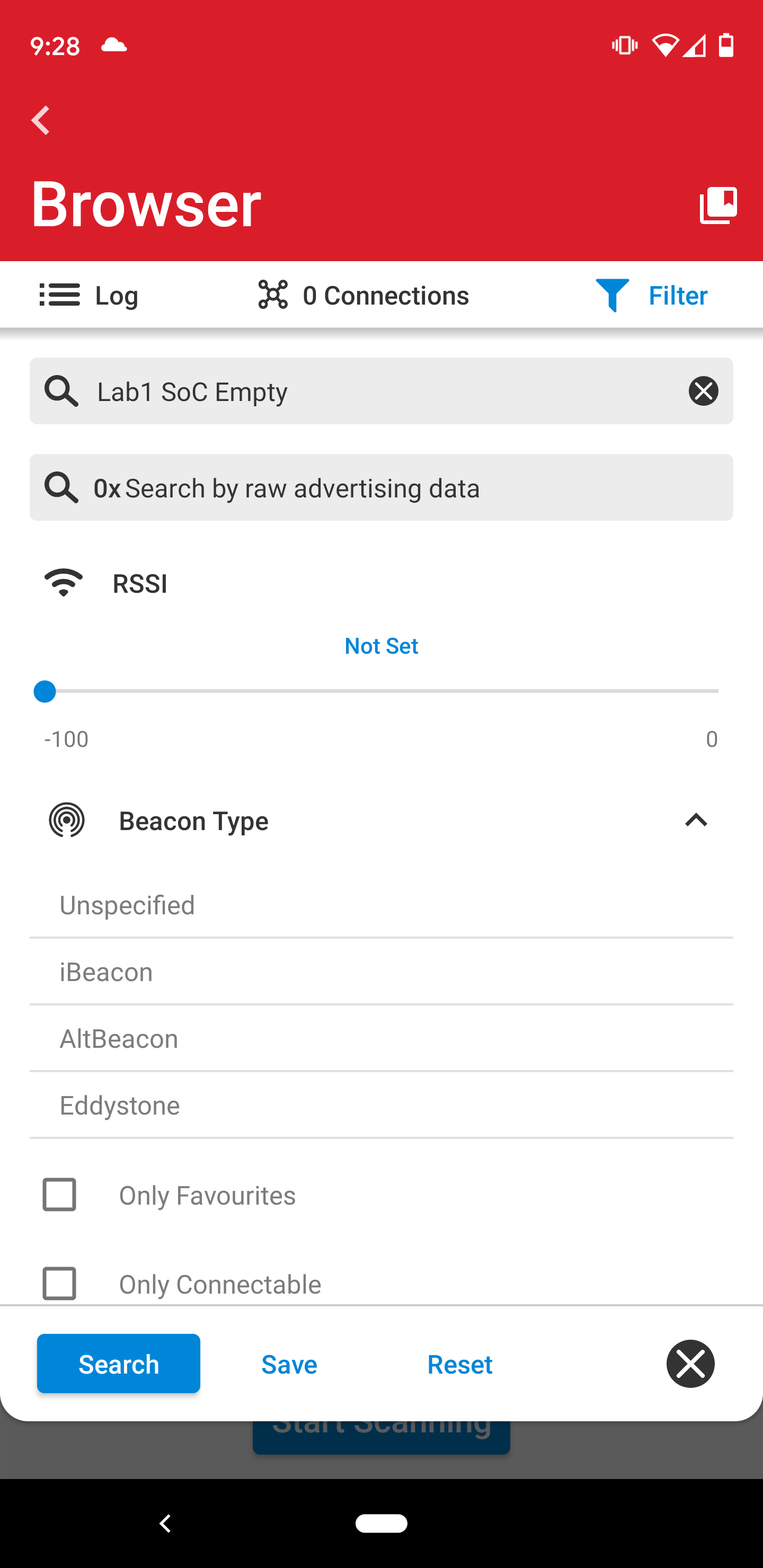

Note: If the board is not found, press the reset button on the BG22 or restart scanning in the app. In some cases, the bootloader may be missing from the device if it has been completely erased. If that happens, open the Flash Programmer and program the bootloader found here:
C:\SiliconLabs\SimplicityStudio_v5\developer\sdks\gecko_sdk_suite\v3.0\platform\bootloader\sample-apps\bootloader-storage-internal-single-512k\efr32mg22c224f512im40-brd4182a\bootloader-storage-internal-single-512k.s37
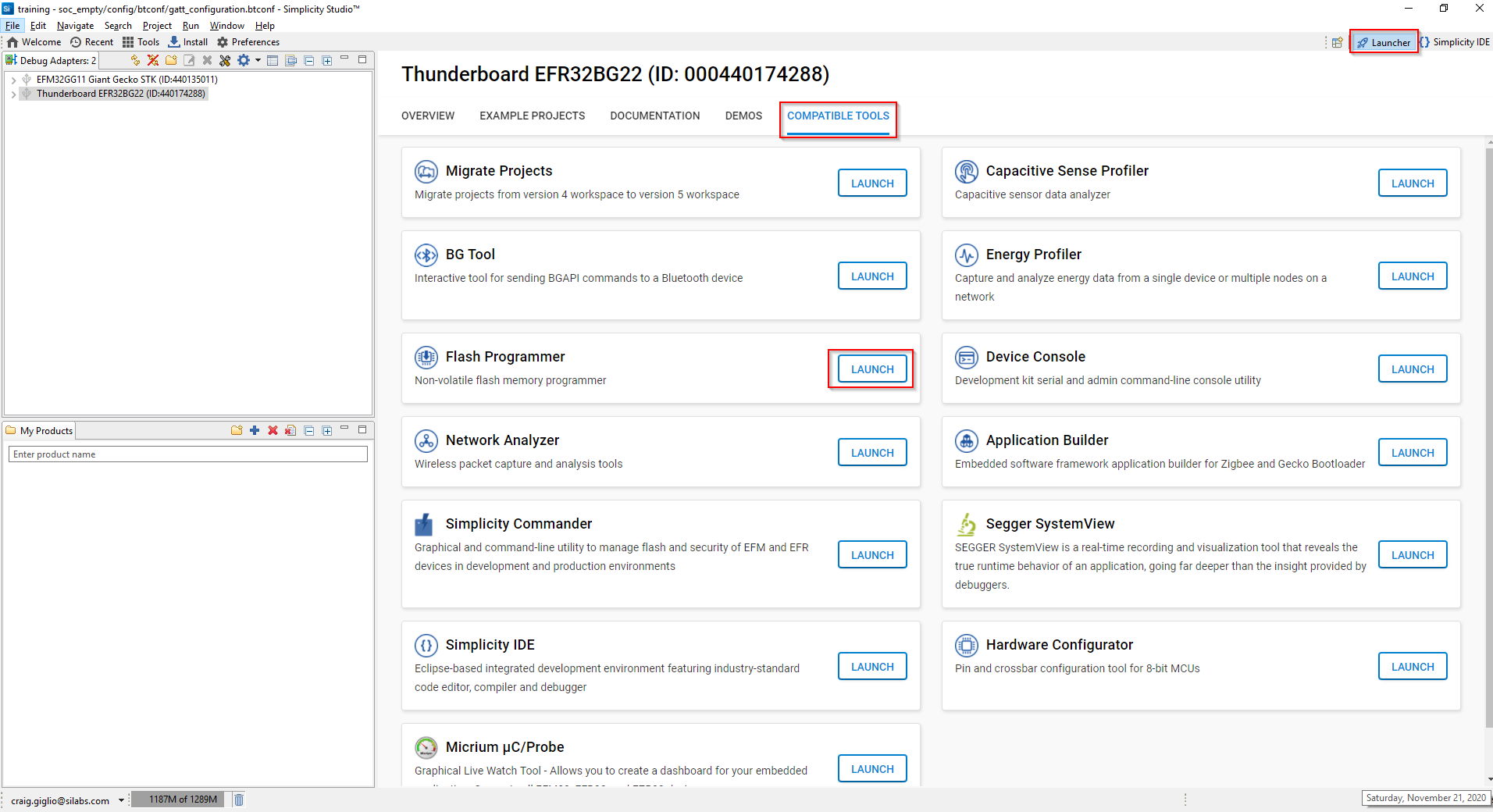
In the earlier steps the "Flash Programmer" was launched from the Project Explorer window. If the bootloader needs to be updated you can open the "FLash Programmer" from the Compatible Tools tab from the "Launcher" perpective.

Recap of the SoC_Empty Example Application#
Congratulations, Lab 1 demonstrated many new features of SSv5, compared them to SSv4, and covered these topics:
Creating a new project
Using the GATT configurator to edit characteristics
Viewing autogenerated files
Build and download an application to a target
Introduced EFR Connect mobile app
Lab 2: Turn SoC_Empty into an iBeacon using Project Configurator#
The GSDK v3.0 project framework has been developed to seamlessly add and remove functionality to applications using “components.” The new Project Configurator tool simplifies adding/removing functionality to applications by “installing/uninstalling” software components. This lab will use the iBeacon component to highlight the Project Configurator ease of use. iBeacons are a type of advertising packet defined by Apple to facilitate a simple form of Bluetooth tracking using advertising packets and RSSI. This lab will build on the soc_empty project created in the previous lab.
Using the Project Configurator#
From the “Simplicity IDE” perspective, select the “SOFTWARE COMPONENTS” tab in the component configurator view. The window may be open by default, but if it is not shown with the current set of tabs it can be opened by selecting the "project name.slcp" file from the Project Explorer window.
Note: Project Configurator project description files describe a single software application, from which an IDE project can be generated. A project description file will have the *.slcp extension. The project has a list of components. Each of these components can require certain features. Other components can provide these features and they will be included during the project generation process. These components can require other features. The project generation process should make sure that all feature requirements are fulfilled.
Navigate to the Bluetooth configurations and select “Application.”
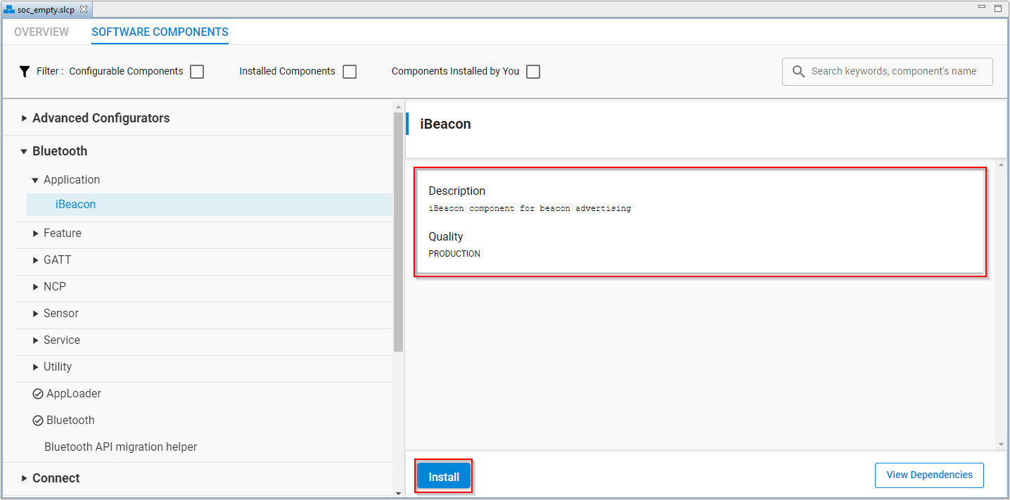
At this point, the iBeacon component should be displayed. Select the “iBeacon” component. Notice the details that are shown for the component such as Description and software quality level. In this case, the iBeacon is PRODUCTION quality.
Click the “Install” button.

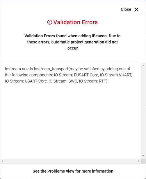
In some cases, there may be dependencies on the recently installed component. If that happens, you will get an error message with a list of links to add components that may satisfy the dependencies. If none of the components listed are the ones you want to use, you can close the error window and choose a different component. For the iBeacon component, an “iostream” component is required. We are going to close the Validation Errors window and choose a different component than the options provided.

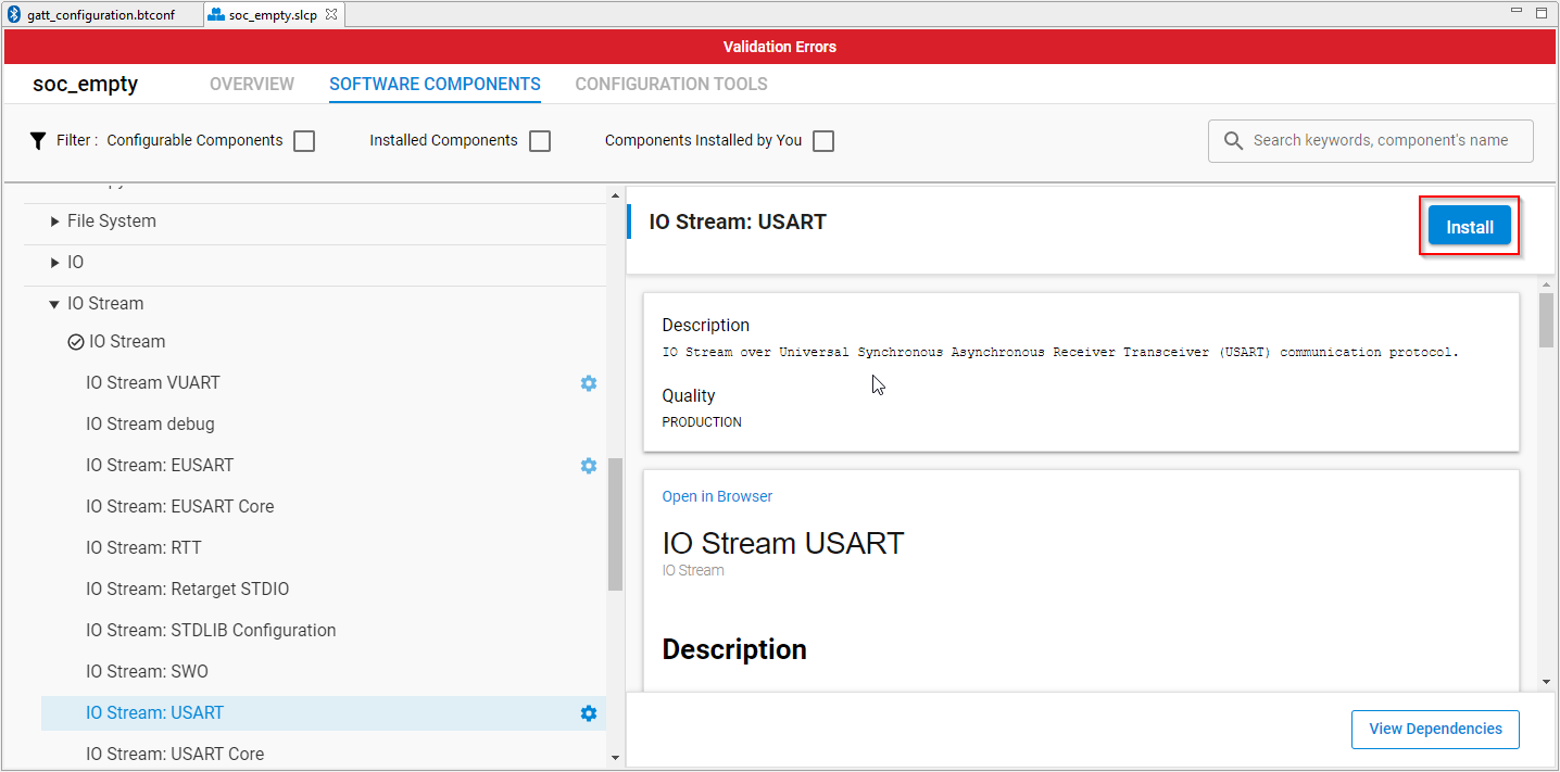
Navigate to the iostream components by following the path listed below and install the “IO Stream: USART” component.

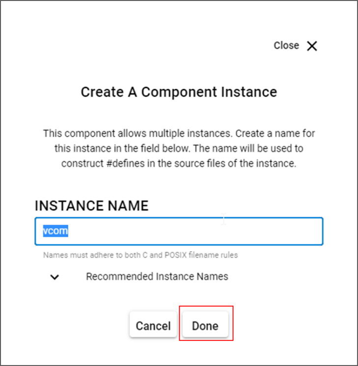
A component instance will be created. A default instance name, in this case "vcom", will be populated in the “INSTANCE NAME” field, which is used to identify the component in the code. Select “Done” to complete adding the iBeacon component.

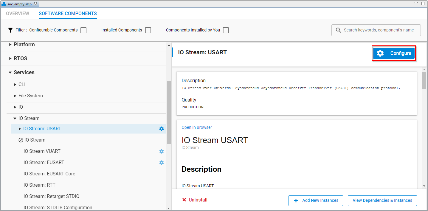
The IO Stream component will need to be configured. Select "Configure" to open to component editor.

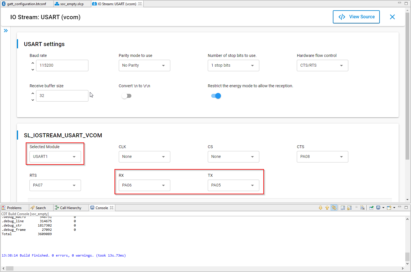
The default io stream module is set to USART1.
Since we are using one of the development kits, the default pin configurations should align with the settings of the target hardware. On the TB22 board, the USART1 pins are routed to ports PA05 (TX) and PA06 (RX). If using a custom board you may have to change these configurations to match the hardware.

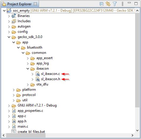
Look at the project structure in the Project Explorer window. There should be iBeacon related code added to the project. Check the gecko_sdk_3.0.0\app\bluetooth\common\ibeacon folder for new component files.

The code in the iBeacon.c file starts an iBeacon advertising instance with the iBeacon defined advertising packet data. By adding the iBeacon component, an existing SoC_Empty advertiser in the system_boot_id and the iBeacon instance in iBeacon.c advertiser instances are created. When adding the iBeacon component, the existing code for the default advertiser is not removed. As a result, the device advertises both as the original Empty Example and as the iBeacon. To have only the iBeacon, remove all the code in the sl_bt_evt_system_boot_id event in the app.c file. When done the event id for the system boot should look as follows:
case sl_bt_evt_system_boot_id:

break;
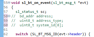
There will be warnings about unused variables now that the code in the boot event has been removed. They do not affect the code operation. To remove the warnings, however, comment out the variable declarations shown below.

Rebuild and download the code to the BG22 target. The BG22 should now be advertising as an iBeacon. The iBeacon can be verified by reviewing the advertising packets in EFR Connect.
Within the Browser under the Filter view select “iBeacon.”
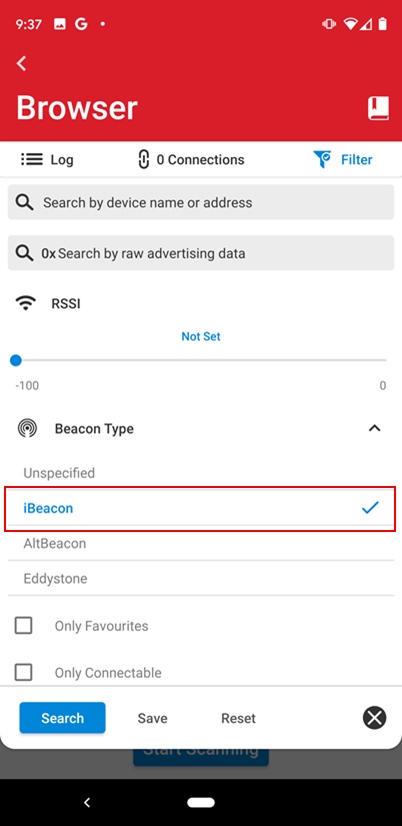

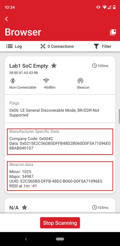
Once filtered look for the Device Name entered in Lab 1 and select it to review the parameters associated with the advertising data. As mentioned earlier, Apple has defined a specific set of data to identify an advertising packet as an iBeacon. Look at the “Manufacturer Specific Data” field for the Company Code 0x004C which identifies Apple. There should also be an iBeacon data section that shows the remaining data for Minor, Major and UUID of the packet.

Recap of components using iBeacon#
Congratulations! Lab 2 demonstrated how to add a SSv5 iBeacon component to a project and covered the following items:
Using the Project Configurator
Add new components to a project
Component dependencies
Viewing autogenerated files
Build and download an application to a target
Lab 3: Enhancing an Application Using Custom Services and Components#
Lab 2 highlighted how simple adding code to an application can be using components by adding the iBeacon component. Lab 3 goes deeper into components by adding the LED component and showing how to use the generated code within the Bluetooth stack framework.

Add the Simple LED Component#
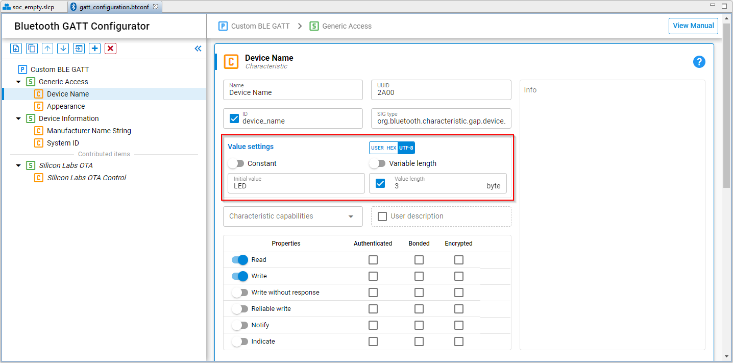
Create a new SoC_Empty project with the device name initial value changed to “LED.”
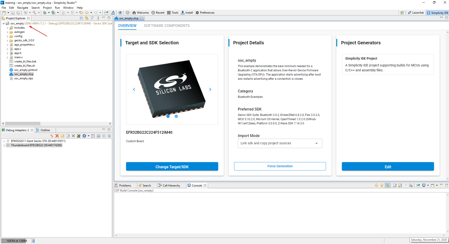


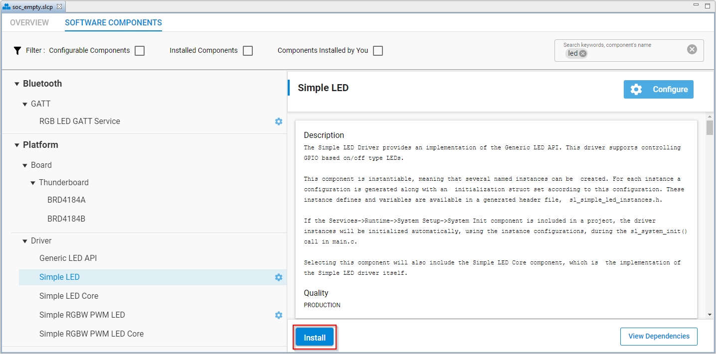
Using the Project Configurator tool, navigate to “Platform -> Driver” and select the “Simple LED” component. Like the iBeacon, the configuration tool provides a detailed description of the component. Select “Install” to add the component to the pro-ject.

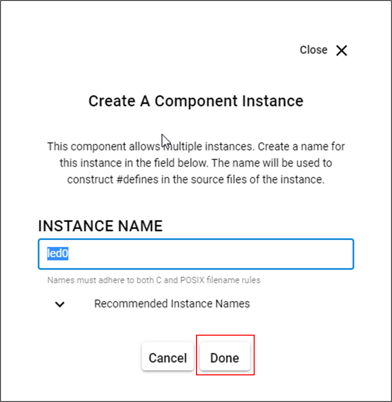
Each component requires an instance name. Each time a component is added a new instance name is provided by default. For the Simple LED, the default instance name is “led0.” This is the name that will be used when implementing the component in the code. Select “Done” to add the component to the project.

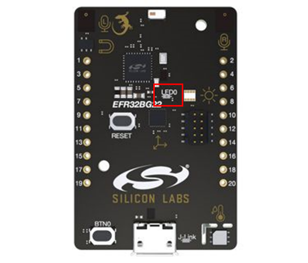
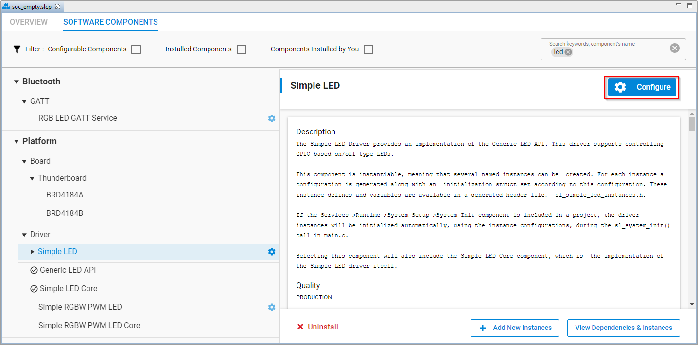
An LED is connected to the SoC via a GPIO pin. On the BG22 board, the LED is connected to GPIO port B pin 0. Select “Configure” to set the correct configuration.

The Simple LED (led0) configuration window is where the GPIO settings can be configured. There are other methods to set the correct GPIO, but we will use this method here.
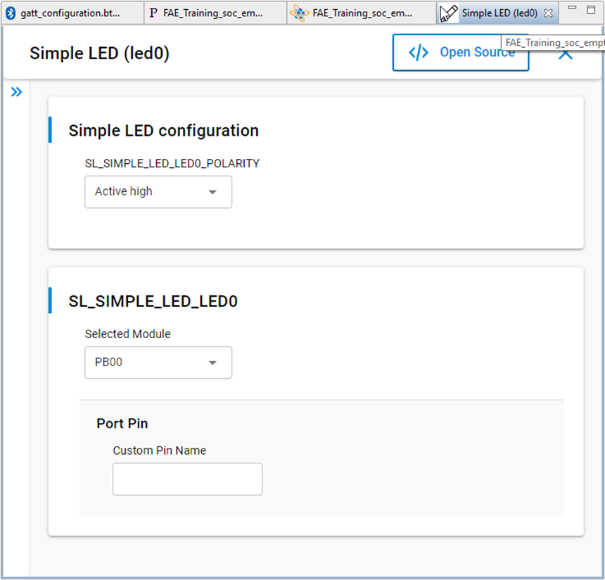

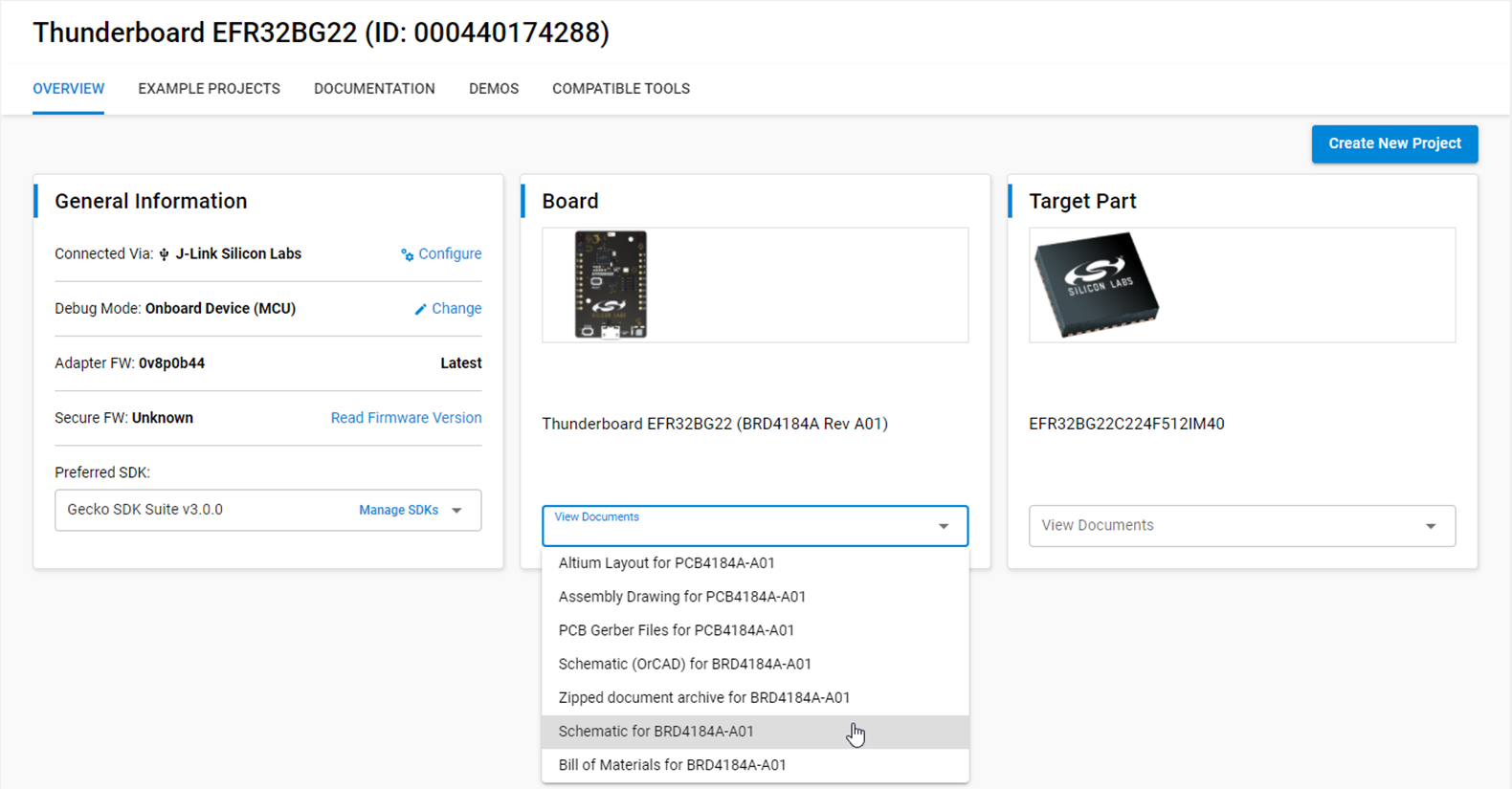
Note: Studio v5 has some very nice features regarding how it curates documentation and presents it to the user. To find out how the LED is connected to the SoC, from the “Launcher” perspective and under the “Board” card, select the “View Documents” dropdown and select the pdf version of the schematic.


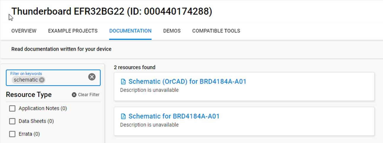
Another method to find documentation is to filter the search from the “Documentation” tab.

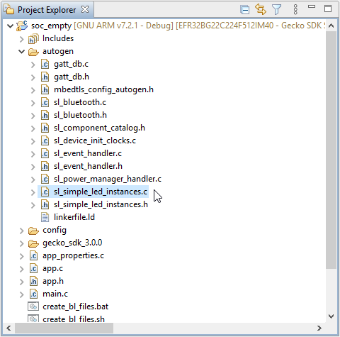
The component has now been added to the project. Take a look at the autogen folder in the Project Explorer window. The new component project files have been added automatically. This functionality of SSv5 is different than SSv4 where v4 required the project to be “generated” each time there was a change to the configuration.

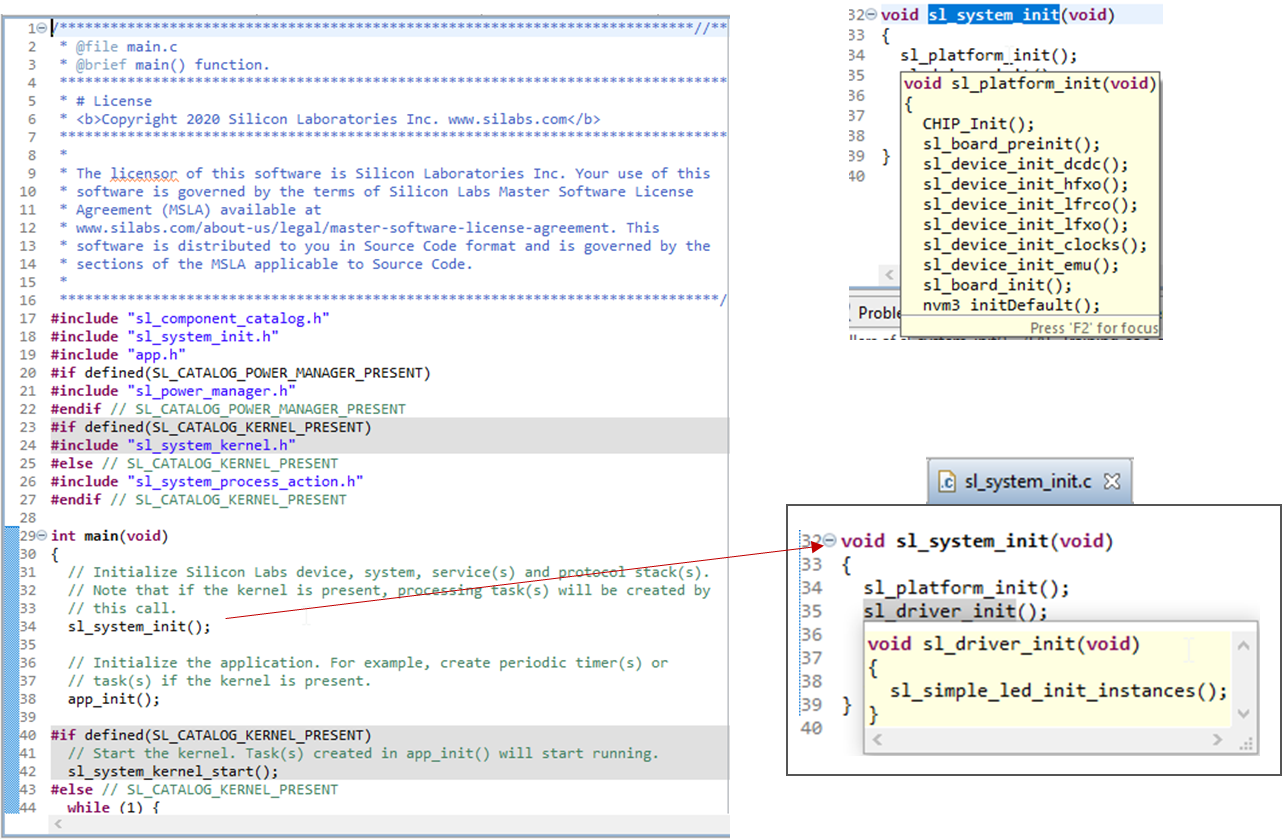
The next set of screen captures walk through the call hierarchy of the component initialization in the code. It may be difficult to follow, but the method used was to highlight the function and press “F3” or “Open Declaration” to trace through the function calls.
First is the sl_system_init function call in main.c. This starts the initialization for the system. Within the sl_system_init function is the call to the platform initialization. This function initializes all of the low level peripherals required by the SoC to run the application.
Another function called within sl_system_init is the sl_driver_init function. This function is the initialization for all of the components added to the application. In this case we see the LED driver initialization call here. As more components are added their initialization calls would show up here as well.

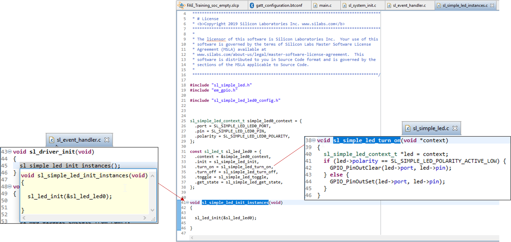
Continuing to trace through the function calls we get to the actual initialization of the component which is in the sl_simple_led_init_instances function. This is significant because this represents the underlying architecture of components and how they are constructed to seamlessly get added and removed from projects.
In the component instances file (found in sl_simple_led_instance.c) there are two structures defined: the context and component API structures.
The context structure identifies the resources consumed by the component. In the case of the LED it uses a GPIO which is composed of a port and a pin. In addition, the LED polarity is defined.
The second structure defined contains the handle to the LED context as well as a list of the APIs to support the component.
If we trace one of the functions in the API structure, we will see the low-level code that drives the LED.

Now that a new component has been added there will have to be a consumer added to the project. This will be accomplished by adding a custom service and characteristic to the Bluetooth application.
Open the GATT Configurator for the project and click the “Add New Item” button and select “New Service.”
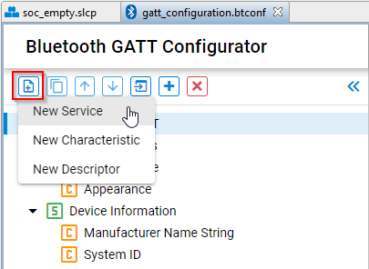

Highlight the new Custom Service and add a “New Characteristic.”
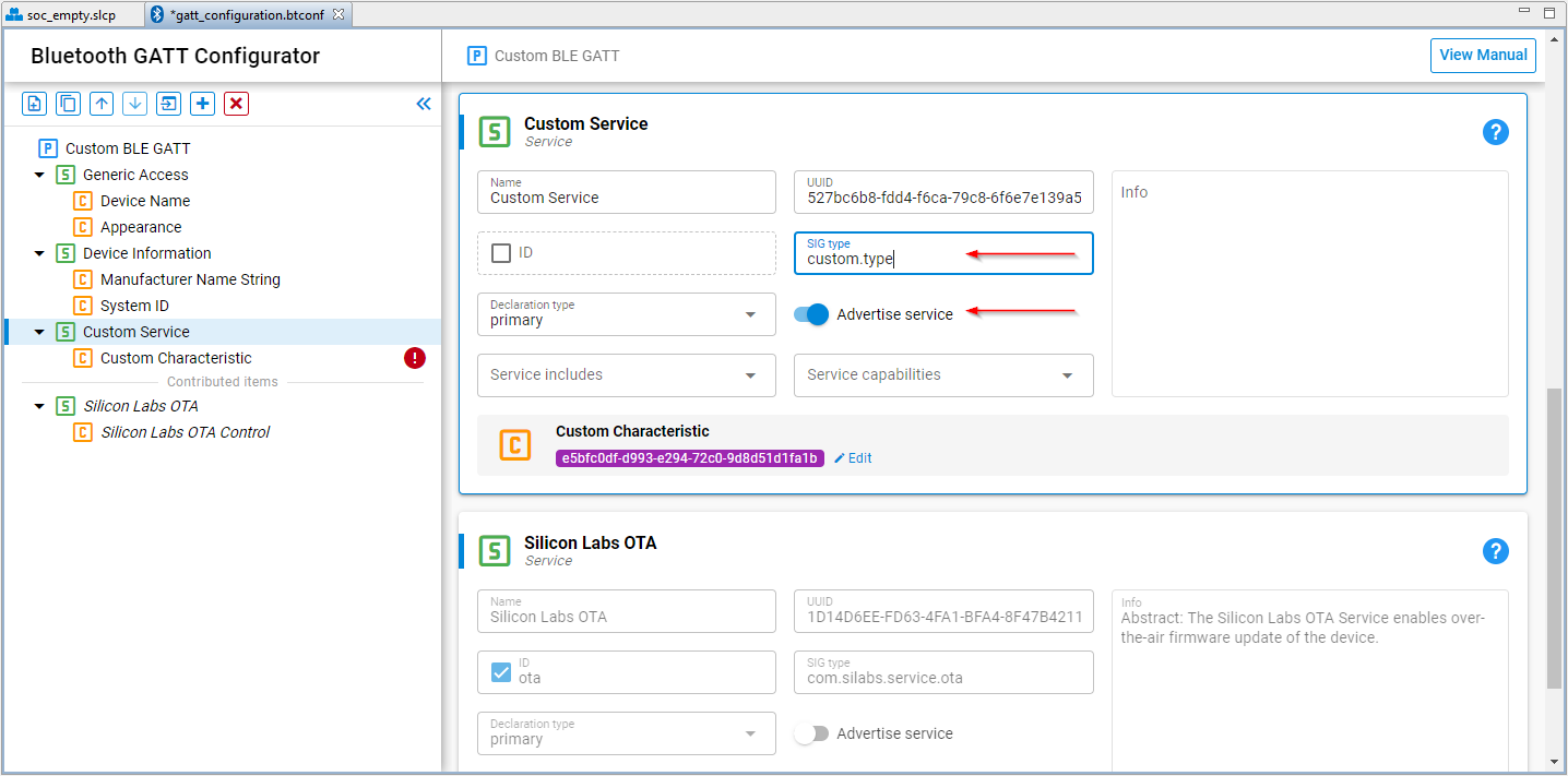
The new service will need to be discoverable. Select the “Advertise service” slider to enable advertising.
Click inside the SIG Type field and enter the type to be “custom.type.” (shown explicitly in this example)
Once both are added the configurator should look as follows:

The EFR Connect app will be used to turn the LED on and off. In order to do that we have to configure the characteristic for the custom service to be a “Write” with specific parameters. Click the Edit link in the “Custom Characteristic” to edit the characteristic parameters.


Use the parameters identified below to configure the characteristic. The Names and IDs can be changed to different names as well.
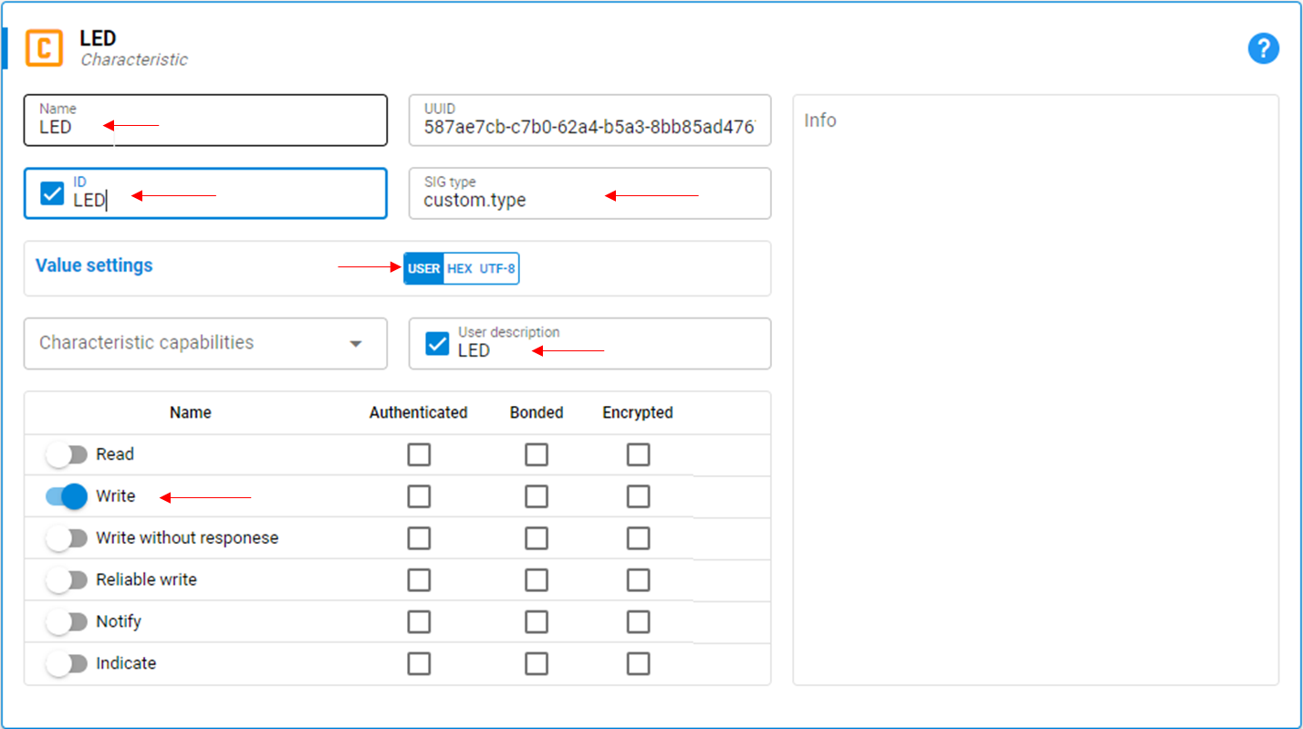

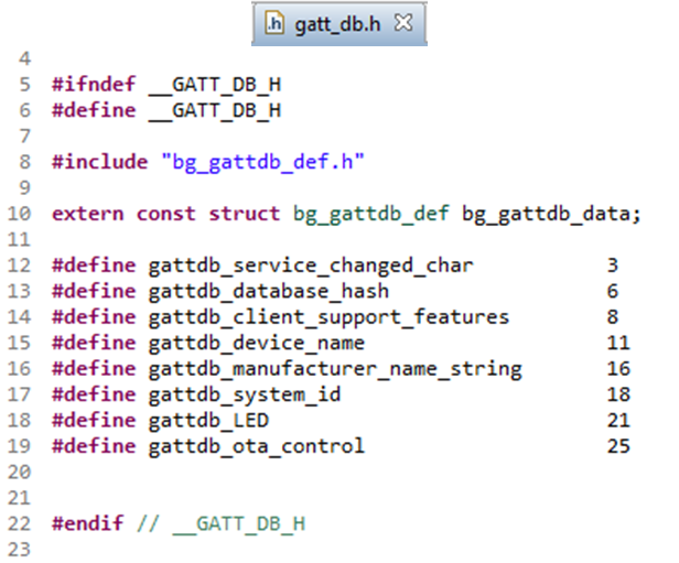
Once the changes are made and the file saved, the Bluetooth parameters will be added to the autogenerated source files. The Bluetooth stack uses handles for the characteristics defined. Open the gatt_db.h file and find the characteristic with the name provided in the previous step. In this case is was LED so the handle defined was gattdb_LED.

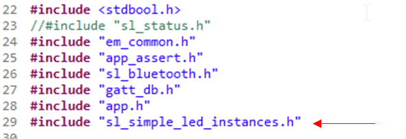
At this point the code generated from the component can be added to the Bluetooth stack framework to control the LED. But first the includes and variables must be declared. Open “app.c” and add the #include for the LED component instance header file.

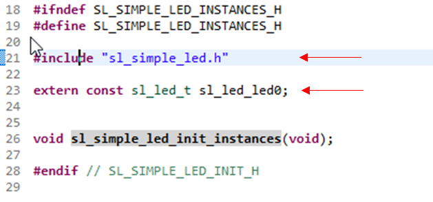
The instance header(sl_simple_led_instances.h) file includes the external definitions for the LED structure used to control the LED. There is no code modifications required for this step.

At this point we can add the code to the event framework of the Bluetooth stack. Recalling that the characteristic created was a write, the event handler for writes need to be added to the framework since SoC_Empty does not include this by default. In app.c, add the following code to the section identified by the comments to add additional event handlers.
The sl_bt_evt_gatt_server_user_write_request_id is used as the event for writes
The evt->data.evt_gatt_server_user_write_request.characteristic is the handle of the characteristic. In this case we de-fined the characteristic as gattdb_LED as shown earlier.
The attribute.value will be the data that is sent from EFR Connect.
And the use of the component resides in this event.
    ///////////////////////////////////////////////////////////////////////////
    // Add additional event handlers here as your application requires!      //
    ///////////////////////////////////////////////////////////////////////////
    case sl_bt_evt_gatt_server_user_write_request_id:
if (evt->data.evt_gatt_server_user_write_request.characteristic == gattdb_LED) {
        // Write user supplied value to LEDs.
          if (evt->data.evt_gatt_server_attribute_value.value.data[0]) {

              //This is the use of the Simple LED component
              sl_led_turn_on(&sl_led_led0);
          }
          else {
              //This is the use of the Simple LED component
              sl_led_turn_off(&sl_led_led0);
          }
        sl_bt_gatt_server_send_user_write_response(
            evt->data.evt_gatt_server_user_write_request.connection,
            gattdb_LED, SL_STATUS_OK);
      }
      break;
Looking at the code above, the GPIO initialization has already been completed as part of the autogen initialization functions. The APIs called were found in the sl_simple_led.c file.
Note: There are other ways to call the functions defined for the component using the declared context. The sl_led_led0.API references the APIs defined in the component instance file and uses the context already initialized as well. For example, the sl_led_led0.turn_on(&simple_led0_context) function can be used as an alternative method, but requires an extern variable declaration of the context..
Note: Remember the Instance Name that was used when generating the component? Note the use of the instance name in the API structure and the context of the component that was created. Some components can have multiple instances and this concept will be important when instantiating multiple instances of the same component.
Note: There have been changes to the APIs and event IDs when moving to GSDK v3.0 for Bluetooth. Note that the equivalent ID in v4 is different than what has been used here.
Build and download the application to the BG22 target (use the same steps 19 - 21 in Lab 1).
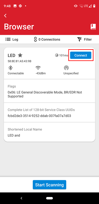
Using the EFR Connect app Browser, scan for the LED device and select “Connect.” If the "Initial value" for the "Device Name" characteristic was not changed in the first step the device may advertise with the "Empty Example" name.

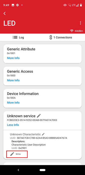
Click the Unknown Service and select the "Write” button.

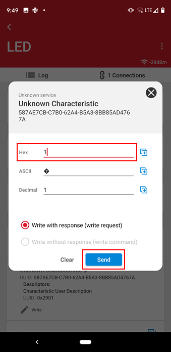
For this simple application the code will turn the LED on for a number > 0 and turn it off for a value = 0. Enter a “1” into the hex field and click Send. The LED should turn on.

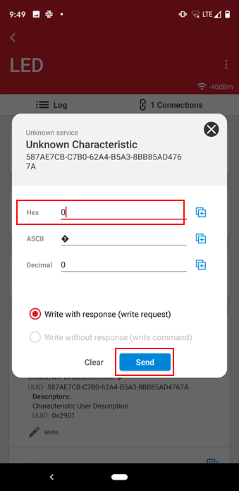
Select the Write button again and enter a value of “0” into the Hex field. The LED should turn off.

According to Lab 2, iBeacon_instance files should have been in the autogen folder.
iBeacon represents data defined by Apple for an advertising packet and was found in the GSDK platform code. The iBeacon component starts the advertising which requires no developer support. So, in that respect it is a little different than the LED component (and as you will see in Lab 4 the Button component). When you installed the iBeacon component the iBeacon.c/h files were added to the GSDK directories and not the autogen directories.
Adding and Using Custom Services/Characteristics and Components Summary#
Congratulations. Lab 3 demonstrated how to add a SSv5 component to a project and use the generated code to provide the functionality as well as adding a Bluetooth service to consume the component. The following topics were covered:
Using the Project Configurator to add and configure a component
Review the underlying generated component code framework
Viewing autogenerated files
Creating a custom service and characteristic
Adding a write event to the Bluetooth framework
Add code to use the component in an application
Use the EFR Connect mobile app to write data to a server device
Lab 4: A Deeper Dive into Components and Using Them with the Bluetooth Stack#
Many different Project Configurator components can be added to applications. Each one has a different level of complexity. In Lab 3, an LED was added to the project and it was an output only and controlled exclusively by the application. In some cases, components will make use of interrupts and other platform code such EMDRV to implement the complete functionality of the component. Lab 4 will add the button component. Although on the surface it sounds “simple” as the name implies, there are many considerations with adding a component such as this one.
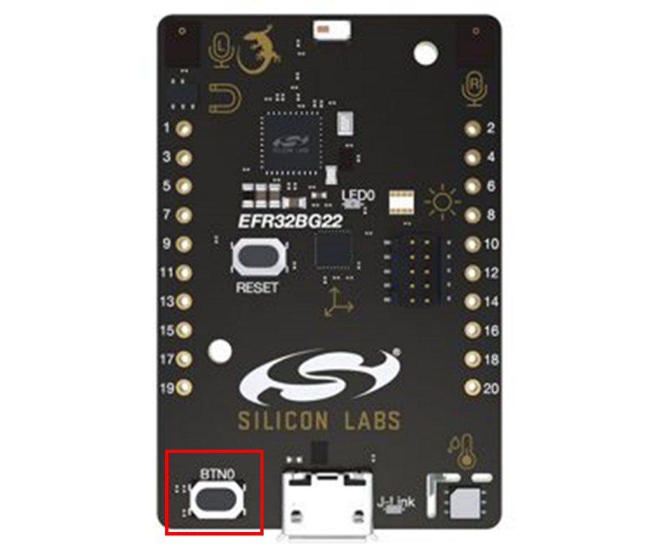

Add the Simple Button Component
This lab will build on the project created in lab 3. If you want to start fresh, create a new SoC_Empty project and bring it to the current state of the lab 3 project with one custom service and characteristic added for the write to the LED on the BG22 board.
Open the "project name.slcp" file.
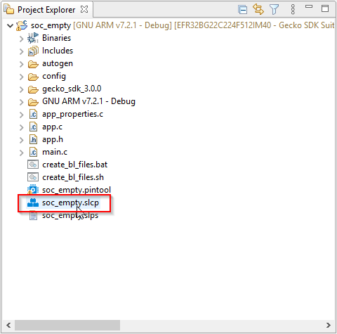

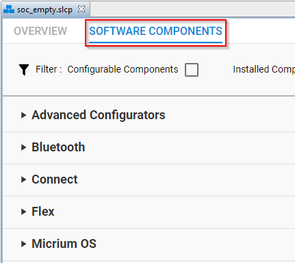
Select the “SOFTWARE COMPONENTS” tab to bring up the list of components available for installation.

Navigate to the “Simple Button” component (or enter "button" in the search) and click “Install.” Once installed, the source files will be automatically added to the project. No need to generate the project. Give the button an instance name of "btn0."
The button needs to be configured for the hardware. Select “Configure” to enable the configuration for the TB2 BG22 kit.
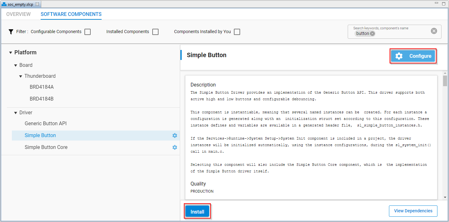


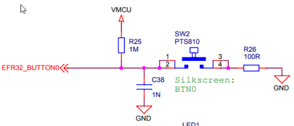


The button component has two options for retrieving the button state: polled and interrupt. For this lab, select the interrupt method for reading the button. Also choose the Selected Module to reflect the pin connections from the schematic: PB01.
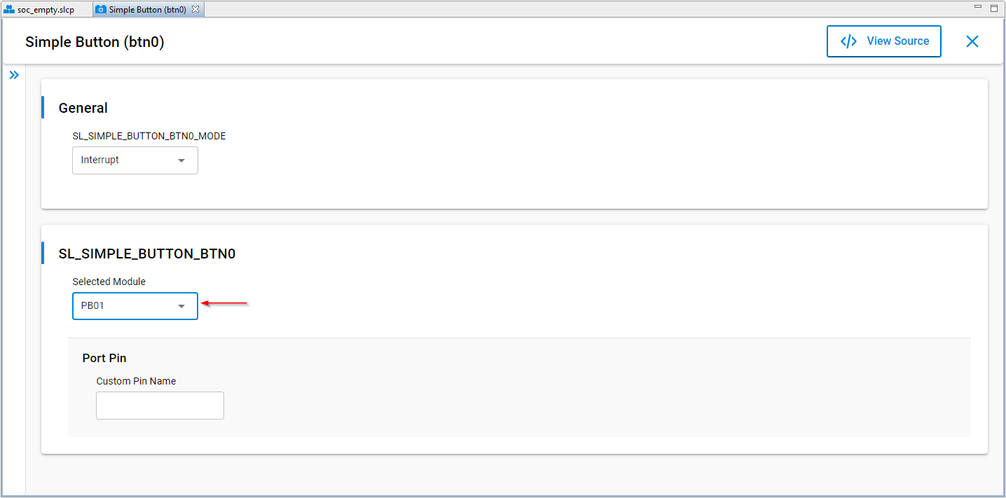

Once the parameters are set and the files have been automatically added to the project, take a look at the initialization functions similar to how the files were traced in lab 3. Notice that there are two functions in the driver initialization function, one for each component added to the application.


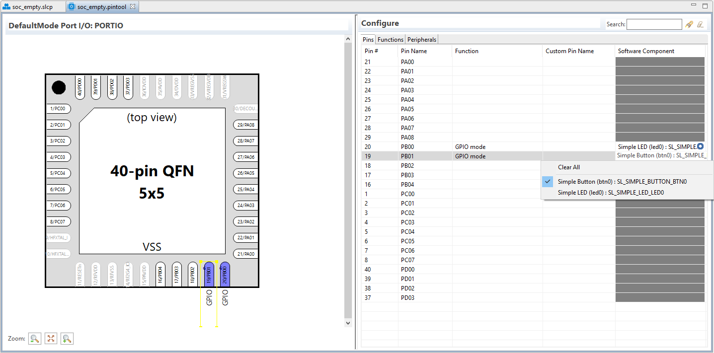
Note: There are other ways to configure the HW using the pin tool. The Project Configurator and pin tool are linked together so that changes to either tool will be reflected in the other.

Add the New Characteristic for the Button
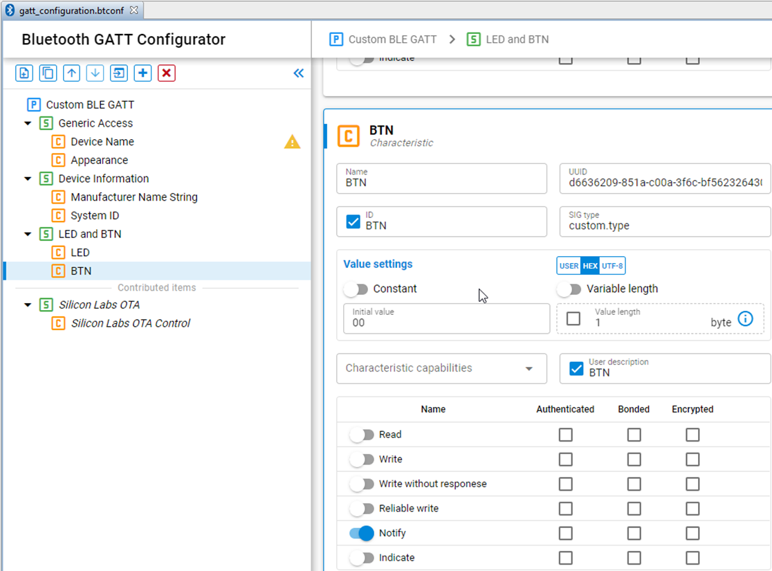
This example illustrates how to send the button data via a notification to the mobile app. Add a second characteristic to the Custom Service that was created in lab 3 (LED - steps 9 and 10). In this example, the custom service name has been modified to reflect the new functionality of the LED and BTN The service should already have the write characteristic for the LED. Use the values from the image below to set up the new characteristic.

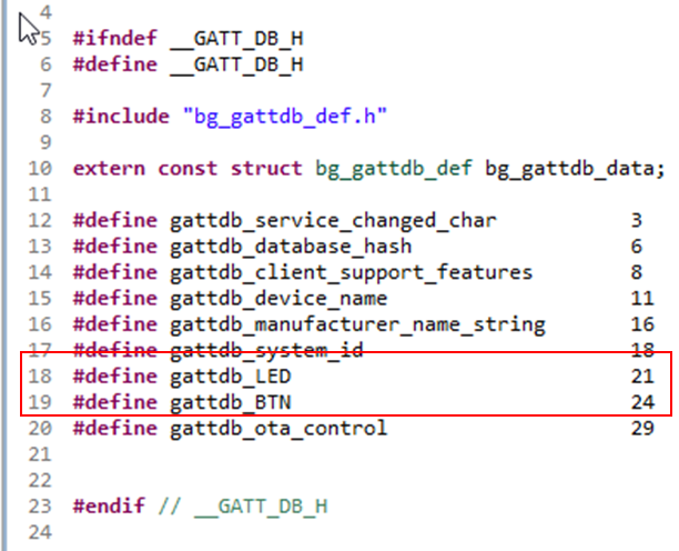
When the SLCP file is saved, the gatt_db files will be updated with the new characteristic as shown in the gatt_db.h file for the characteristic handles. The new gattdb_BTN handle will be used to create the notification in the Bluetooth stack.

Review the Simple button Firmware
Using the “Open Declaration” method, trace through the code until you get to the initialization of the button. Once the sl_simple_button_init_instances function is reached, stop there.
Take a look at the code in this file. The structure should look familiar as it is the same as the Simple LED structure with the button context and button type defined. These are the parameters that will be used to add the button functionality to the application.
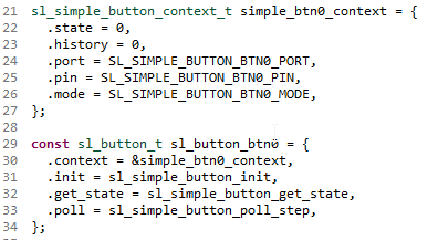

Take a look at the button context.
Within the structure there is the “state” and “history” elements. The state field is updated by the component firmware as the button is pressed and tells whether the button is high or low. The history field is not updated by the component firm-ware and can be used by the application.
Also note that the button is a component that can be instantiated multiple times and is supported by the simple_button_array[] declaration. This is useful for applications that have multiple buttons.
Take a moment to review the APIs associated with the button component.
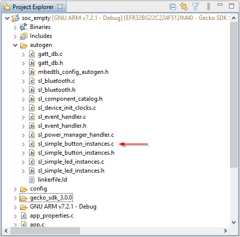
Find the button component firmware in the “Project Explorer” window and open the sl_button.c and sl_simple_button.c files.
(Hint: Up until now we have been looking at the autogenerated files that are a part of components. These files are platform component files that define how the component operates.)
The simple button initialization to configure the hardware is found in the sl_simple_button.c file. The initialization uses a combination of EMLIB and EMDRV APIs to set up the function.
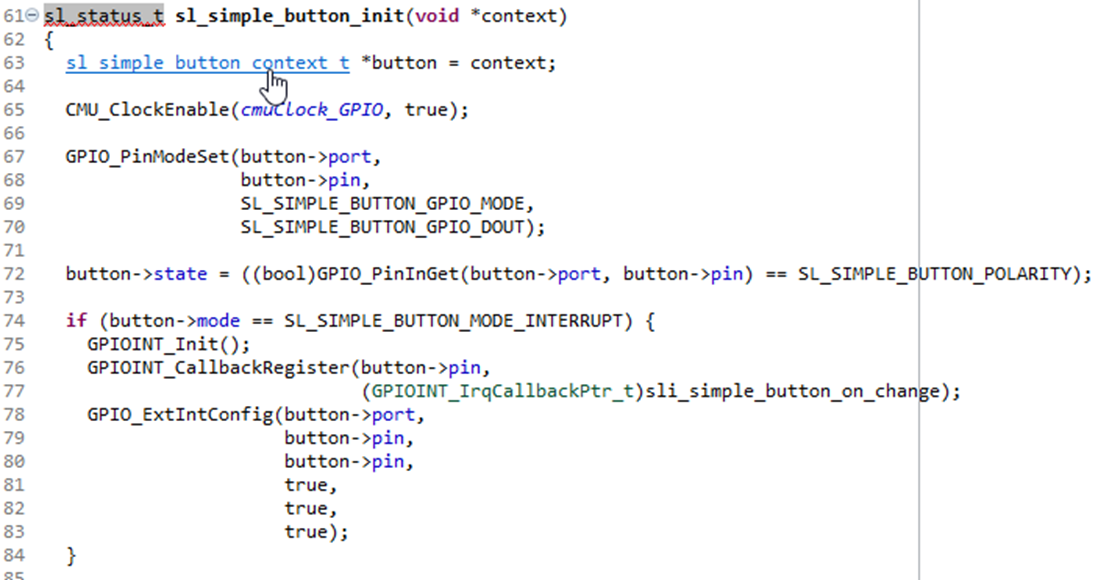

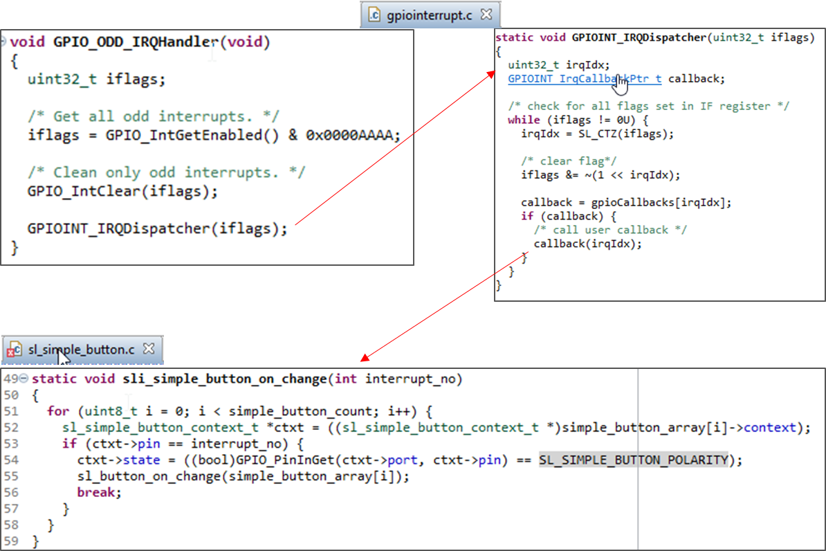
The GPIO EMDRV APIs enable a callback method to allow application developers to add code in interrupt context. What is the callback function name used by the simple button component?
When the button is pressed, the interrupt fires executing EMLIB and EMDRV APIs that contain the EVEN and ODD ISRs for the button. The IRQ Dispatcher calls the registered component callback. This is standard EMDRV firmware.
In the component callback function, the FW sets the current state of the button and calls a user callback function sl_button_on_change. This is a weakly defined function as part of the button component and is found in sl_simple_button.c. Having the function weakly defined allows the developer to override the placeholder function implementing the required actions for the button.
Note: An important concept to note here is that the button.state parameter represents the pin logic which may prove difficult to use for button action. The on change function should be used to add functionality based on the button press.

Adding the Component to the Bluetooth Framework#
At this point, the button component and the BTN characteristic have been added to the project. Now code needs to be added to the Bluetooth framework as well as the interrupt callback override function to process the button presses. When a server device wants to connect to a client, there are several steps in the process. The device has to advertise and connect if it is going to transfer data. The BT stack framework is structured where event IDs are used to create a loop to process the BT events. This section will add some code to events as well as create the notification event.
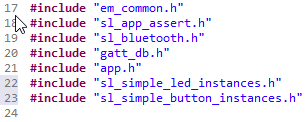
Open the app.c file. This file contains the event loop for the stack and is where the button firmware and notification firmware will be added. First, add the instance header file for the button.

The BTN characteristic was created as a notification to the host. The BT stack API for notification requires several items:
Handle for the characteristic
Pointer to the data buffer
Data length of the data buffer
The variables for the application are shown below. These values for the notification API parameters and the enable for the notifications to be sent from the firmware. These should be defined at the top of the file where the other variables are declared.
// The advertising set handle allocated from Bluetooth stack.
static uint8_t advertising_set_handle = 0xff;

// These variables need to be added and are used for the connection handle
// and the notification parameters to send Button data to the mobile app
uint8_t g_lab4Connection;
uint8_t notification_data[1] = {0};
uint16_t notification_len = 0;
uint8_t notifyEnabled = false;
By default, SoC_Empty starts up with advertising enabled. When a client requests a connection and the connection is made, the stack triggers a connection event using the sl_bt_evt_connection_opened_id. Using this event, the stack defined handle of the connection can be obtained. Get the connection handle by adding the following code to the connection opened event. This is the handle that will be needed when sending notifications.
    ///////////////////////////////////////////////////////////////////////////
    // This event indicates that a new connection was opened.                //
    ///////////////////////////////////////////////////////////////////////////
    case sl_bt_evt_connection_opened_id:

      // When sending notifications we need the connection handle.  Capture
      // it here
      g_lab4Connection = evt->data.evt_connection_opened.connection;
      break;
The BT stack adds the capability to process interrupts or other application level code via “external signaling”. By using the external signal API, the code execution remains within the BT framework avoiding potential issues such as timing which may manifest as dropped connections, and so on. Recall the weakly defined callback function for the component. The code below is the function to override that declaration. Remember that this function is called in interrupt context (on each edge of the button press) so the event signal API sl_bt_external_signal is used to notify the stack to generate an external event ID in the event loop. Add this code above the app_init function as shown below.
/*
 * Override function for button press that needs to be added.  This function is
 * called in interrupt context and uses the Bluetooth stack external signaling.
 */
void sl_button_on_change(const sl_button_t *handle)
{
  sl_simple_button_context_t *ctxt = ((sl_simple_button_context_t *)handle[0].context);
  if (ctxt->state) {
      ctxt->history += 1;
      sl_bt_external_signal(1);
  }
}

/**************************************************************************//**
 * Application Init.
 *****************************************************************************/
SL_WEAK void app_init(void)
{
  /////////////////////////////////////////////////////////////////////////////
  // Put your additional application init code here!                         //
  // This is called once during start-up.                                    //
  /////////////////////////////////////////////////////////////////////////////
}
The function increments the button context history each time it is pressed and activate an event. In this case, event ID 1. Add this function code outside the sl_bt_on_event function.
Now that we have generated an event signal, the event ID (sl_bt_evt_system_external_signal_id) needs to be added to the loop. The external signal case will be generated each time through the loop that the external signal API for the button is executed. The notification to send the number of active button presses (button history) can be sent during this time.
Add this new BT stack event code for the external signal after the code for the event to control the LED writes that has already been added in the app.c file. This was found after the comments identifying where to add additional events.
case sl_bt_evt_system_external_signal_id:
/* Process external signals */
if (notifyEnabled) {
if (evt->data.evt_system_external_signal.extsignals == 1) // 1 = BTN0
{
notification_data[0] = (uint8_t)simple_btn0_context.history;
simple_btn0_context.history = 0;
// send number of button presses
sc = sl_bt_gatt_server_send_characteristic_notification(
g_lab4Connection, gattdb_BTN, sizeof(notification_data),
notification_data, ¬ification_len);
}
}
break;This code writes the button history (number of active button presses) to the data payload for the notification and then sets the history back to 0 to indicate no more active button presses. Here the notification with the BT send_characteristic_notification API shown is also created. This API requires the handle that we obtained from the connection opened event (g_lab4Connection) and the handle for the BTN characteristic that was created using the GATT Configurator.
The client will not accept notifications until they are enabled. Once enabled, the client sends to the server a packet to signal that it is ready to receive notifications. From the stack perspective, this is signaled via an event called, “sl_bt_evt_gatt_server_characteristic_status_id.” The variable “notifyEnabled” will be used as the flag to enable the notification code, added in the previous step, to be sent to the client. Add the following code within the event loop to ena-ble/disable the notifyEnabled flag.
    case  sl_bt_evt_gatt_server_characteristic_status_id:
      if ((evt->data.evt_gatt_server_characteristic_status.characteristic == gattdb_BTN)
          && (evt->data.evt_gatt_server_characteristic_status.status_flags == 0x01)) {
   if (evt->data.evt_gatt_server_characteristic_status.client_config_flags == 0x00) {
         notifyEnabled = false;
   }
   else {
      notifyEnabled = true;
   }
}
break;
Build and download the code.
Was there an error? What was wrong?
The sl_simple_button_instances.h header file for the buttons includes the declaration of the higher-level structure but does not include a declaration for the button context by default. The history field of the context was used in this example to store the number of active button presses. Therefore, the declaration of the context will need to be added to our app.c file. Add the variable declaration to the top of the app.c file with the other variable declarations.
// These variables are used for the connection handle and the notification
// parameters to send Button data to the mobile app
uint8_t g_lab4Connection;
uint8_t notification_data[1] = {0};
uint16_t notification_len = 0;
uint8_t notifyEnabled = false;

extern sl_simple_button_context_t simple_btn0_context;
Note: There are several ways to accomplish this declaration. Another common way would be to declare it in the focus of the function such as:
sl_simple_button_context_t *ctxt = ((sl_simple_button_context_t *)sl_button_btn0.context);Build and download the code.
Using the EFR Connect app Browser, connect to the LED device, and select the “More Info” button on your custom service.
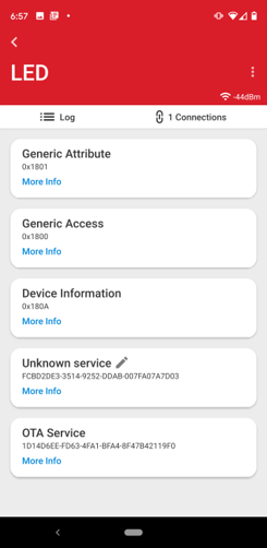

Notifications have to be enabled. To do this in EFR Connect select the Notify icon (


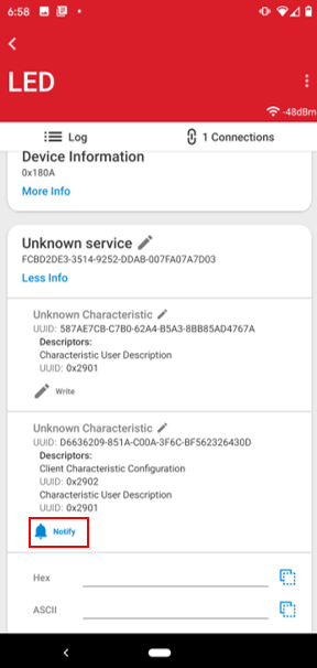

Navigate to the Log screen by selecting the Log tab (


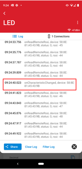

Click the Log tab again to go back to the previous screen.
Each time BTN0 is pressed the data value in the history field of the button component is updated. The FW then writes the stored button data to the data field for the notification characteristic. At that point the Bluetooth framework will send the button data to the mobile app. The line of code where the button history data is written to the notification data buffer is shown below.
notification_data[0] = (uint8_t)simple_btn0_context.history;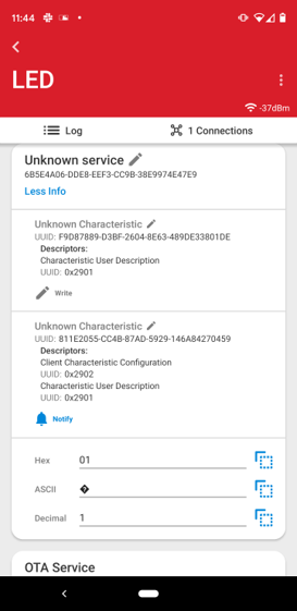

When running EFR Connect, you may have noticed that the data displayed is always 0x01. The app and firmware are running properly. This happens because there is no delay in processing and the history data is sent and then cleared after each button press.
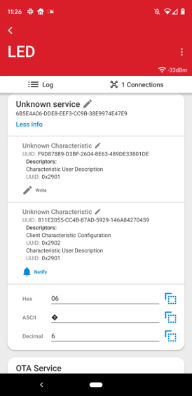
This example can be modified to show changing data values in the app by commenting out a line of code in the firmware. Comment out the line of code shown below that resets the history field to 0.
case sl_bt_evt_system_external_signal_id:
/* Process external signals */
if (notifyEnabled) {
if (evt->data.evt_system_external_signal.extsignals == 1) // 1 = BTN0
{
notification_data[0] = (uint8_t)simple_btn0_context.history;
//simple_btn0_context.history = 0;
// send number of button presses
sc = sl_bt_gatt_server_send_characteristic_notification(
g_lab4Connection, gattdb_BTN, sizeof(notification_data),
notification_data, ¬ification_len);
}
}
break;EFR Connect should now display the total number of times the button has been pressed.

Deeper Dive into Components and the Bluetooth Stack Summary#
Congratulations. Lab 4 demonstrated how to add an interrupt driven SSv5 component to a project and use the generated code to provide the functionality as well as adding a Bluetooth service to consume the component. The following topics were covered:
Using the Project Configurator to add and configure a component
Review the underlying generated component code framework
Viewing autogenerated files
Creating a custom characteristic
Adding a notification event to the Bluetooth framework
Adding an external signal event to the BT stack to support interrupt from peripherals
Used the context of the component to gain access to additional elements of the component
Use the EFR Connect mobile app to read data from a server device
