Learn How Peripheral Reflex System (PRS) Enables Complex I/O Logic#
Overview#
Maximizing energy efficiency in IoT battery applications is critical. Every micro-amp counts. Finding ways to reduce power can extend battery life considerably. Silicon Labs EFR devices offer multiple ways to help reduce power for a variety of applications. One of the biggest ways to improve energy efficiency is to limit the time the CPU spends executing code. With the CPU sleeping, the CPU tasks need to be offloaded to the hardware in the MCU. Instead of being in a paradigm where software running on the CPU does everything, software development should focus on setting up hardware to do the heavy lifting and only intervene when hardware needs assistance. In other words, hardware should be the main driver of the application doing the bulk of the work. The two main goals are to sleep as deeply as possible and wake up as seldom as possible.
The EFR32 devices feature a Peripheral Reflex System (PRS) with configurable logic allowing for combinational functions between channels. Multiple channels can be cascaded to produce more complex functions. This lab will demonstrate how to set up the PRS and implement complex logic functions such as a SR Latch using the Thunderboard (EFR32BG22). The training consists of two labs, each one highlighting a different complex logic function. Lab #1 will go through how to implement a XOR function using two inputs. Lab #2 will show how to implement a SR Latch.
PRS Topics covered
Producers and Consumers
Combinational Logic functions
Peripheral Reflex System#
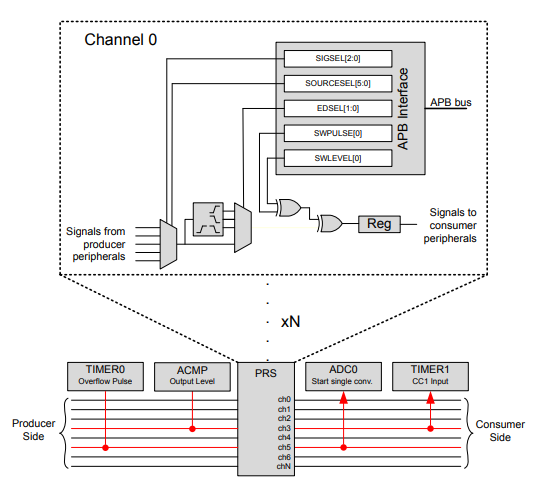

The Peripheral Reflex System (PRS) system is a signal routing network that lets the different peripheral modules communicate directly with each other without involving the CPU. Peripheral modules that send out reflex signals are called producers. Peripheral modules accepting reflex signals are called consumers. The PRS routes the reflex signals from producer to consumer peripherals.
This training will utilize two Asynchronous PRS Producers; the GPIO and RTCC peripherals. For the full list of Asynchronous PRS Producers, see the EFR32xG22 Wireless Gecko Reference Manual Section 13.3.3.1 Producer Details.
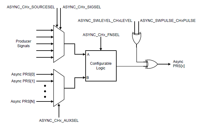

Within the PRS module, the configurable logic feature enables a PRS channel to perform logic operations on the signal coming from the selected producer. The configurable logic block for each channel has two inputs. The first input, Input-A, is the signal from the selected producer. The second signal, Input-B, is the output selected from another PRS channel. This allows for combinational functions where multiple channels can be cascaded to produce more complex functions.
Using the FNSEL field, a total of 16 two-input functions can be implemented.
FNSEL | Implemented Function |
|---|---|
0x0 | 0 |
0x1 | A NOR B |
0x2 | (NOT A) AND B |
0x3 | NOT A |
0x4 | A AND (NOT B) |
0x5 | NOT B |
0x6 | A XOR B |
0x7 | A NAND B |
0x8 | A AND B |
0x9 | A XNOR B |
0xa | B |
0xB | A OR (NOT B) |
0xC | A |
0xD | (NOT A) OR B) |
0xE | A OR B |
0xF | 1 |
For more information about the PRS, see the EFR32xG22 Wireless Gecko Reference Manual Section 13 PRS and AN0025: Peripheral Reflex System (PRS).
Creating the Base Project#
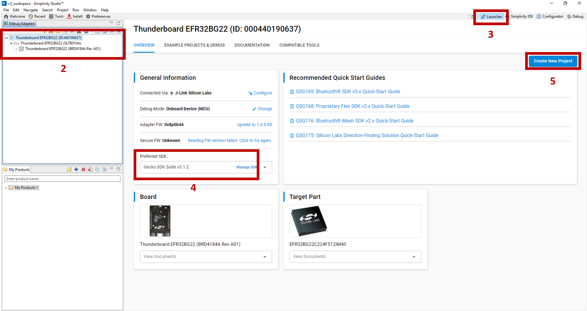
Open Simplicity Studio v5. If the Thunderboard BG22 has not been plugged in using the USB cable, do so now. The kit and debug information should be displayed in the Debug Adapters window.
In the
Debug Adapterswindow, click on the device.Information about the target hardware and software will appear. If this does not appear, click on the
Launcherbutton in the top right corner.Select the
Preferred SDKto the latest version. For this lab, the latest version of Gecko SDK (v3.1.2) is used.Click on
Create New Projectin the upper right hand corner. A "New Project Wizard" window should appear.

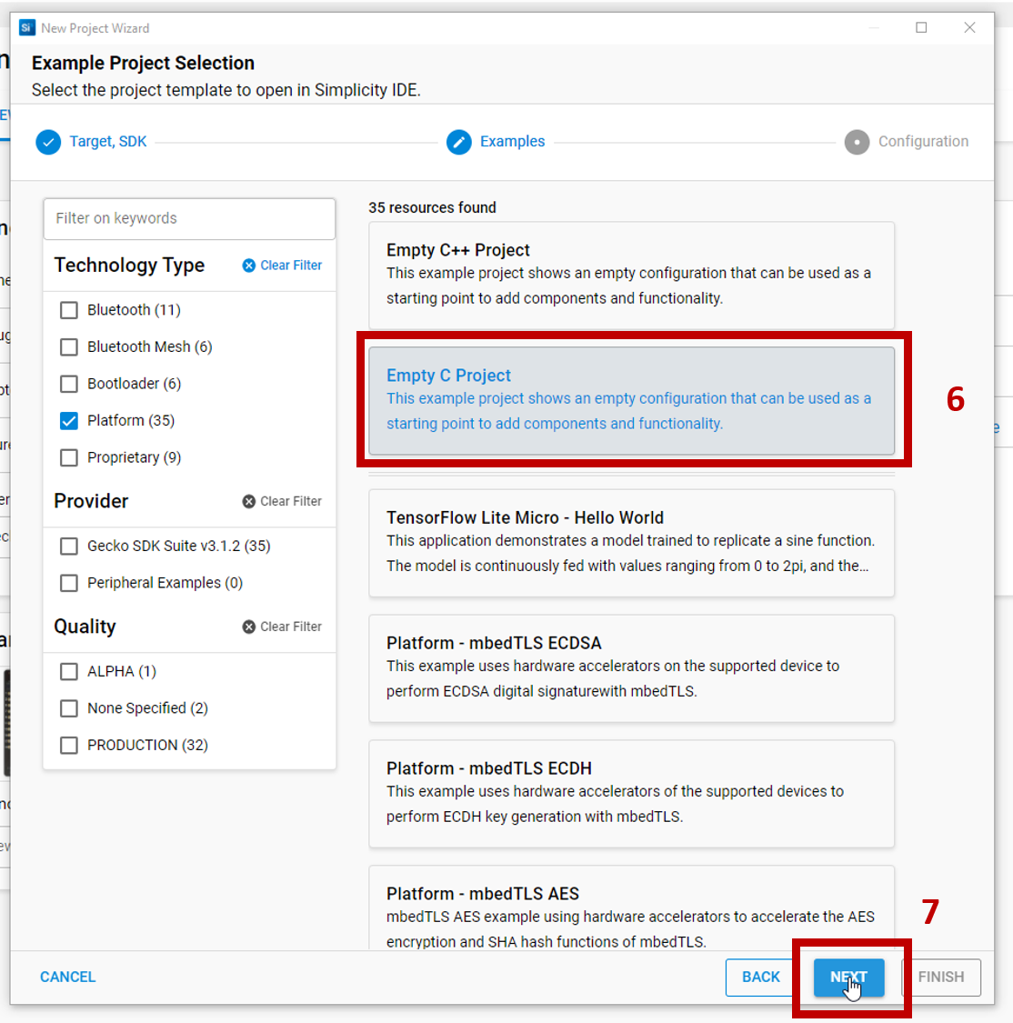
For this lab, the Empty C Project will be used as the starter project. Under the
Technology Typefilter window, select thePlatformfilter option. On the right under the resources list, scroll and select Empty C Project.Click
Nextto move on.

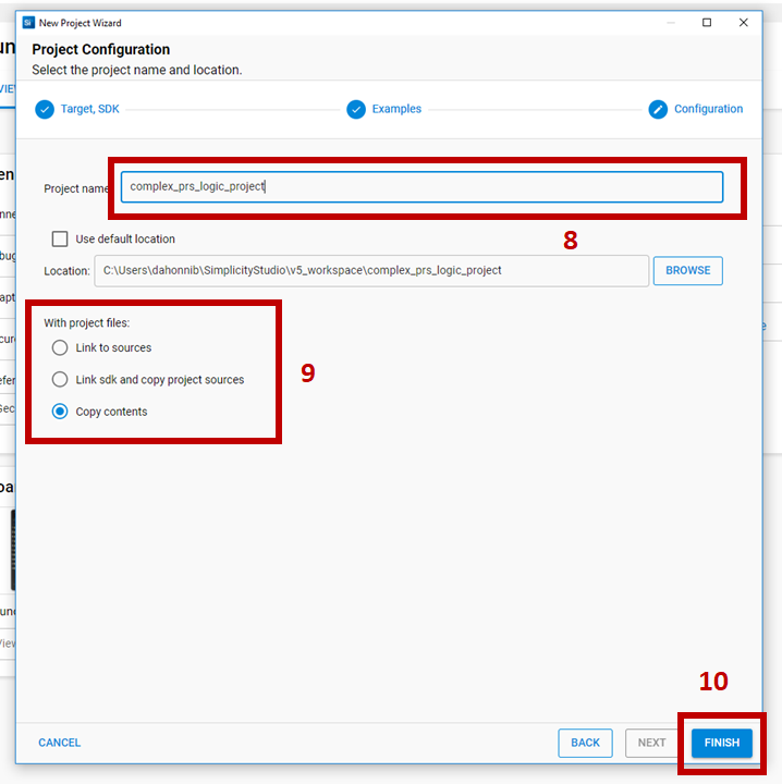
Rename the project. For this lab, name the project
complex_prs_logic_project.Select
Copy contentsto copy the project files into your project. This makes version control easier to manage and future updates to the Simplicity Studio libraries will not impact the copied files in this project.Link sdk and copy project sourcesis selected by default. This creates the new project in the Simplicity Studio workspace. It will link any library files from the SDK and copy any source files directly into the project folder.Click
Finishto generate the project.

Installing the EMLIB components#
Previously in SSv4, the desired EMLIB source files had to be manually copied to a project. Now in SSv5, the configurator can be used to install the source files. Open the
prs_complex_logic_project.sclpfile. The file will show information about the target hardware and software.Select the
Software Componentstab at the top.Scroll down to the "Platform" section. Notice how there are many components available that you can install for your application with ease.
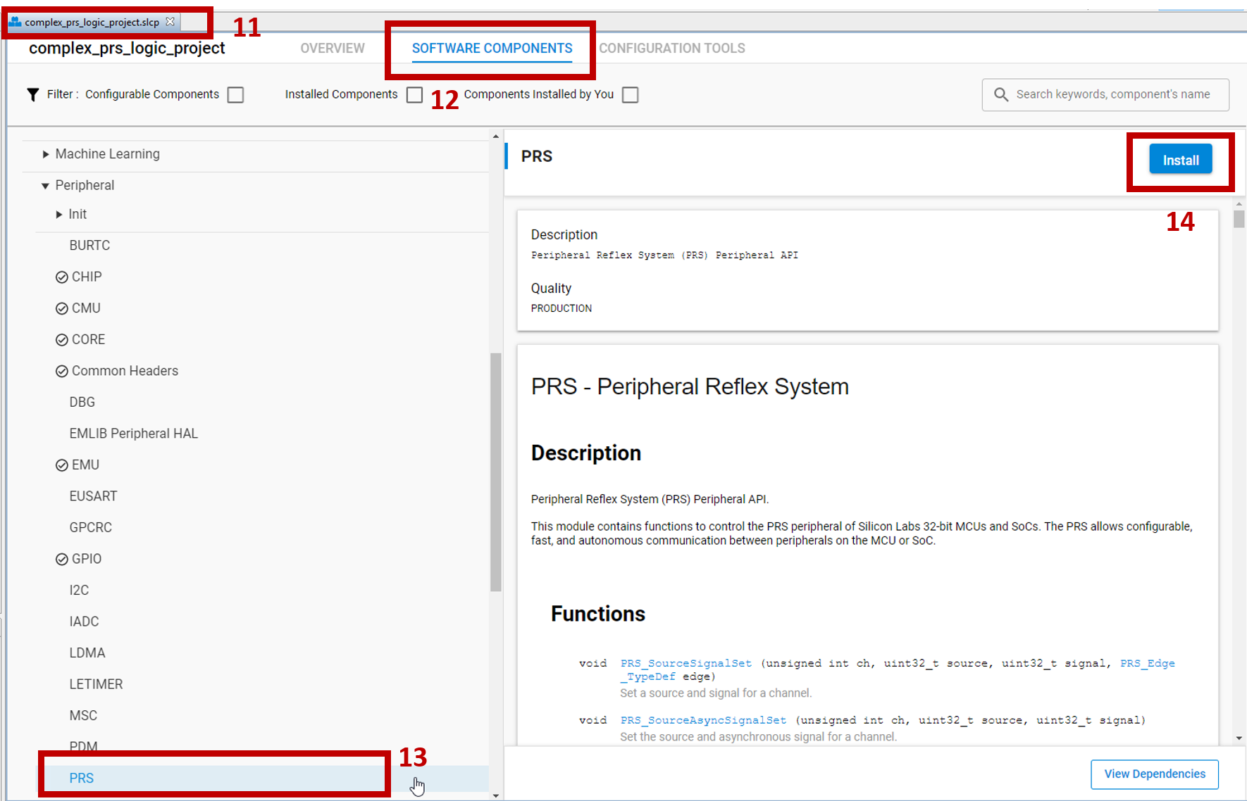

The list of EMLIB source files is available under "Peripherals". Install the following components using the
Installbutton as shown in the image.
PRSRTCC
Adding the Project Source Files#
This demonstration consists of two labs. There is an app.c file for each lab. Lab #1 uses app1.c and Lab #2 uses app2.c. Both Lab #1 and Lab #2 use app.h.
Source Files#
You'll need to copy the source files and paste them into your Simplicity Studio project folder. The path for you Simplicity Studio project folder should follow this:
./Users/JohnDoe/SimplicityStudio/v5_workspace/complex_prs_logic_projectOnce you've copied the source files, you'll need to delete the default app.c file that Simplicity Studio generates. Once you've deleted the default file and copied over the source files, your source folder should resemble this: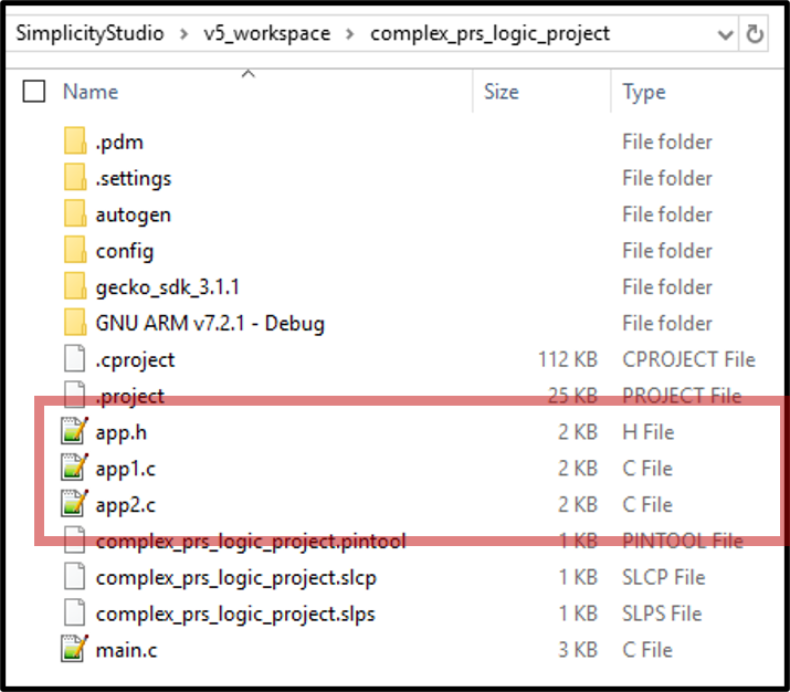

Excluding Source File from Build#
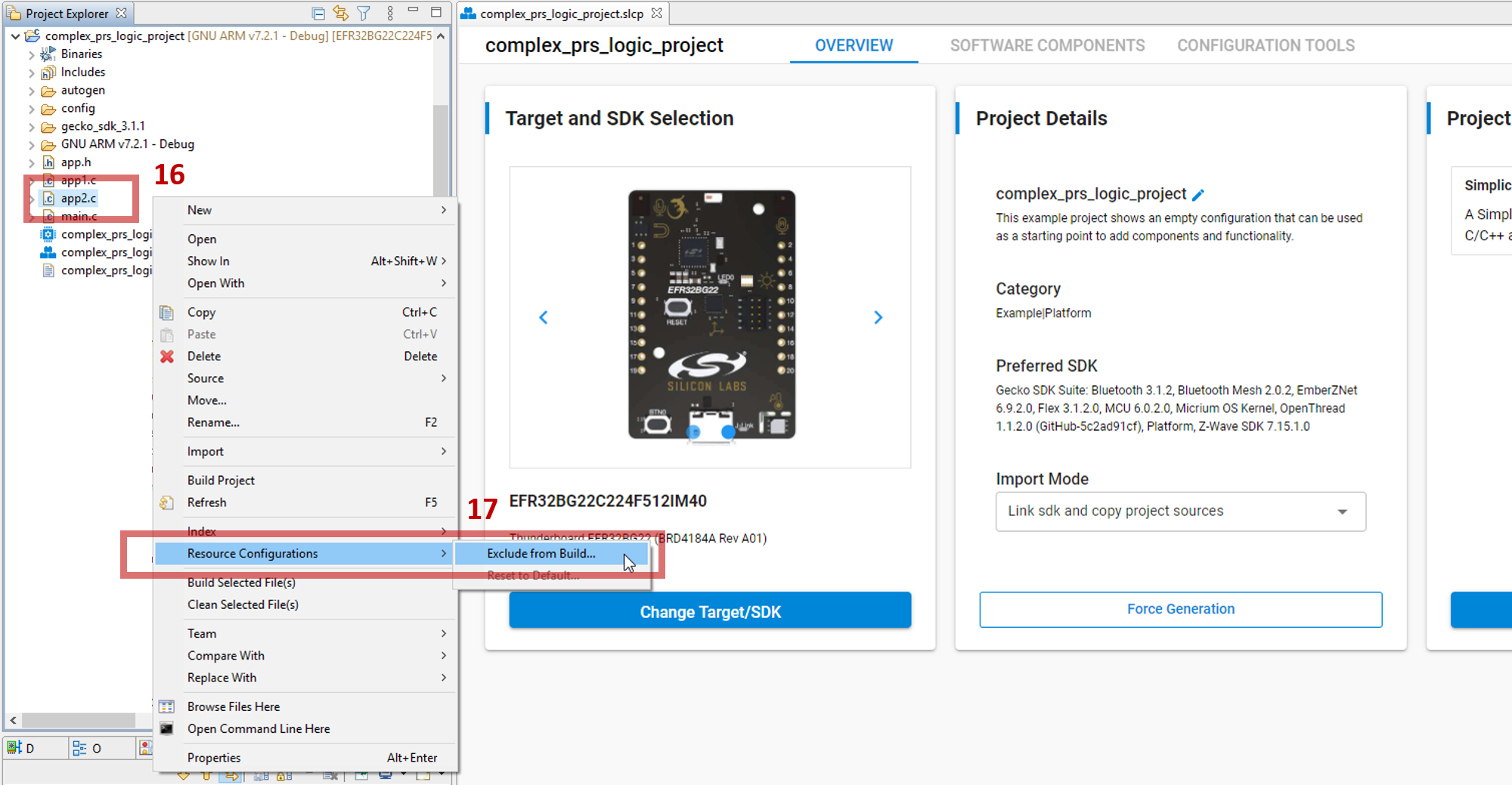

For each lab, an app[n].c file will need to be excluded from the build. For Lab #1, you'll exclude app2.c from the build. In the project explorer window, right click on the app2.c file.
In the right click menu, scroll down and select
Resource Configurations -> Exclude from Build.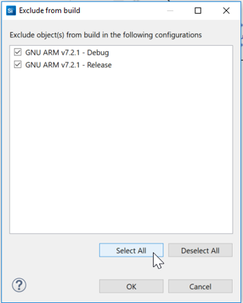

Select Alloption and continue. 18. Once excluded, the app2.c file will be grayed out in the Project Explorer window with a ' / ' over its icon.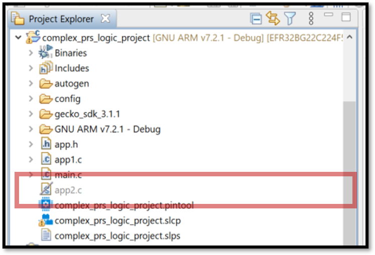

Build and Flash the Project#
Build the project by clicking on the hammer icon in the top left corner of the Simplicity Studio IDE. The project should build with no errors or warnings.
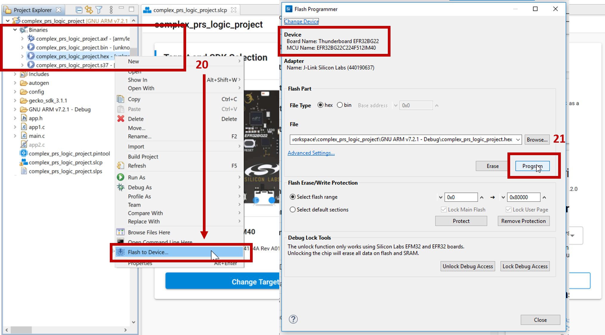
In the project explorer under the binaries folder, right-click on the hex file and select
Flash to Device...to make the Flash Programmer window appear. Note: if a Device Selection window appears, select the correct device.Click
Programto flash the device.

Lab 1#
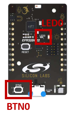

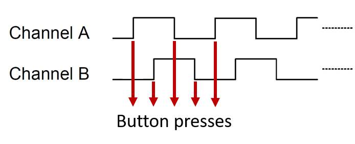
Lab #1 will demonstrate the XOR function of the PRS configurable logic with two inputs. The Thunderboard only has a single button for user input, push-button BTN0 located on the bottom left of the PCB's top side. The single push-button BTN0 will generate a quadrature encoder type signal as the two inputs for the XOR logic. The quadrature input will scroll through 4 different states as shown in the figure and table below. Each button press will scroll through the input sequence.

Sequence | A | B | (A XOR B) |
|---|---|---|---|
0 | 0 | 0 | 0 |
1 | 0 | 1 | 1 |
2 | 1 | 1 | 0 |
3 | 1 | 0 | 1 |
4 | 0 | 0 | 0 |
5 | 0 | 1 | 1 |
etc. | ... | ... | ... |
Each input, A and B, will be routed to their own PRS Channel. The two PRS Channels will then be configured as inputs to the PRS Configurable logic with the XOR function selected. The output of the XOR function will be routed to the Thunderboard's LED LED0 located in the middle of the PCB. Every time you press the push-button BTN0, the LED0 will toggle due to the XOR function.


Application#
Let's look at app1.c to see how the project is configured.
The GPIO peripheral is initialized by the init_gpio() static function in line 72. The two input waveform GPIOs are configured in line 89 and 90. The pin configuration is an input with a pull-down resistor to start. The input pull-up or pull-down resistor will be used to toggle the input waveforms high or low for each button press.
  /* Configure inputs */
  GPIO_PinModeSet(INPUT_PORT, INPUT_A_PIN, gpioModeInputPullFilter, 0);
  GPIO_PinModeSet(INPUT_PORT, INPUT_B_PIN, gpioModeInputPullFilter, 0);
Push-button BTN0 is configured as a GPIO input with an interrupt in line 78.
  /* Configure Button PB0 as input and enable interrupt */
  GPIO_PinModeSet(TB_BUTTON_PORT, TB_BUTTON_PIN, gpioModeInputPull, 1);
  GPIO_ExtIntConfig(TB_BUTTON_PORT,
                    TB_BUTTON_PIN,
                    TB_BUTTON_PIN,
                    false,
                    true,
                    true);
  NVIC_ClearPendingIRQ(GPIO_ODD_IRQn);
  NVIC_EnableIRQ(GPIO_ODD_IRQn);
The push button's GPIO IRQ updates a static flag updateOutput every time the push-button is pressed.
void GPIO_ODD_IRQHandler(void)
{
  /* Get and clear all pending GPIO interrupts */
  uint32_t interruptMask = GPIO_IntGet();
  GPIO_IntClear(interruptMask);

  /* Check if button 1 was pressed */
  if (interruptMask & (1 << TB_BUTTON_PIN))
  {
    updateOutput = true;
  }
}
The updateOutput flag is handled by the app_process_action() function in line 128. The updateOutput flag indicates that the static quadrant variable needs to be changed to the next quadrant assignment. Then the GPIO configuration is changed accordingly so that the GPIO input pull-up or pull-down resistor is set.
  if(updateOutput)
  {
    updateOutput = false;
    /* If button press has occurred, update the quadrant status */
    if(quadrant == 3) {
        quadrant = 0;
    } else {
        quadrant++;
    }
    /* After updating quadrant count, set output accordingly */
    if (quadrant == 0) {
        GPIO_PinModeSet(INPUT_PORT, INPUT_A_PIN, gpioModeInputPullFilter, 0);
        GPIO_PinModeSet(INPUT_PORT, INPUT_B_PIN, gpioModeInputPullFilter, 0);
    } else if (quadrant == 1) {
        GPIO_PinModeSet(INPUT_PORT, INPUT_A_PIN, gpioModeInputPullFilter, 0);
        GPIO_PinModeSet(INPUT_PORT, INPUT_B_PIN, gpioModeInputPullFilter, 1);
        ...
The PRS Peripheral is initialized in line 53. Each input A and B is set as an Asynchronous Source Signal for their own PRS Channels.
  // Use inputs as PRS source
  PRS_SourceAsyncSignalSet(PRS_CH_A, PRS_ASYNC_CH_CTRL_SOURCESEL_GPIO, INPUT_A_PIN);
  PRS_SourceAsyncSignalSet(PRS_CH_B, PRS_ASYNC_CH_CTRL_SOURCESEL_GPIO, INPUT_B_PIN);
Next the configurable logic function is defined with the two inputs. First, the PRS_Combine() API sets PRS_CH_B as a buffer where PRS_CH_B equals PRS_CH_B(in). Then PRS_CH_B is routed to the XOR logic input with PRS_CH_A(in). The resulting XOR output is PRS_CH_A.
  // Configure PRS logic for XOR Ch_A(out) = Ch_A(in) XOR Ch_B(out)
  PRS_Combine(PRS_CH_A, PRS_CH_B, prsLogic_A_XOR_B);
Lastly, PRS_CH_A, the XOR output, is routed to the LED GPIO through the PRS.
  // Route PRS CH_A(out) to LED
  PRS_PinOutput(PRS_CH_A, prsTypeAsync, TB_LED_PORT, TB_LED_PIN);
Please note the selection of the PRS_CH_A channel which is defined in line 44. PRS_CH_A is assigned to PRS Channel 2.
#define PRS_CH_A 2The Thunderboard's LED is located at gpioPortB, Pin 2 on the EFR32BG22. Therefore, PRS_CH_A must be a PRS Channel between 0 and 5. EFR32xG22 Wireless Gecko Reference Manual Section 25.3.12.3 GPIO Pin Functions covers the allowed PRS Channels per GPIO Ports. As shown in the table, GPIO Ports A and B can only use Channels 0 to 5. GPIO Ports C and D can use Channels 6 to 11.
Lab 2#
For Lab #2, exclude the app1.c source file just as before. See Excluding Source Files from Build section above. After app1.c is excluded from the build, include the app2.c that was excluded originally. Similarly, right-click on the app2.c file. Select Resource Configuration->Exclude from Build. Then choose De-select All and press OK. Project Explorer should show app1.c file named grayed out and app2.c normal.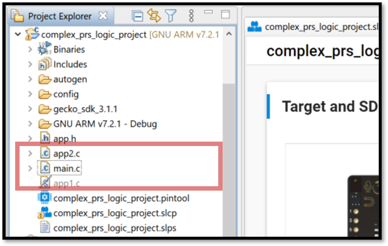

Lab #2 will demonstrate a SR Latch using the PRS configurable logic. The SR latch will be implemented using two NAND gates since it utilizes two active low inputs: Set (S bar) and Reset (R bar). The figure below shows the SR Latch configuration with its truth table.


S | R | Action |
|---|---|---|
1 | 1 | No change |
1 | 0 | Q = 0 |
0 | 1 | Q = 1 |
0 | 0 | Not allowed; Q = 1 |
The Thunderboard's single push-button BTN0 will be used to generate the Set signal which brings the I/O low when pressed. Since the Thunderboard has only one single button for user input, the RTCC Peripheral will be used to periodically toggle the Reset signal. Only the SR Latch output Q will be used for the lab and will be routed to the Thunderboard's LED.
While the Set signal (button) maintains its high state by default, the Reset signal (RTCC) will toggle periodically resulting in a constant low output that turns the LED off. The RTCC is configured to toggle with a 3 second period. If the button is pressed (Set=low) while the Reset signal is high, the Q output will toggle turning the LED on. Once the Reset signal is toggled, the Q output will go back low and the LED will turn off.
If the push-button is pressed while the Reset signal is low, the output will stay high as long as the push-button is held low. This is deemed a "Not Allowed" state since it breaks the desired output behavior.
Application#
The source file app2.c shows how all the peripherals are configured.
The RTCC is initialized in line 53. The RTCC is configured to run off of the ULFRCO with a nominal frequency of 1kHz. The RTCC is set to trigger on a CC1 Compare Match. Upon a compare match, the RTCC will toggle the PRS input. The RTCC period is determined in line 77. The desired RTCC period is 3 seconds which runs off of the 1kHz ULFRCO oscillator.
  //Setting the CC1 compare value of the RTCC
  RTCC_ChannelCCVSet(1, (1000 * 3000) / 1000 - 1);
The GPIOs are initialized in line 93. The Thunderboard LED is set as an output push-pull. The Thunderboard push-button is set as an input. Notice that the push-button interrupt signal is configured but it is left disabled with both rising and falling edge settings nulled.
  /* Configure Button PB0 as input and configure interrupt */
  GPIO_PinModeSet(TB_BUTTON_PORT, TB_BUTTON_PIN, gpioModeInputPull, 1);
  GPIO_ExtIntConfig(TB_BUTTON_PORT, TB_BUTTON_PIN, TB_BUTTON_PIN, 0, 0, false);
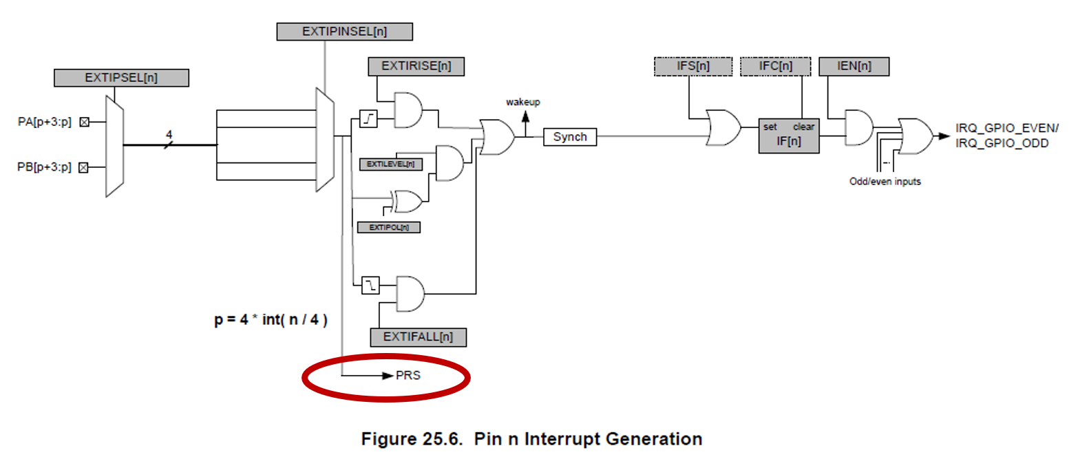
The PRS output is not affected by the interrupt edge detection logic or gated by the IEN bits. The pin from which the output should be taken is selected in the same fashion as the edge interrupts. Figure 25.6 in EFR32xG22 Wireless Gecko Reference Manual Section 25.3.10 GPIO Interrupt Generation illustrates where the PRS output signal is generated.

The PRS Peripheral is initialized in line 110. The PRS_Combine() API can't be used for this scenario. As shown in Lab #1, the PRS_Combine() API sets the input B PRS channel as a buffer. In this lab, each NAND gate will have feedback from the other NAND gate's output. Therefore, the PRS Asynchronous Channel Control registers need to be set individually. The register and bit fields are show in EFR32xG22 Wireless Gecko Reference Manual Section 13.5.6.
![PRS ASYNC CH[n] CTRL Register](/bluetooth-lab-manuals/0.0.32/images/3-3-prs-async-ctrl-register.png)
![PRS ASYNC CH[n] CTRL Register](/bluetooth-lab-manuals/0.0.32/images/3-3-prs-async-ctrl-register.png)
4 bit fields are required:
Name | Description |
|---|---|
SIGSEL | Signal input from the source peripheral. |
SOURCESEL | The selected peripheral |
FNSEL | The logic function |
AUXSEL | The ASYNC PRS channel corresponding to Input B for the logic function |
First, the Reset signal is configured. We're using the RTCC with a 3 second period to generate a 1 msec clock pulse that is active high. The NAND gate SR Latch requires an active low input for both Set and Reset. Therefore, invert the Reset signal using the PRS logic function.
  /* Configure PRS Channel to Invert the Reset signal */
  PRS->ASYNC_CH[PRS_CH_RESET].CTRL = (0 << 24) |
                                     (prsLogic_NOT_A << 16) |
                                     (PRS_ASYNC_CH_CTRL_SOURCESEL_RTCC) |
                                     (PRS_ASYNC_CH_CTRL_SIGSEL_RTCCCCV1);
Next, the inverted Reset signal is configured. The output of the PRS Channel used to invert the Reset signal is used as the input signal source. PRS_CH_RESET was defined as PRS Channel 2. Therefore SOURCSEL is set to PRS_ASYNC_CH_CTRL_SOURCESEL_PRSL which means that the PRS Channel used is one of the PRS CHannels 0 to 7. SIGSEL is set to PRS_ASYNC_CH_CTRL_SIGSEL_PRSLASYNCH2 which indicates PRS Channel 2 is selected.
The PRS logic function is set for a NAND operation. The secondary input for the PRS Logic function, AUXSEL, is set to PRS_CH_SET. PRS_CH_SET is the output of the other NAND Gate logic function.
  /* Configure PRS Channel for Inverted Reset signal */
  PRS->ASYNC_CH[PRS_CH_RESET_BAR].CTRL = (PRS_CH_SET << 24) |
                                     (prsLogic_A_NAND_B << 16) |
                                     (PRS_ASYNC_CH_CTRL_SOURCESEL_PRSL) |
                                     (PRS_ASYNC_CH_CTRL_SIGSEL_PRSLASYNCH2);
Next, in line 128, the Set signal is configured. The Thunderboard push-button is configured as the PRS signal source, therefore the SOURCESEL is set for Asynchronous GPIO where TB_BUTTON_PIN indicates the pin number used. We'll be using a NAND gate where the output of the inverted Reset signal is used as the other input.
  /* Configure PRS Channel for Set signal */
  PRS->ASYNC_CH[PRS_CH_SET].CTRL = (PRS_CH_RESET << 24) |
                                   (prsLogic_A_NAND_B << 16) |
                                   (PRS_ASYNC_CH_CTRL_SOURCESEL_GPIO) |
                                   (TB_BUTTON_PIN);
Lastly, the output of the Set PRS logic is routed to the EFR's GPIO peripheral so it can drive the Thunderboard's LED.
  /* Route PRS output of Set signal to Thunderboard LED */
  PRS_PinOutput(PRS_CH_SET, prsTypeAsync, TB_LED_PORT, TB_LED_PIN);
Use Case#
Sensors are the eyes and ears of IOT applications. Let’s consider a small temperature sensor node with a NTC thermistor where the EFR can enable the ADC peripheral while in a deep sleep mode. The typical current needed to drive a thermistor is about 33uA assuming a 3.3V supply. If you were to drive the thermistor using the EFR’s I/O, you could reduce supply current by disabling the thermistor when it’s not in use.

Duty-cycling the thermistor properly will maximize energy efficiency. EFR devices feature a Peripheral Reflex System (PRS), which allows each peripheral block to trigger another. In this example, the RTC would be used to trigger the ADC and enable the thermistor I/O via PRS to measure the thermistor voltage for a short period while sleeping for long periods in between. Ideally, the thermistor would only be active and consuming power while the ADC was sampling.
In low-power deep sleep applications, the EFR’s RTC would typically run off a 32kHz clock. If the thermistor I/O was enabled directly from the RTC event, the thermistor would be active for ~31 usec while the EFR’s minimum ADC sampling time is ~7 usec. This would result in the thermistor being enabled for ~24 usec longer than necessary.


Ideally, a signal should go high on the RTC trigger and low when the ADC conversion is complete. That signal can then automatically enable the thermistor system optimizing the thermistor’s duty-cycling. The EFR’s PRS logic functions allow this. The circuit shown below illustrates how to implement it using the PRS logic functions.
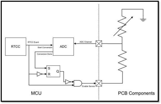

Initially, the latch output Q is low because the RTC event output and the ADC conversion done output are low. Whenever the RTCC event now goes high, the external sensor is enabled and the ADC starts taking a sample. Once the ADC is done, the conversion done signal goes high, setting the latch output Q high, which forces the external sensor off. When the RTC event signal goes low again, the latch is reset, making the system ready for the next event.
Using the ADC autonomously running in EM2, with PRS for optimal excitation of the thermistor, as shown here, maximizes energy efficiency prolonging battery life.
To learn more about maximizing energy efficiency with Silicon Labs EFR products, read Manage the IoT on an Energy Budget.
