Quickly Add an Accelerometer with SPI#
Overview#
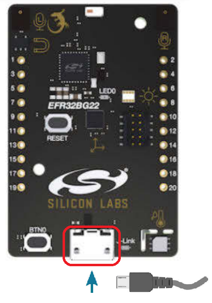
IOT (Internet of Things) solutions often use accelerometer sensors, such as an IMU (Inertial Measurement Unit). The EFR32BG22 Thunderboard (kit SLTB010A) has an on board 6-axis ICM-20648 sensor from vendor TDK InvenSense.
This lab shows how to quickly and efficiently add the accelerometer sensor.
Topic Covered
Accelerometer (Inertial Measurement Unit) sensor
Software component
EFR Connect app
Getting Started#
Ensure that you have the correct hardware and software prepared to successfully complete the lab.
Hardware Requirements#
Silicon Labs EFR32BG22 Thunderboard kit: SLTB010A The kit includes the following:
6-axis IMU (Inertial Measurement Unit): TDK InvenSense ICM-20648 with SPI interface
A mobile device for installing EFR Connect Mobile App: Android or Apple iPhone/iPad
Software Requirements#
Gecko SDK Suite v3.1 (GSDK) or above with the Bluetooth Stack (v3.1.1) installed
EFR Connect Mobile App
Install Tools#
Download and install Simplicity Studio v5 if not already installed. Ensure that you have GSDK 3.1.x and Bluetooth Stack installed.
Connect your Hardware#
Attach the EFR32BG22 Thunderboard kit to the PC with Simplicity Studio installed by using a USB cable (not a charging cable). Connecting between the PC host USB port and the J-Link USB port (USB micro) on the kit.
Hardware and Software Introduction#
Connection between IMU Sensor and EFR32BG22#
See the EFR32BG22 Thunderboard schematic for detailed hardware information (schematic for EFR32BG22 Thunderboard in PDF format).
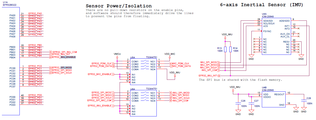
The following are the EFR32BG22 pins used to connect ICM-20648:
SPI interface:
SPI_MOSI (PC00)
SPI_MISO (PC01)
SPI_SCLK (PC02)
SPI_CS (PB02)
IMU_INT (PB03)
IMU_ENABLE (PB04)
EFR32BG22 USART(SPI) Peripheral#
EFR32BG22 has 2 USART peripheral instances. The USART peripheral is a flexible I/O module, which supports the following modes:
Full duplex asynchronous UART communication with hardware flow control as well as RS-485
SPI
Others
See the EFR32xG22 Wireless Gecko Reference Manual Section 21 on how to use this peripheral. The ICM-20648 sensor on EFR32BG22 Thunderboard uses the SPI interface. The sensor also supports I2C Fast Mode.
Accelerometer Sensor ICM-20648#
This sensor provides the following:
Orientation, 3-axis gyroscope.
Acceleration, 3-axis accelerometer.
Note: The sensor supports features such as calibration, auxiliary I2C interface, and others. In this lab, features like calibration were not included.
Software Architecture#
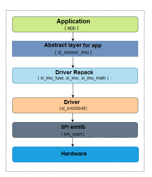
Below is an overview of the software architecture:
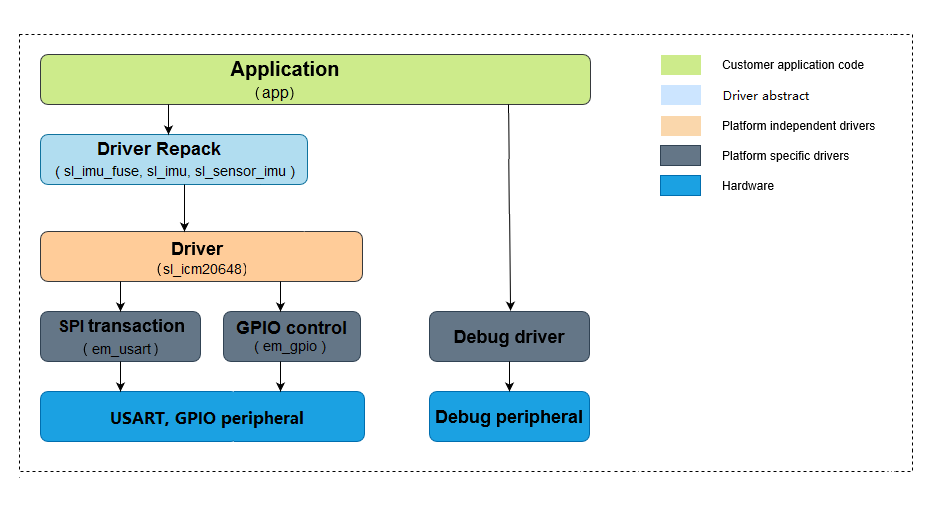
The figure shows the following:
Customer application code, which is custom developed by users according to their application requirements
Driver abstract, which is code developed by Silicon Labs. It contains routines provided by vendors that are “repacked” to simplify calling from the application.
Platform-independent drivers, which is code developed by both IMU vendors and Silicon Labs to connect the IMU device with multiple Silicon Labs devices. It also supports setup for registers specific to the IMU device.
Platform-specific drivers, which is code developed by Silicon Labs that executes drivers using appropriate low-level peripherals that may differ depending on a device/board.
Hardware, which are Silicon Labs peripherals on EFR32/EFM32 devices.
Lab#
Creating the Project#
If the EFR32BG22 Thunderboard isn't plugged into the PC using the USB cable, do so now.
In the
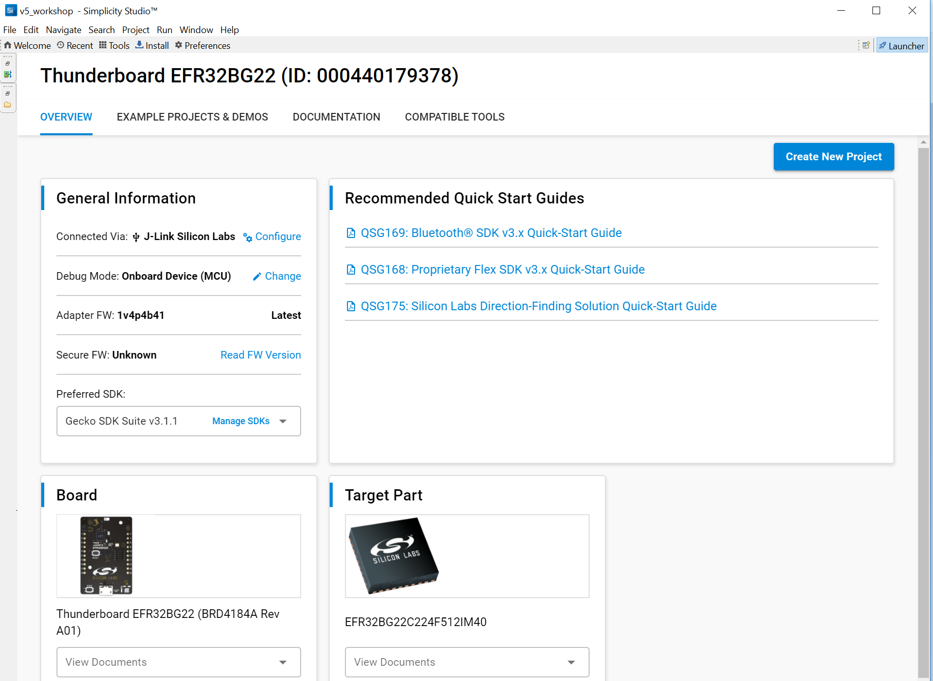
Launcher->Debug Adapterswindow, click on theThunderboard EFR32BG22 (ID:xxxxxxxxx). Thekit(end with SLTB010A),board(end with BRDxxxxx Rev Axx) anddevice(EFR32BG22CxxxFxxxxxxx) debug information should be displayed in theLauncher->Debug Adapterswindow.
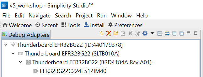
Information about the target hardware and software will appear in
Launcher->Overviewtab (together with theAdapter FWandSecure FWversion). If this does not appear, click on theLauncherbutton in the top right corner.
Note: If the Secure FW shows as Unknown, click on Read FW Version on the right side of it to get the version.
You may also upgrade the Adapter FW to the latest version.
Select the
Preferred SDKto the latest version. For this lab, the latest version ofGecko SDK Suite v3.1.1is used.Click on
Create New Projectin the upper right-hand corner. ANew Project Wizardwindow should appear.
Note: If you already have projects in the workspace, you may not see the Create New Project button. You can try other options to create a new project, e.g., File->New->Silicon Labs New Project Wizard... or 'Examples Projects & Demos' tab.
For this lab, the
Bluetooth - SoC Emptyproject is used as the starter project. Scroll and selectBluetooth - SoC Empty.
Note: To filter the projects, Select/Checked the Bluetooth for the Technology Type and input empty for Filter on keywords.
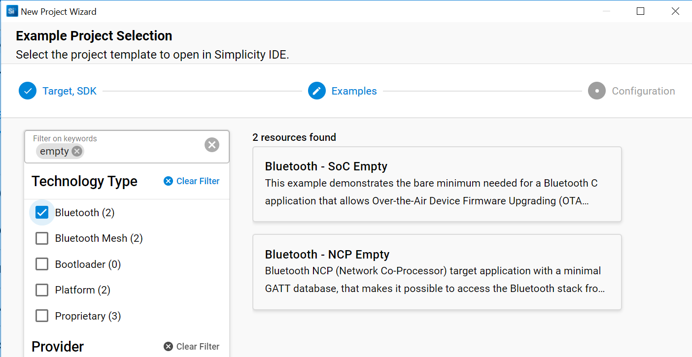
Click
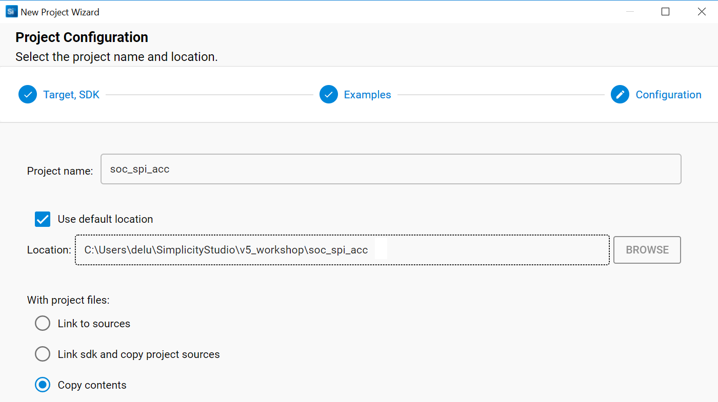
Nextto move on.Rename the project under
Project name. For this lab, name the projectsoc_spi_acc.Select (check)
Copy contentsunderWith project filesto copy the project files into your project. This makes version control easier to manage and future updates to the Simplicity Studio libraries will not impact the copied files in this project.Check
Use default location(workspace).Click
Finishto generate the project.
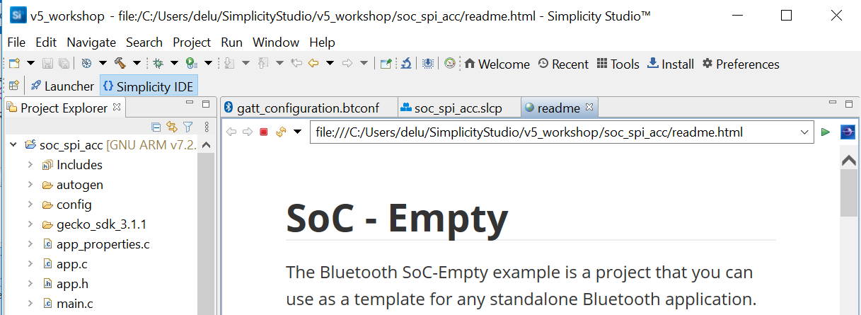
The
IDE perspectivelaunched automatically.You can now see
gatt_configuration.btconf,soc_spi_acc.slcpandreadme.
Summary of Previous Steps#
Congratulations! The SoC Empty is successfully created. Additionally, the Bluetooth - SoC Empty project will pre-install some software components.
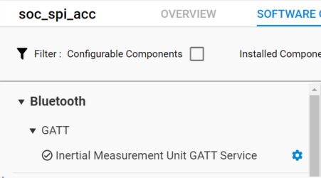
To see what was installed, check the Installed Components under Software Components.
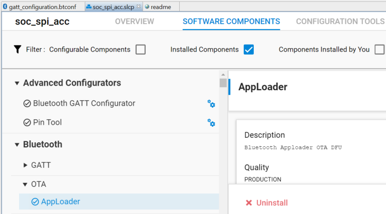
You will see that the following components were installed.
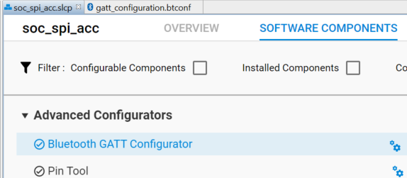
Advanced Configurators->Bluetooth GATT Configurator
Bluetooth->OTA->AppLoader
Platform->Services->Sleep Timer, and so on
If you don't see these components, make sure that you followed the procedure described above.
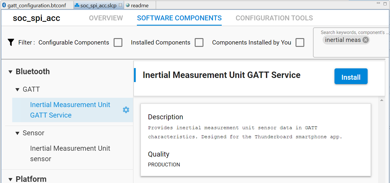
Installing the IMU Sensor Software Components#
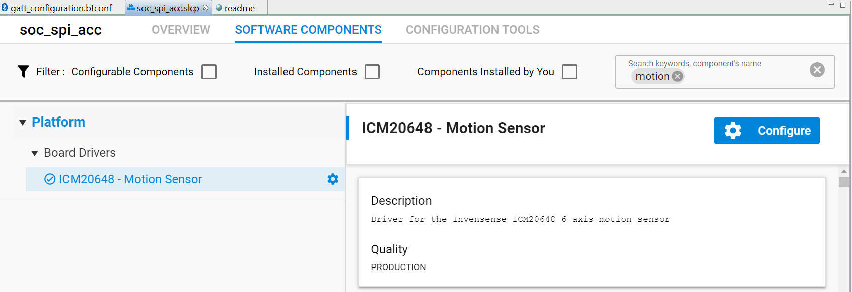
Select the
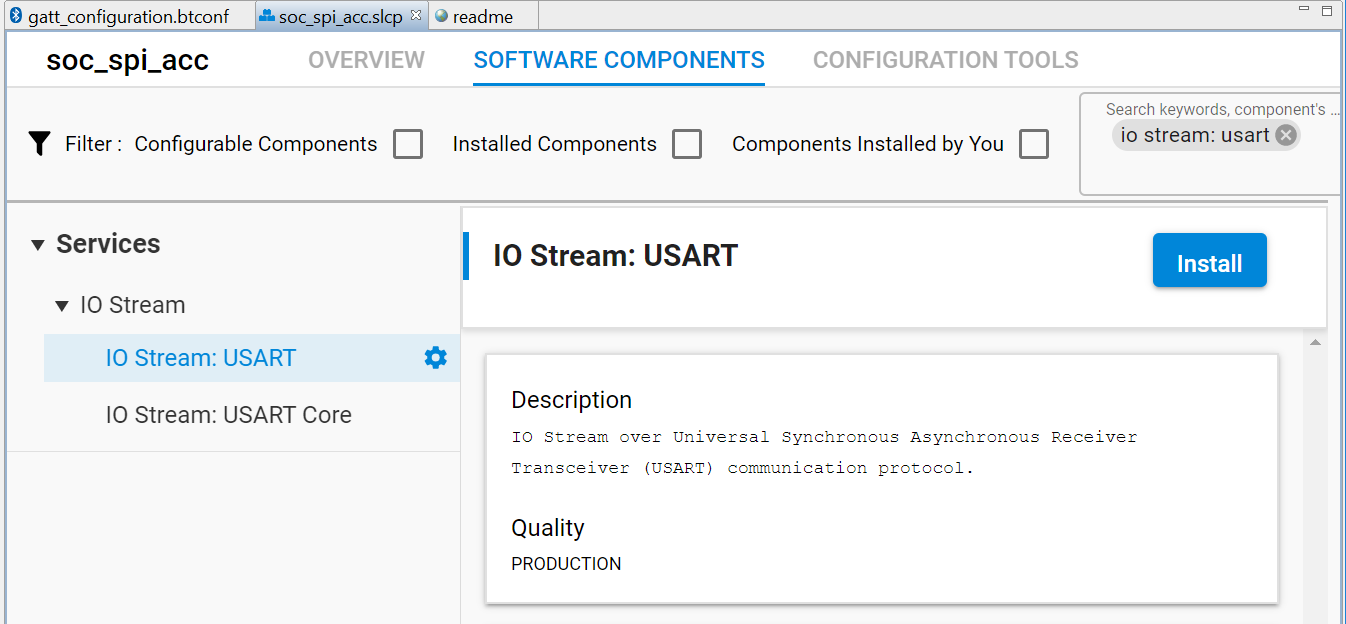
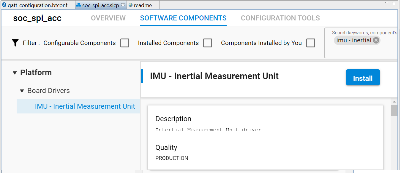
Software Componentstab on the top.Scroll downto the different sections (such asPlatform). Note all of the components that you can easily install for your application.Install the following components using the
Installbutton, as shown in the image. The process is repeated for all components that need to be added.
Services->IO Stream->IO Stream: USART(dependency)Platform->Board Drivers->IMU - Inertial Measurement UnitBluetooth->Sensor->Inertial Measurement Unit sensorBluetooth->GATT->Inertial Measurement Unit GATT Service
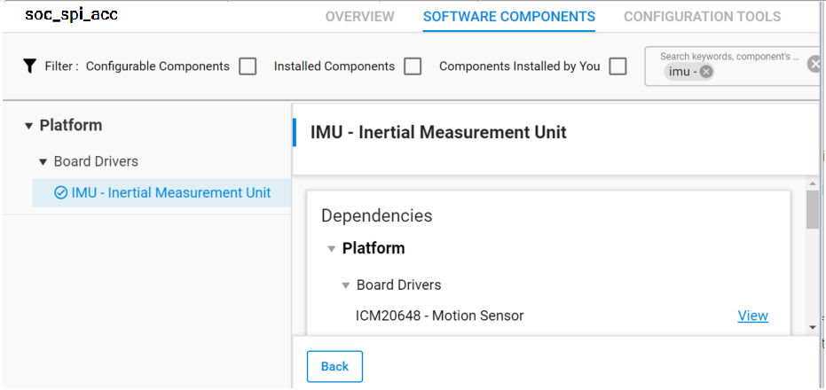
For example, take a look at the information shown on the right side of the view for the IMU - Inertial Measurement Unit component. Usually information such as Description, Quality level, and Dependencies of the component is provided. The view also provides a good overview of all functions that are defined/added for this component.
If you click the View Dependencies button, you can see that one of dependency components is Platform->Board Drivers->ICM20648 - Motion Sensor.
Installing the component IMU - Inertial Measurement Unit will also automatically install Platform->Board Drivers->ICM20648 - Motion Sensor.
Note: You can input a keyword on the upper right side of Search keywords, component's name box to filter the component. For example, the keyword inertial will cause only the last three components above to be visible.
Note: Although IMU - Inertial Measurement Unit is classified as a Board Driver, you can still install it even when using a custom board. However, you must configure the dependency component Platform->Board Drivers->ICM20648 - Motion Sensor to match pinouts of your custom board. Otherwise, the build will report errors, as will be shown in the code explanation section.
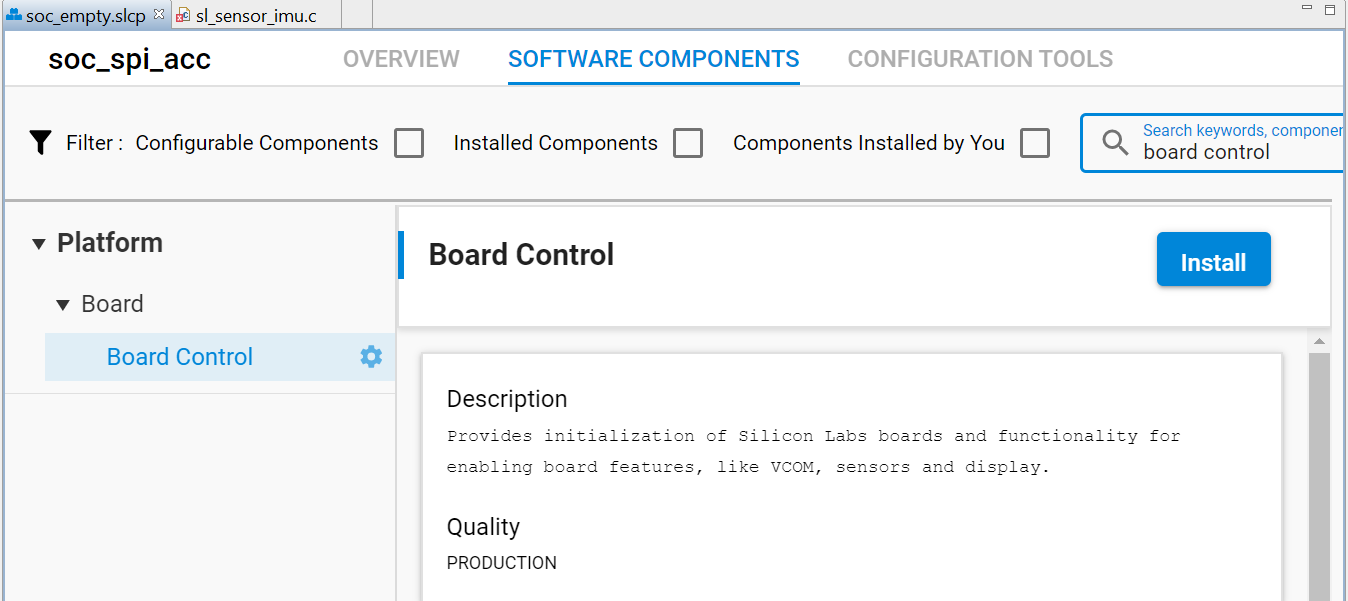
Note: Installing the Inertial Measurement Unit sensor adds sl_sensor_imu.c/h files. These files are dependent on the Board Control. In the future, you will be able to add support for a custom board by adding a Board Control file to the same location where you located the option for the Thunderboard BG22.
Note: Inertial Measurement Unit GATT Service configuration button should link to the btconf->gatt_service_imu.xml. In the future, you will be able to add support for a custom board.
Summary of Previous Steps#
IMU - Inertial Measurement Unit Component#
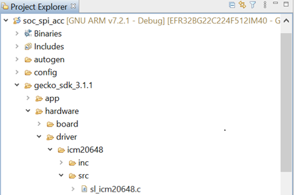
After you add/install the IMU - Inertial Measurement Unit, you will see that files, such as sl_icm20648.c and sl_icm20648.h were added.
Note:
These are driver files prepared by Silicon Labs for ICM-20648. The vendor of the sensor
commonlyprovides this driver. Usually, modifications will need to be made.For example, for ICM-20648, InvenSense provides theSoftware User Guide For ICM-20×48 eMD.
If you use sensors from another vendor, implement a similar driver yourself.
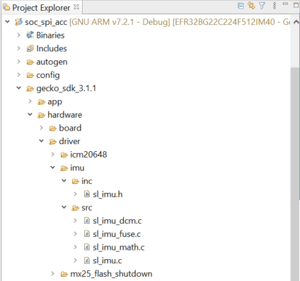
This component also adds the driver files sl_imu_dcm/sl_imu_math.c/sl_imu_fuse.c/sl_imu.c, which are also prepared by Silicon Labs for ICM-20648.
Inertial Measurement Unit sensor Component#
After you add/install the Inertial Measurement Unit sensor, you will see that additional files were added.
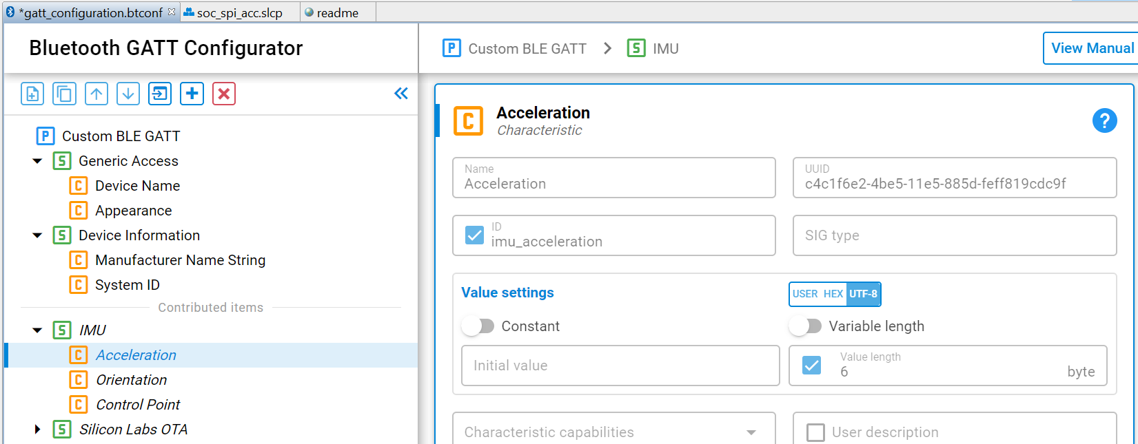
Inertial Measurement Unit GATT Service Component#
After you add/install the Inertial Measurement Unit GATT Service, you will see that additional files were added.
Note: This will add Acceleration and Orientation service.
In the file sl_event_handler.c, you can see the API sl_gatt_service_imu_step was added into the routine sl_internal_app_process_action. This will transmit Acceleration and Orientation data to a client when the client subscribe the service.
void sl_internal_app_process_action(void)
{
sl_gatt_service_imu_step();
}GATT Configuration#
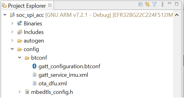
Go back to the
gatt_configuration.btconffile (tab). If you have closed this tab, you can re-open it either viaProject ExplorerorSoftware Components->Advanced Configurators->Bluetooth GATT Configurator.
You can rename the
device nameviaCustom BLE GATT->Generic Access->Device Name->Value settings->Initial value. Here, it is renamed tospi_acc.
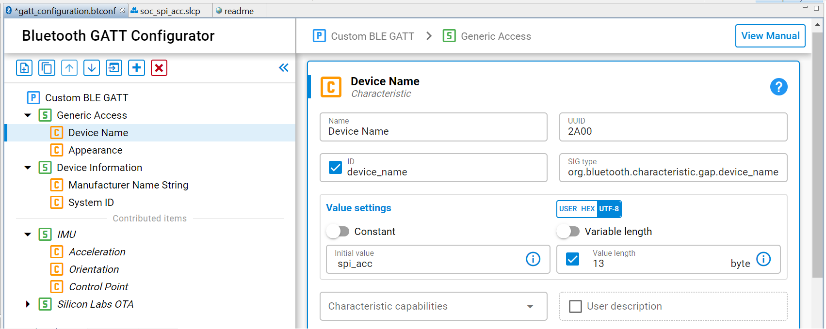
Later in the lab, EFR Connect mobile app will display the
AccelerationandOrientationvalues under their UUIDs. You can write them down to verify which one you are viewing.
Note: You can simplify by recording the first 5 unique characters of the UUID. Accel = c4c1f6; Orient = b7c4b6
Adding the Project Source Files#
Copy the provided app.c file to the top level of the project. The source files and code details are found at the
Code Explanationsection.app.cwill overwrite the existing file to add the new application. The source files can be dragged and dropped into Simplicity Studio or placed in this file path:C:\Users\user_account\SimplicityStudio\v5_workshop\soc_spi_acc
Note: Where user_account is the default workspace and Simplicity Studio installation path. You can also edit the app.c file manually.
Build and Flash the Project#
Build the project by clicking on the
hammericon in the top left corner of the Simplicity StudioIDE perspective.

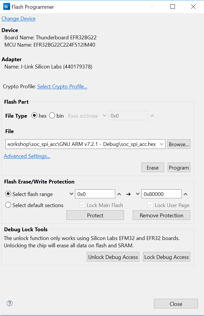
Right-click on the
hexfile (underGNU ARM xxx - DebugorBinaries) and selectFlash to Device...to make theFlash Programmerwindow appear.
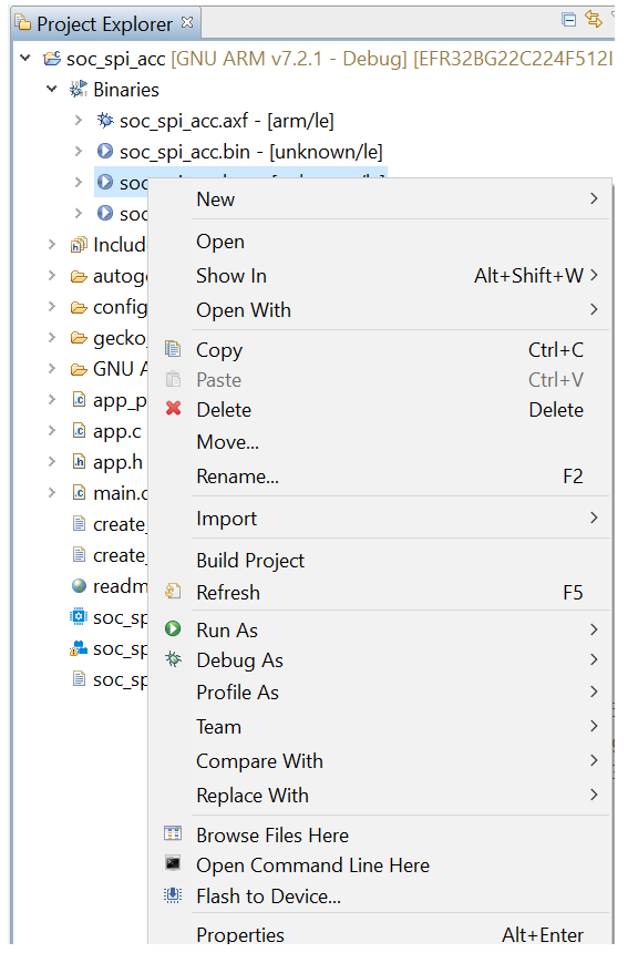
Note: hex image is recommended here rather than bin image. If you choose 'bin', you need explicitly give the base address in the Flash Programmer.
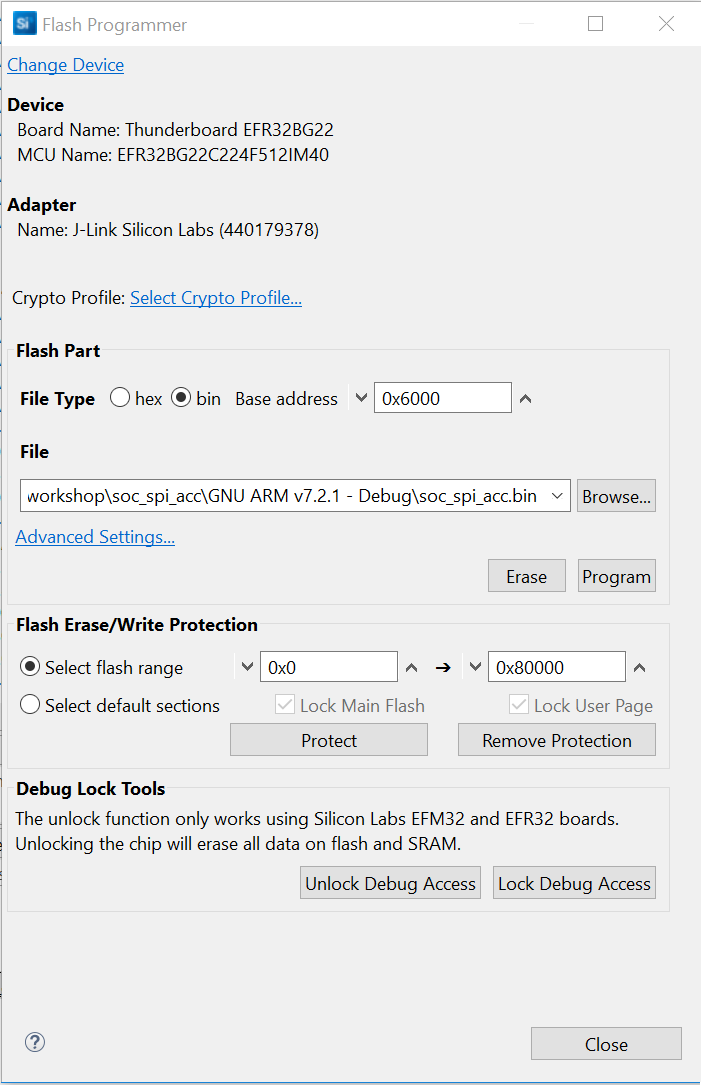
Click
Programto flash the device.
Note: The EFR32BG22 has additional security features and in some cases (i.e., when the board is first plugged in), the tools will prompt to query the Debug Challenge Interface (DCI). Select the connected device and then the link for Click to Query Lock Status. The device target to program text will no longer be grayed out. Then, select OK.
Usage#
Connecting with EFR Connect App#
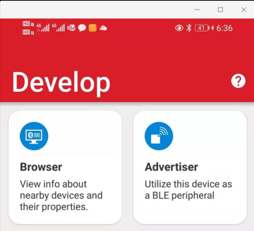
Open the mobile app
EFR Connectand select theDevelop->Browser.
With the
EFR Connect App,Connectto the device.
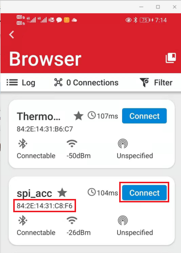
Note: If multiple Bluetooth devices are visible:
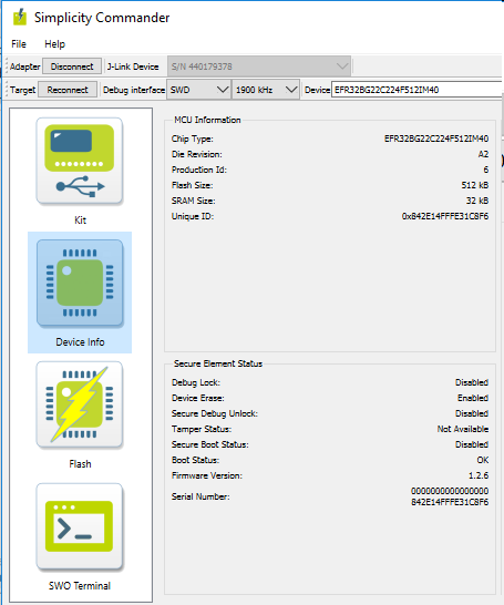
You may try to get the
MACof the device viaSimplicity Commander(Serial Number) first.You may also use
device name(step 18 above) to determine which device to connect to.You may also filter the scanning via
RSSIstrength.
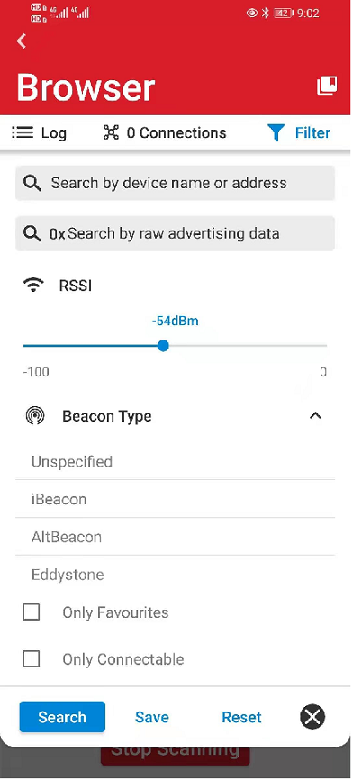
Note: If the board is not found, press the reset button on the kit or click Stop Scanning then Start Scanning in the app.
Click the
Service->Characteristic->Notifybutton. Here, the Service and Characteristic are shown asUnknownbecause they are not standard. Click the 'Notify' bell at the bottom of the Characteristic to let the app (as client)subscribethe service.
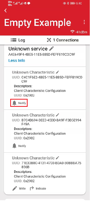
Note: You should already have the UUID in step 19.
You should see the sensor data get updated regularly. You can change the orientation of the Thunderboard or shake it (change acceleration) to see this change.
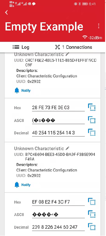
Note: observe “Average” of value in one position. Then, change orientation and you should notice a change in the average value.
Code Explanation#
The following sections explain critical lines of code pertinent to this lab. The code can be found in different files (driver).
Accelerometer (ICM-20648) Driver#
sl_icm20648_config.h#
This is a header file generated automatically by the Simplicity Studio Pintool/Software Component. You may need to change the pin map based on your hardware.
Use the Software Components->Platform->Board drivers->ICM20648 - Motion Sensor->Configure to change it.
The pin map for ICM-20648 is here:
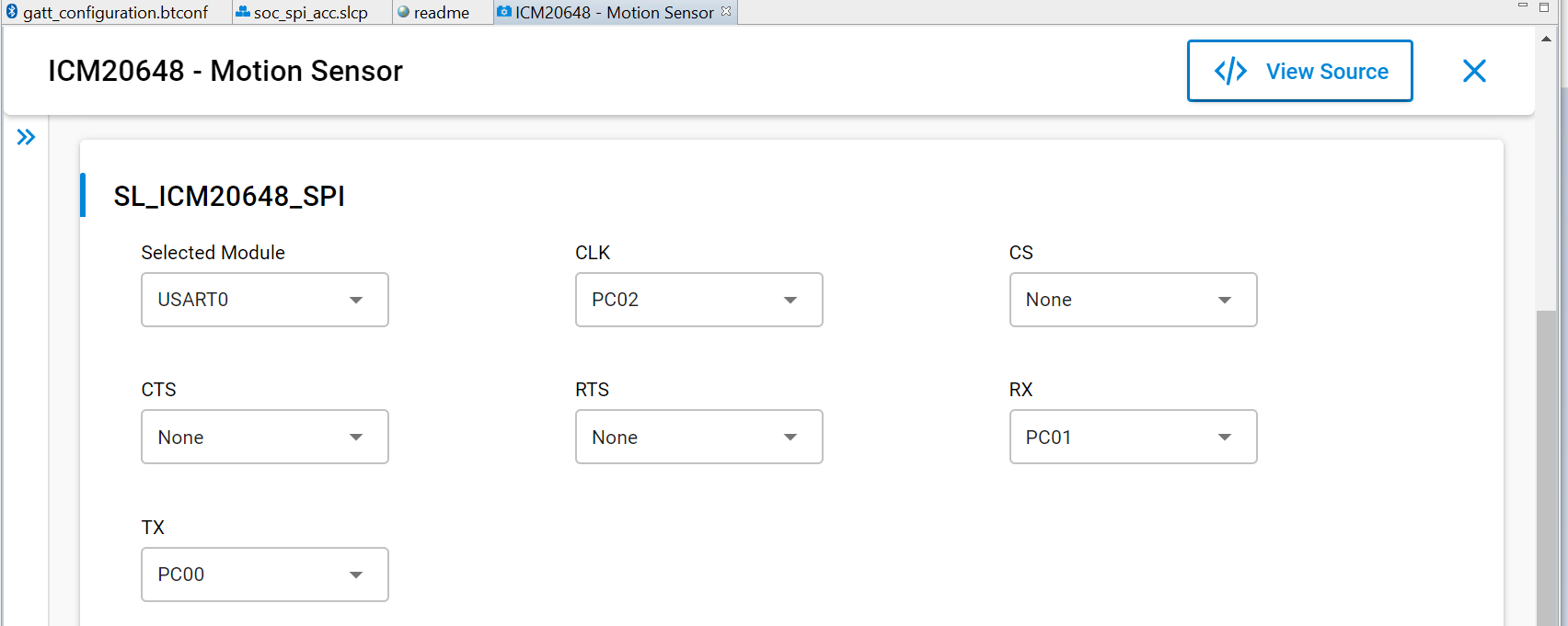
Connection between IMU sensor and EFR32BG22.
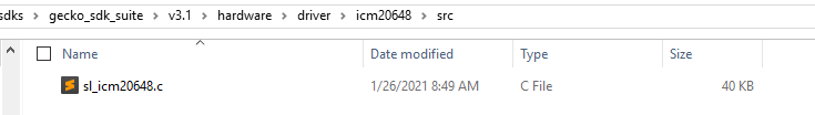
sl_icm20648.c#
This file is located in folder, as follows:
C:\SiliconLabs\SimplicityStudio\v5\developer\sdks\gecko_sdk_suite\v3.1\hardware\driver\icm20648\src
This is the driver file for ICM-20648 sensor prepared by Silicon Labs.
If you use a sensor from another vendor, you may need to consider implementing the similar driver for it. Consider contacting the vendor for help to implement the driver.
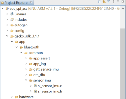
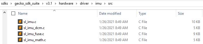
sl_imu_dcm.c/sl_imu_math.c/sl_imu_fuse.c/sl_imu.c/sl_sensor_imu.c#
These files are re-packed of the API provided in the driver sl_icm20648.c. The high-level code (app.c and other) calls APIs, such as sl_sensor_imu_init, sl_sensor_imu_get, and others provided in the file sl_sensor_imu.c/h to initialize, enable/disable the IMU sensor, and read sensor data.
These files are in the following folders:
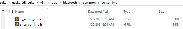
C:\SiliconLabs\SimplicityStudio\v5\developer\sdks\gecko_sdk_suite\v3.1\hardware\driver\imu\src
C:\SiliconLabs\SimplicityStudio\v5\developer\sdks\gecko_sdk_suite\v3.1\app\bluetooth\common\sensor_imu
Note:
sl_sensor_imu.c/hprovides APIs for the app, which are added after installing the componentInertial Measurement Unit sensor.sl_imu_dcm.c/sl_imu_math.c/sl_imu_fuse.c/sl_imu.cwere added after installing the componentIMU - Inertial Measurement Unit.sl_icm20648.cwas added after installing theICM20648 - Motion Sensor. This is a dependency component of theIMU - Inertial Measurement Unit.
Application (app.c)#
The SoC Empty project generates a default app.c source file with a skeleton Bluetooth event handler. The app.c file provided for this lab adds code to handle the BLE connection and notifications.
Connection Opened#
The IMU sensor is initialized and enabled when the event sl_bt_evt_connection_opened_id is received. The IMU sampling does not start until a connection has been made and the user has enabled GATT Acceleration Notification (or Orientation Notification) characteristics.
/* place 1, code added for accelerometer workshop */
static void sensor_init(void)
{
sl_sensor_imu_init();
sl_sensor_imu_enable(true);
}
// -------------------------------
// This event indicates that a new connection was opened.
case sl_bt_evt_connection_opened_id:
/* place 4, code added for accelerometer workshop */
sensor_init();
break;
Connection Closed#
When the connection is closed, the sl_bt_evt_connection_closed_id event is triggered. To save power when no devices are connected, the sensor was disabled via sensor_deinit function.
/* place 2, code added for accelerometer workshop */
static void sensor_deinit(void)
{
sl_sensor_imu_deinit();
}
// -------------------------------
// This event indicates that a connection was closed.
case sl_bt_evt_connection_closed_id:
// Restart advertising after client has disconnected.
sc = sl_bt_advertiser_start(
advertising_set_handle,
advertiser_general_discoverable,
advertiser_connectable_scannable);
sl_app_assert(sc == SL_STATUS_OK,
"[E: 0x%04x] Failed to start advertising\n",
(int)sc);
/* place 5, code added for accelerometer workshop */
sensor_deinit();
break;Sensor Data Read#
The code below placed in app.c will periodically read sensor data.
/* place 3, code added for accelerometer workshop */
sl_status_t sl_gatt_service_imu_get(int16_t ovec[3], int16_t avec[3])
{
return sl_sensor_imu_get(ovec, avec);
}This was called by sl_internal_app_process_action->sl_gatt_service_imu_step.
It overrides the weak routine sl_gatt_service_imu_get in the sl_gatt_service_imu.c.
SL_WEAK sl_status_t sl_gatt_service_imu_get(int16_t ovec[3], int16_t avec[3])
{
(void)ovec;
(void)avec;
return SL_STATUS_FAIL;
}Pay special attention to the variable imu_state in the file sl_gatt_service_imu.c. event sl_bt_evt_connection_closed_id and sl_bt_evt_gatt_server_characteristic_status_id will change its value.
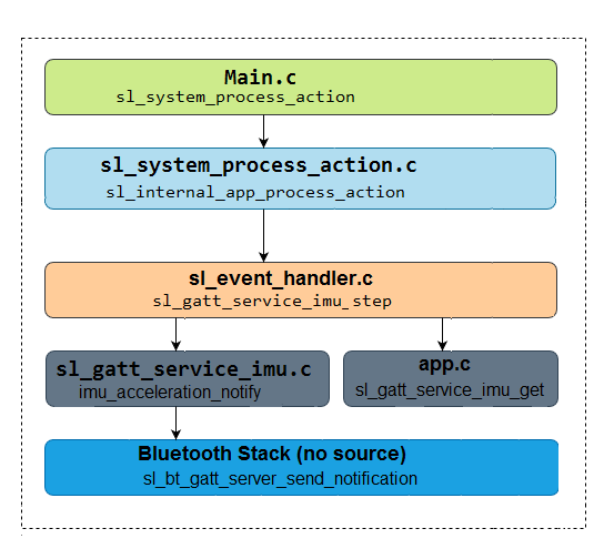
App Code Call Hierarchy#
BLE Notification#
After the user has enabled GATT notifications to the characteristic, the sl_bt_evt_gatt_server_characteristic_status_id event is triggered. In this event, the device will periodically update the characteristic value until the device disconnects.
sl_event_handler.c#
This file was automatically generated and is in the following folder (workspace):
C:\Users\delu\SimplicityStudio\v5_workshop\soc_spi_acc\autogen
void sl_internal_app_process_action(void)
{
sl_gatt_service_imu_step();
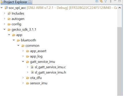
}sl_gatt_service_imu.c#
This file is in the following folder:
C:\SiliconLabs\SimplicityStudio\v5\developer\sdks\gecko_sdk_suite\v3.1\app\bluetooth\common\gatt_service_imu
void sl_gatt_service_imu_step(void)
{
if (imu_state) {
if (SL_STATUS_OK == sl_gatt_service_imu_get(imu_ovec, imu_avec)) {
if (imu_acceleration_notification) {
imu_acceleration_notify();
}
if (imu_orientation_notification) {
imu_orientation_notify();
}
}
}
}This routine calls imu_orientation_notify and imu_acceleration_notify to send the sensor data to the client.
BLE Notification Call Hierarchy#
Source#
Porting Considerations#
Other Sensors#
EFR32BG22 Thunderboard also integrates other sensors:
Silicon Labs Relative humidity & temperature sensor: I2C Si7021
Silicon Labs UV and ambient light sensor: I2C Si1133
Silicon Labs Hall effect sensor: I2C Si7210
If your solution needs these sensors, you may use a similar procedure to add them.
Bootloader#
The application generated via Bluetooth SoC Empty project doesn't include the bootloader.
Program the bootloader to the device first. In some cases, the bootloader may be missing from the device if it has been completely erased. If that happens, do the followingS:
Open the
Flash Programmerand program the bootloader found here:C:\SiliconLabs\SimplicityStudio_v5\developer\sdks\gecko_sdk_suite\v3.1\platform\bootloader\sample-apps\bootloader-storage-internal-single-512k\efr32mg22c224f512im40-brd4182a\bootloader-storage-internal-single-512k.s37Flash a demo example first (like
Bluetooth SoC - Thunderboard EFR32BG22), then flash the application.
IMU Sensor Data Interpretation#
The EFR Connect shows the sensor raw data. To interpret data, see the sensor and driver data sheets. To show a meaningful sensor data, look at the source code of the Thunderboard app.
Reference#
Peripheral Examples Gecko Platform Documentation Simplicity Studio v5 User's Guide