Prerequisites#
This document will go over the hardware and software pre-requisites for building and running a multiprotocol solution locally. Note that this section will be using Raspberry Pi + Raspian OS, however, this is not necessarily required and you can build and run the multiprotocol solution on similar ARM host platforms.
Hardware#
Raspberry Pi 4
SD Card 32GB+
EFR32 Radio Board (For example BRD4180B)
Either: WSTK / WPK (BRD4001 / BRD4002)
PC with Simplicity Studio
Note: For SPI configuration, you can use a Pi Hat Expansion Header BRD8016A in replacement for a WSTK/WPK.
Software#
Linux host OS: The following sections use raspberry Pi OS Lite using Debian Bookworm Version 12
Silicon Labs SDK
For GSDK 4.4.0 and up (Including SiSDK) you can use raspberry Pi OS Lite using Debian Version 12 (Bookworm), which uses GCC v12.2.
Note: Zigbee Specific: Refer to Building Zigbeed & Z3Gateway to find supported Zigbeed platforms.
Install Required Prerequisite Packages#
sudo apt-get update && sudo apt-get upgrade -y
sudo apt-get install cmake git libreadline-dev libmbedtls-dev socat
sudo apt-get install bluetooth bluez bluez-tools rfkill libbluetooth-dev
Some versions of operating systems for the Raspberry Pi have enabled a swapfile. This file creates a lot of unnecessary wear on the SD card and causes performance to degrade drastically over time. It is recommended to disable this with the following commands:
sudo dphys-swapfile swapoff
sudo dphys-swapfile uninstall
sudo apt remove dphys-swapfile
SPI Configuration#
This section is intended only for users running the co-processor with SPI, UART co-processor configurations can skip this section.
Configuring RasperryPi OS to run the SPI Driver#
Open /boot/config.txt and add the following configuration:
# Enable SPI0 with 1 chip select
[all]
dtoverlay=spi0-1cs

# If the CS pin number must be changed, use and adapt this line **instead**:
dtoverlay=spi0-1cs,cs0_pin=8

# If you need two CS pins, use and adapt this line instead:
dtoverlay=spi0-2cs,cs0_pin=8,cs1_pin=7
Reboot for changes to take effect.
sudo rebootValidate that your changes are successful, by running:
ls /dev | grep spi
success will yield the following output:
```bash
spidev0.0
```
To make sure the chip select GPIOs are proper, run: dtc -I fs /sys/firmware/devicetree/base and make sure you can find the following configuration:
spi0_cs_pins{
    brcm,function = <0x01>;
    phandle = <0x0f>;
    brcm,pins = <0x08>;
};
In this configuration the CS pin is connected to GPIO 8 so this is the correct and expected pin configuration of the RasperryPi host.
SPI Pin mapping of Raspberry Pi to Co-Processor#
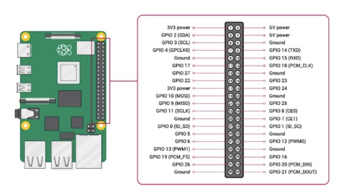
The following pinout diagram shows the GPIO mappings for a RaspberryPi 4:


The following table provides the pin mapping required between the RaspberryPi 4 GPIO, the WSTK Pin out, and the cpcd.conf file:
Pin Name | Pin Tool Mapping | Radio Board Pin | EXP Header Pin | Raspi Config |
|---|---|---|---|---|
IRQ | PB00 | P4 | EXP7 | GPIO22 (Pin 15) |
Bootloader Wake | PB01 | P6 | EXP9 | GPIO24 (Pin 18) |
MOSI | PC00 | P1 | EXP4 | GPIO10 (Pin 19) |
MISO | PC01 | P3 | EXP6 | GPIO9 (Pin 21) |
CLK | PC02 | P5 | EXP8 | GPIO11 (Pin 23) |
CS | PC03 | P7 | EXP10 | GPIO8 (Pin 24) |
Reset | EFR32_Reset | F4 | NA | GPIO23 (Pin 16) |
GND | - | - | EXP1 | Ground (Pin 20) |
Using the WPK: The SPI signals can be manually wired from the WPK EXP pins to the RaspberryPi GPIO. Please note that these signals listed above are using the default cpcd.conf file configuration. If you are using different GPIO pins you will need to modify the various pin configurations in the cpcd.conf file using your text editor of choice. Specifically the MOSI, MISO, CLK, CS, GND pins are all defined by the SPI driver your RaspberryPi is utilizing.
Using the BRD8016A Wireless Expansion board: you will need to mount the expansion board on the RaspberryPi and make sure that the expansion board switch is set to the high power mode. By default, the SPI configuration on the co-processor and CPCD should match this configuration.
