Start a Project#
Simplicity Studio® 5 (SSv5) supports several different project types, which can be created through File > New. These include:
Silicon Labs Project Wizard (creates Project Configurator projects, as described in this section)
Solution... (creates a combination of two or more projects)
Project... (opens the New Project Wizards dialog)
Other (combines all of the above selections with other, rarely used options)
Select Files > New > Project to open the New Project Wizards dialog.
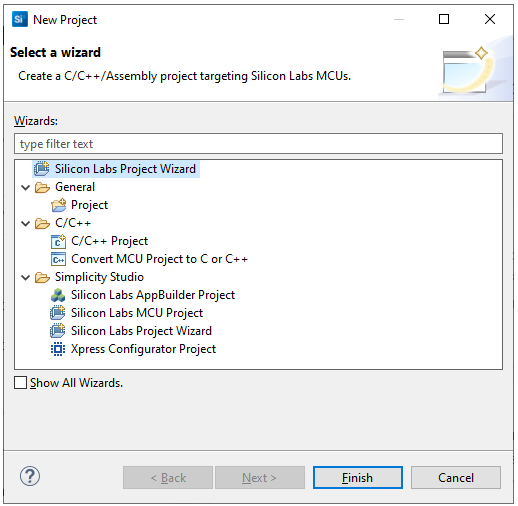
Most notably:
Silicon Labs Project Wizard (two instances) and also Silicon Labs MCU Project Wizard: Creates Project Configurator projects, as described in this section.
AppBuilder Project Wizard: Creates a legacy AppBuilder Project
This page focuses on Project Configurator (*.slcp) projects, as well as Solutions, or combinations of Project Configurator projects. On this page:
Project Creation#
New Simplicity Studio® 5 (SSv5) projects are created through a sequence of three dialogs:
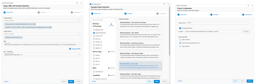
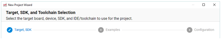
An indicator at the top of the dialog shows you where you are.
You can start a project from three different locations in the Launcher Perspective. Where you start determines which of the three dialogs you will land on. Click BACK to move to an earlier dialog, if you need to make a change.
From the OVERVIEW tab: Click Create New Project. Starts on the Examples dialog.
From the EXAMPLE PROJECTS tab: Use the filters as needed, select a project, and click CREATE. Starts on the Project Configuration dialog.
From the file menu: Select New >> Silicon Labs Project Wizard. Starts on the Target, SDK, and Toolchain Selection dialog.
While you are getting started, you can leave the default values in place.
Target, SDK, and Toolchain Selection#
If you have connected or selected a target, all information is pre-populated. Otherwise you can select target parts here. Click NEXT.
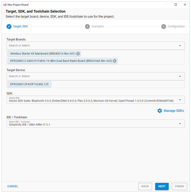
IDE / Toolchain has several options, not all of which are used within the Simplicity IDE. In those cases the project still shows up in the Simplicity IDE Project Explorer view, but you use the IDE for which the project was created to build and debug the project.
Simplicity IDE / GNU ARM vn.n.n: This is the default toolchain used when Simplicity Studio is first installed. The Simplicity IDE is used for all project operations - editing source files, building the project, debugging the project. If multiple version of the GNU ARM Toolchain are installed, there are options for each version.
Simplicity IDE / IAR ARM vn.n.n.n: Similar to the first option, but builds use the IAR ARM toolchain. The IAR ARM toolchain requires installation of IAR Embedded Workbench (EW) external to Simplicity Studio and a license for IAR EW must be purchased from IAR. All project operations are still performed inside the Simplicity IDE.
Makefile IDE (use Simplicity Studio tools to configure and, with a manual step, to debug the project but use 'make' to build the project): This option creates a project without a Simplicity IDE build configuration and [No toolchain] will be reported. Instead, PROJECTNAME.Makefile and PROJECTNAME.project.mak files are created. They are used from a command prompt or terminal prompt with 'make -f PROJECTNAME.Makefile' to build the project. The Project Configurator (.slcp file) can be used to add / configure / remove software components and the various Advanced Configurators, such as Pintool, Bluetooth Gatt Configurator, or ZCL Advanced Platform, can also be used to configure and generate the project. It just cannot be built from within Simplicity Studio. Also the project cannot be automatically debugged within Simplicity Studio. You must manually create a debug configuration that points to the build .out file.
Visual Studio Code: This option allows you to use Visual Studio Code in combination with Simplicity Studio. Use Simplicity Studio to create the initial project and to make project changes with the Component Editor and various Advanced Configurators. Then do all editing, building, and debugging of the project in VS Code. See the Visual Studio Code page for more information.
CMake: This option creates both the Simplicity Studio .slcp file and a CMake build configuration during project generation. It is designed to be built from the command line. It will generate CMake support for both the GCC compiler and the IAR compiler by default, in separate directories. The dependent compiler must be present on the system. Studio can install the GCC compiler. The IAR compiler must be purchased and installed separately. The Project Configurator (.slcp file) can be used to add / configure / remove software components and the various Advanced Configurators, such as Pintool, Bluetooth Gatt Configurator, or ZCL Advanced Platform, can also be used to configure and generate the project.
IAR Embedded Workbench (use Simplicity Studio tools to configure the project but IAR EW to build and debug the project): This option creates a project with the IAR EW projects files but without a Simplicity IDE build configuration and [No toolchain] will be reported. As with the Makefile IDE, the Project Configurator (.slcp file) can be used to add / configure / remove software components and the various Advanced Configurators can also be used to configure and generate the project. After that, double-click the .eww file to launch IAR EW for building and debugging the project. Project options should be set in IAR EW. You cannot use the Simplicity IDE and IAR EW interchangeably. All operations except project configuration should be done in IAR EW.
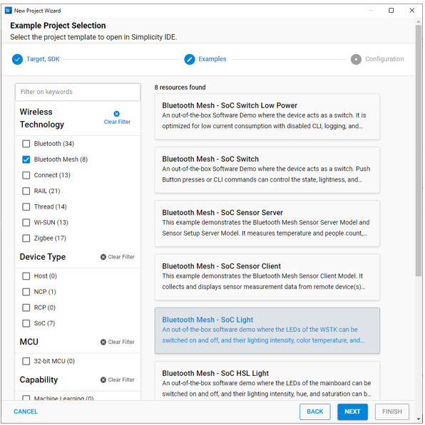
Examples#
Use the checkboxes or keywords to find the example of interest, then select it and click NEXT.
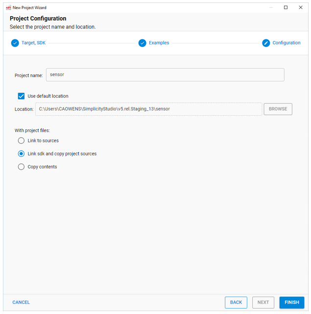
Configuration#
Rename your project if you want. The three selections under "With project files" control which sources are copied and which are linked. If a linked source is modified, the changes apply to any other project linking to that source.
Link to sources: The project links both to the SDK files and to project files such as app.c.
Link SDK and copy project sources (default): Project sources are copied to your workspace. Note that the SDK folder structure is created but if you drill down you will see that all folders are empty.
Copy contents: Both project files and the SDK files are copied to your workspace.
Click FINISH.
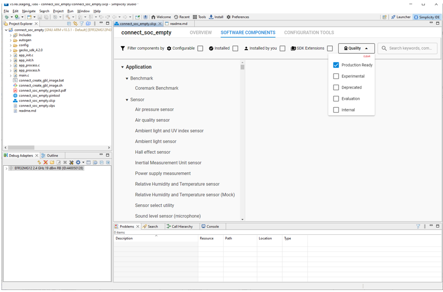
Once you finish project creation, the Simplicity IDE perspective opens. There may be a slight delay for initial configuration. For details on all the features and functions available in this perspective, see About the Simplicity IDE.
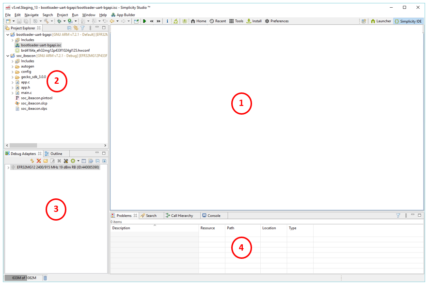
1 - Editor area (depends on the project).
2 - Project Explorer view: Lists the projects and solutions available in your workspace.
3 - Debug Adapters view: Lists the kits or SEGGER J-Links connected to your computer via USB or detected on a local network.
4 - Developer views: A set of views of use during the development process.
The editor in the Simplicity IDE perspective depends on the project:
Project Configurator: Used for all Gecko SDK protocols and tools beginning with Gecko SDK 4.0; Project files end in .slcp.
8-bit Hardware Configurator: Used for 8-bit device applications.
AppBuilder: Legacy tool used for Zigbee EmberZNet and Gecko Bootloader in Gecko SDK 3.2 and lower; Project files end in .isc.
Project Configurator Projects#
As well as introducing Project Configurator projects, this page also introduces
The Pin Tool
Bluetooth and Bluetooth Mesh SDK's GATT Configurator
Bluetooth Mesh SDK's Bluetooth Mesh Configurator
Proprietary SDK's Radio Configurator
Zigbee EmberZNet and Matter SDK's ZCL Advanced Platform
Wi-SUN SDK's Wi-SUN Configurator
Project Configurator projects are defined in .slcp (Silicon Labs Configurator project) files. Users can modify the project by adding, removing, and configuring components on the Software Components tab. See Developing with Project Configurator for details.
NOTE: Beginning with Simplicity Studio version 5.3, you can create a project in the Simplicity IDE by importing an .slcp file. See Import and Export for more information.
The project opens, generally either on a README tab containing an example project description, or on an OVERVIEW tab.
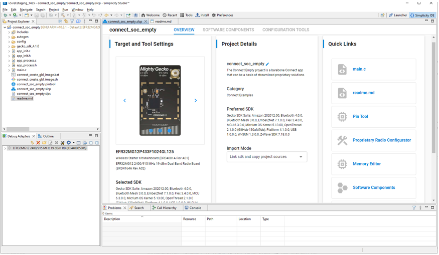
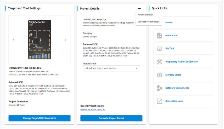
The OVERVIEW tab has three cards with information, some with settings that may be changed:
Target and Tool Settings, where you can change your development target, SDK, and project generators. Scroll down and click Change Target/SDK/Generators to edit these settings. The Project Generators configuration determines the IDE or build system project files that SSv5 generates as you configure your project. (Note: The compiler / toolchain used by Simplicity IDE is configurable in Project > Build Configurations. The default IDE is configurable in Preferences > Simplicity Studio > Preferred IDE.)
Project Details, where you can rename the project, change the project source import mode, generate a project report and, if necessary, force the generation of project and source files (in the autogen folder).
Generate Project Report creates a PDF, available through a link immediately above the control, that provides details on:
Target hardware device
Target hardware device pin mapping
Target SDK
Software extensions used in the build
Installed application, utility, and platform software components
Import mode controls which resources are copied and which are linked. If you modify a linked source, your changes apply to any other project linking to that source.
Force Generation (available through the ... drop-down menu) can be used in rare cases when auto-generation is not triggered, usually because of some change made outside of SSv5 such as editing the .slcp file.
Quick Links provides links to the tools commonly used to modify the project or lower-level configurations such as radio or peripheral connections. The links vary based on the SDK and target device.
To configure the project through the component library, click the SOFTWARE COMPONENTS tab. A number of filters as well as a keyword search are available to help you explore the various component categories. The SDK Extensions filter is only enabled if you have an extension installed. Note that components for all installed SDKs are presented.
Expand a component category\subcategory to see individual components. Components installed in the project are checked (1), and can be uninstalled. Configurable components are indicated by a gear symbol (2).
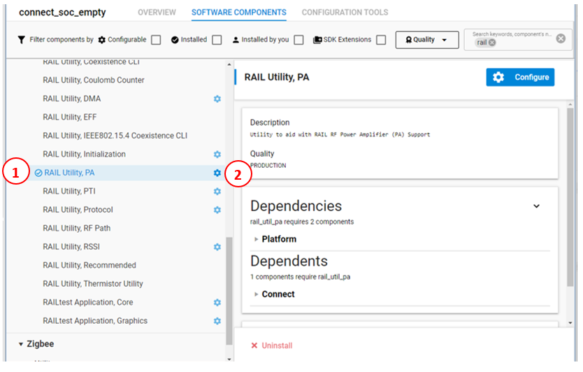
Click the gear symbol next to the component name or Configure in the configurable component description to open the Component Editor. Here you can change parameters or edit the component source directly. You can also go from the component to the Pin Tool
Changes are autosaved in the Component Editor.
As you make changes in the Project Configurator, for example installing or uninstalling a component, project output files are autogenerated. Progress is shown in the lower right of the Perspective.
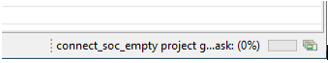
Speed varies depending on your system. Be sure that generation is complete before building the application image.
Build the application image and flash it to your target device as described in Building and Flashing.
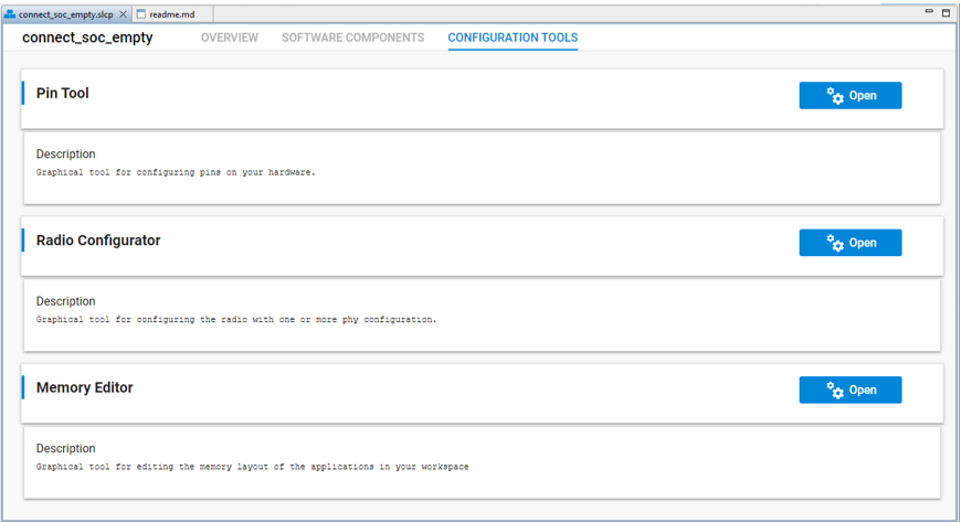
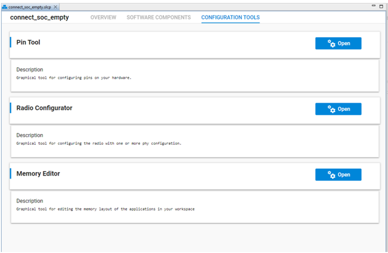
A CONFIGURATION TOOLS tab provides an easy way to open a tool when the tool's tab is not already open, as an alternative to the Quick Links card on the general tab. It shows configuration tools relevant to the project type. For example, a Bluetooth Mesh project shows a number of tools, while an OpenThread project might only show the Pin Tool. Click Open on the tool's card to open it in a separate tab.
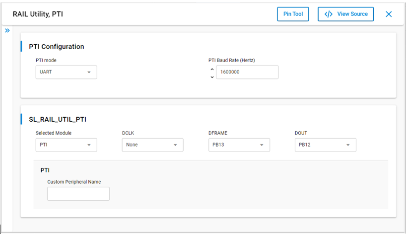
Pin Tool#
The Pin Tool lets you modify the target device's pin use and parameters. As well as opening the Pin Tool through the CONFIGURATION TOOLS tab, you can also double-click the <project>.pintool file in the Project Explorer view.
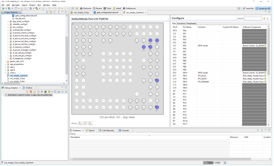
Double-click a Software Component to open the Component Editor and configure that function. Pin Tool does not autosave.
Bluetooth GATT Configurator#
Bluetooth and Bluetooth Mesh projects are also configured with the Bluetooth GATT Configurator.
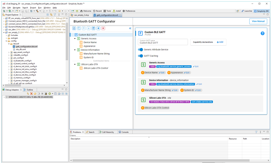
The Bluetooth GATT configurator menu allows you to add and remove services and characteristics.
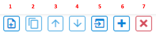
Add an item.
Duplicate the selected item.
Move the selected item up.
Move the selected item down.
Import a Bluetooth GATT database.
Add Predefined.
Delete the selected item.
To add a custom service, click Profile (Custom BLE GATT), and then click Add (1). To add a custom characteristic, select a service and then click Add (1). To add a predefined service/characteristic click Add Predefined (6).
Bluetooth Mesh Configurator#
Bluetooth Mesh project Device Composition Data is configured through the Bluetooth Mesh Configurator. The Device Composition Data is presented in three areas: device information, elements, and models.
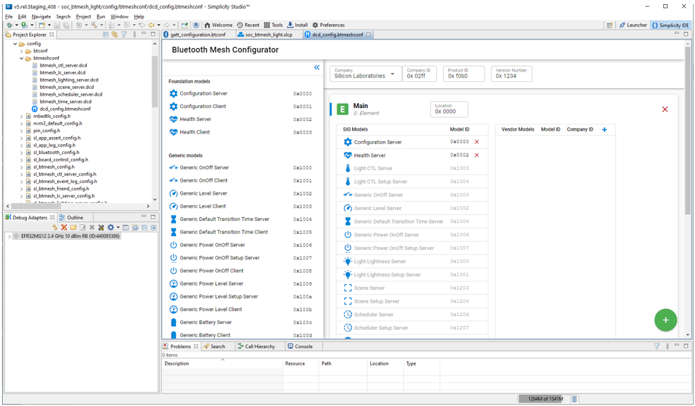
Device information is determined by the company selected in the first field.
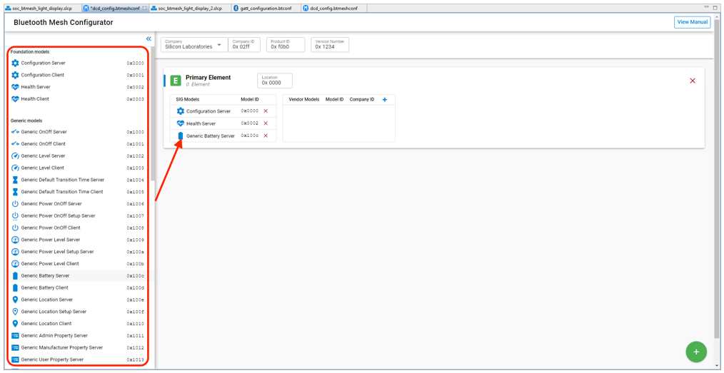
Each node has at minimum a primary element. To add more elements click the green + symbol in the bottom right.
The Bluetooth Mesh Configurator has editors for both SIG-adopted models and vendor models. SIG-adopted model components are provided but cannot be edited. You can, however, delete those models, and then add models to meet your needs. To delete a model, select it and click the red X symbol. To add a SIG-adopted model, drag the model from the left model pool to the SIG Models table in the correct element. A list of all the SIG-adopted models is displayed, and you can choose the one you want.
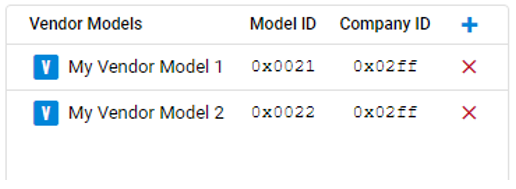
Vendor models give you more flexibility when developing products not covered by the SIG-adopted models. Vendors can define their own specification in these vendor models, including states, messages, and the associated behaviors. The vendor model editor is shown in the following figure.
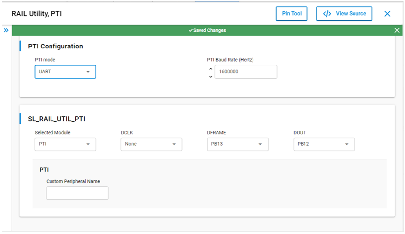
Proprietary Radio Configurator#
The Radio Configurator is provided as part of the Proprietary SDK. Use the Radio Configurator to create standard or custom radio configurations for your RAIL-based radio applications.
The parameters in the Radio Configurator are arranged in cards, some of which are grouped together. Different radio profiles offer different views and parameter sets.
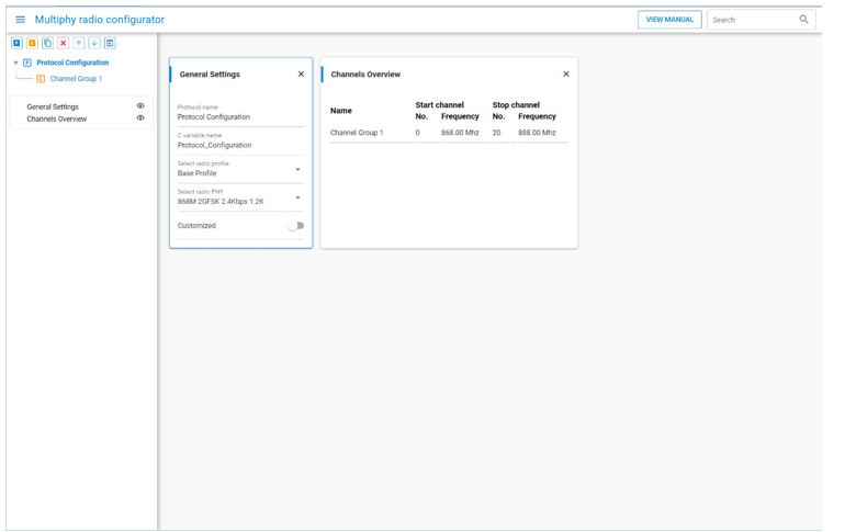
In the General Settings card, select a radio profile in the Select radio profile drop-down menu. A radio profile may be any supported radio link technology. These technologies can be bound by standards (for example the Sigfox or WMBus protocols) or can be fully customized. The fully customizable profile is called the "Base Profile".
Select a radio PHY (radio configuration) in the Select a radio PHY dropdown list. Each profile has "built-in" configurations ready to use.
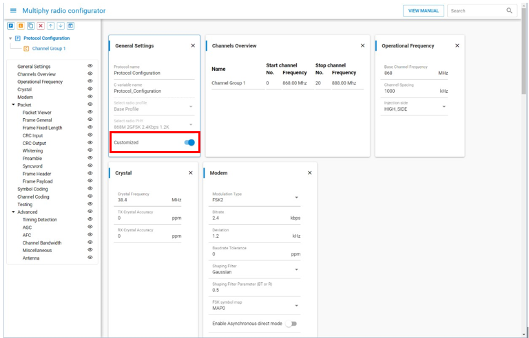
Review and update the profile options. By default, no changes are allowed; fields are grayed out. To enable customization, use the Customized switch on the General Settings card. This allows access to all the parameters defined by the profile.
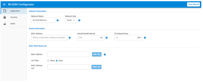
Wi-SUN Configurator#
The Wi-SUN Configurator is provided as part of the Wi-SUN SDK. Use it to configure the main settings of the Wi-SUN application through three panels: Application, Security, and Radio. For some projects only the Radio panel is available. The Wi-SUN Configurator tab is available when a project is created or can be displayed by opening the project file /config/wisun/wisun_settings.wisunconf.
ZCL Advanced Platform#
The ZCL Advanced Platform (ZAP) is provided as a configuration tool for both Zigbee and Matter projects. Use it to manage endpoints, clusters, and commands.
The interface, which differs slightly for Matter and Zigbee, is based on adding or modifying endpoints. Click an endpoint to open the configuration editor.
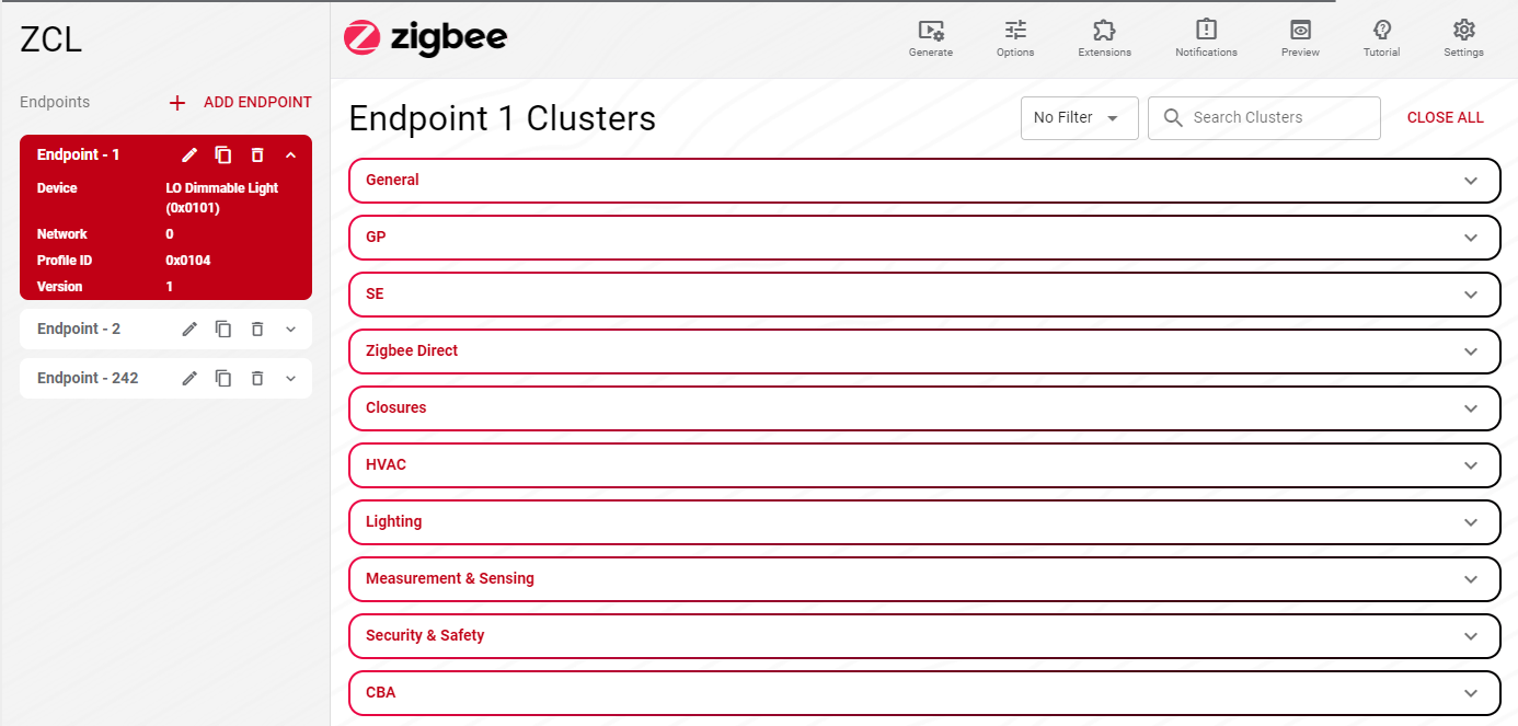
You can add and configure clusters as needed. Configuration changes made through the Zigbee Cluster Configurator for a Zigbee project are saved to <project-folder>\config\zcl\zcl_config.zap. For a Matter project the configuration is saved to <project-folder>\config\zap\<name>.zap. When you save the file, the Zigbee Cluster Configurator not only saves the .zap file into your project, but also automatically generates all the files required for your application.
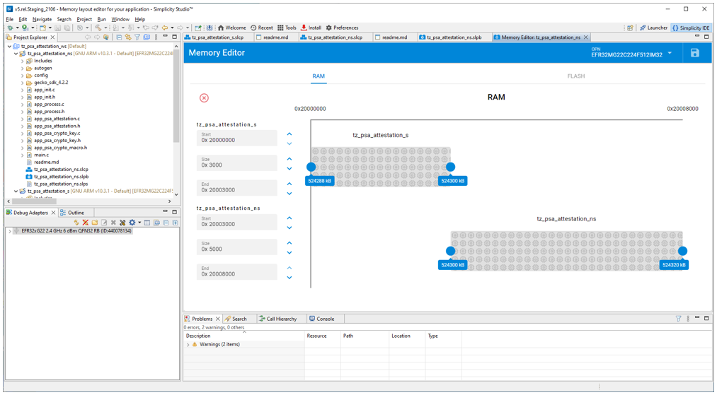
Solutions#
A Solution is a combinations of projects that can be compiled, debugged, and flashed together. Solutions are also called workspaces in some contexts. The projects in a solution can be configured individually. When the solution is built, the Post-Build Editor is used to combine the project images into a single downloadable .s37 image. Applications that make use of the Series 2 TrustZone feature use solutions to combined the secure and non-secure TrustZone projects. Solutions can also be used to debug an application and its bootloader together.
The Memory Editor is a graphical tool for editing the flash and RAM memory layout of the applications in a solution. Not all example projects have default settings included at this time, which results in a warning when you open the editor. Save the default values that the tool calculates as your starting point.
AppBuilder Projects#
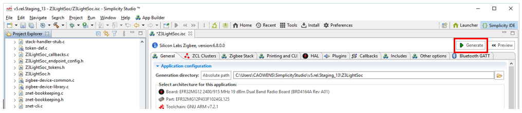
AppBuilder Projects are configured by modifying parameters in various tabs, especially the PLUGINS tab. See Developing with AppBuilder for details.
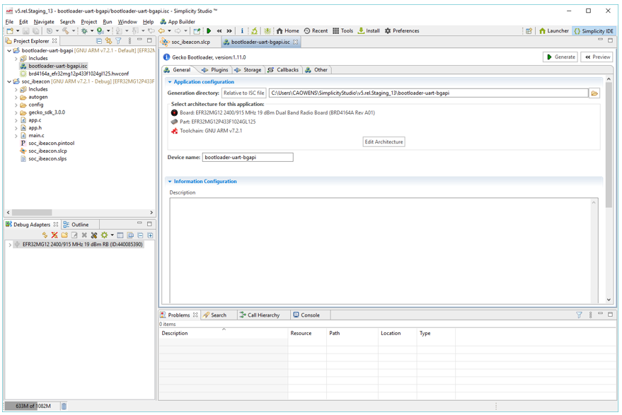
When you have configured the project, click Generate to create project files. Build the application image and flash it to your target device as in Building and Flashing.
To modify the target device's pin use and parameters, use the Hardware Configurator available on the HAL tab. Note that, although the interface is similar to the 8-bit Hardware Configurator, this is a different tool.
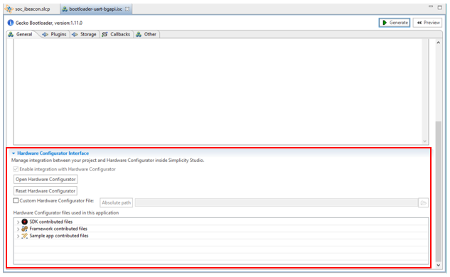
Changes made through the Hardware Configurator are stored in a board-specific .hwconf file.