General Serial Peripheral Interface (GSPI) Initialization and Configuration#
Overview#
The SiWx917 General Serial Peripheral Interface (GSPI) peripheral provides a high-performance SPI interface with configurable clocking, data width, chip-select handling, and optional DMA acceleration. This guide targets the GSPI primary instance in standard single-data-line mode.
Startup Sequence#
This section describes how to initialize the GSPI peripheral for high-performance SPI communication, including project setup using Simplicity Studio.
Hardware and Software Requirements#
Hardware requirements:
Windows PC
Silicon Labs Si917 Evaluation Kit: WPK (BRD4002) with one of the following radio boards: BRD4338A, BRD4342A, or BRD4343A
SiWx917 AC1 Module Explorer Kit: BRD2708A
Software requirements:
Simplicity Studio (latest version)
Serial console setup
For serial console setup instructions, see Console input and output.
Typical GSPI Setup Diagram#
The following diagram shows a typical hardware setup for connecting the SiWx917 GSPI peripheral to an external SPI device:

Figure: Example GSPI wiring between SiWx917 and a high-speed peripheral device.
Note: Ensure that the GSPI signals (CLK, CS, MOSI, MISO) are mapped to the correct GPIO pins as per your board configuration.
Getting Started with Simplicity Studio#
Install Simplicity Studio: Download and install the latest version from the Silicon Labs website.
Connect hardware: Plug in the SiWx917 evaluation or module explorer board by USB and power it on.
Launch Simplicity Studio: Open the IDE and make sure your board is detected.
Create a new project:
Select your detected SiWx917 board (or target device).
In the Examples view, search for
GSPI.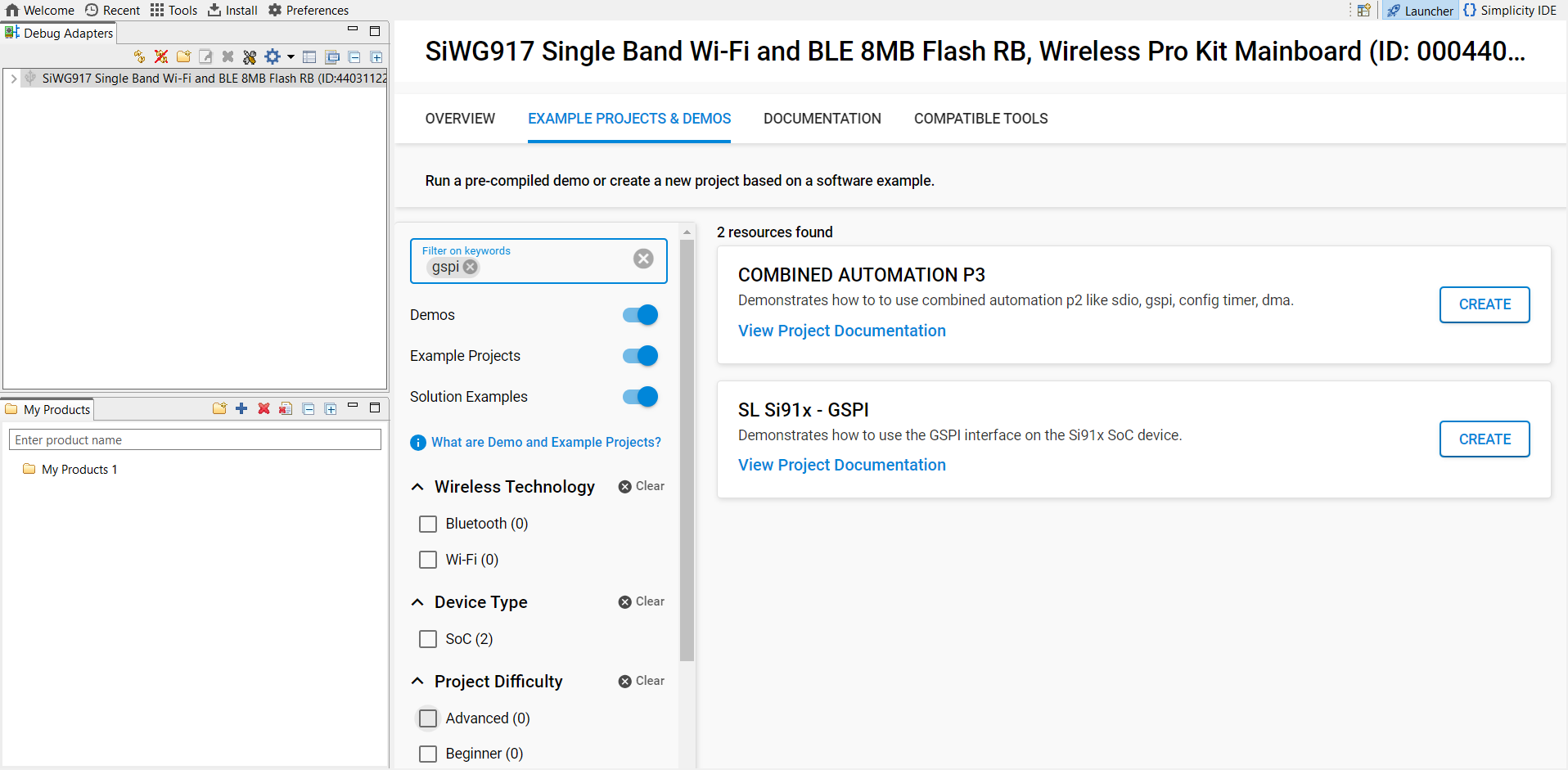
Select an appropriate GSPI example (for example, GSPI Primary) from the WiSeConnect SDK.
Click Create and set the project name, location, and whether to link or copy SDK sources.
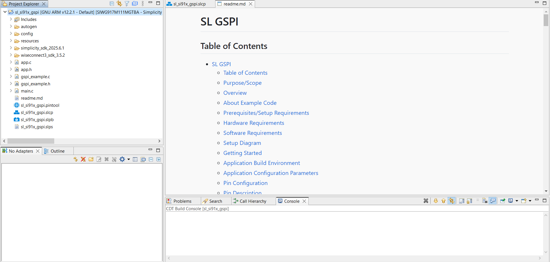
When the project is generated, Simplicity Studio opens the README, and you can review the auto-created structure.
Read the example documentation to understand the initialization flow, configurable parameters, and how to adapt it for your secondary SPI device.
Build and flash: Compile the project and flash it to your board.
For more details, see Using the Simplicity Studio IDE.
For a complete example and project setup, see the Silicon Labs GSPI Peripheral Example Project.
This startup sequence ensures your GSPI peripheral is correctly initialized for both standard and advanced SPI modes, supporting reliable communication in your embedded application.
GSPI Example Folder Structure#
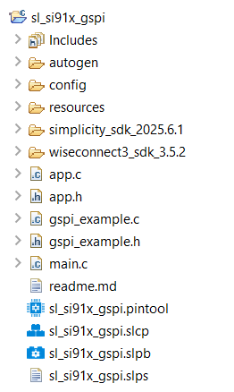
Folder and file descriptions:
autogen/: Contains files automatically generated by Simplicity Studio, such as configuration headers and linker scripts.config/: Holds platform-specific configuration header files.resources/: Includes example resources, such as images used in documentation.simplicity_sdk/: Contains the Simplicity SDK (Gecko SDK) platform layer and third-party libraries.platform/: Provides hardware abstraction layer (HAL), CMSIS RTOS, and common libraries.
wiseconnect3_sdk_4.0.0/: Contains WiSeConnect SDK components and resources.components/: Includes modules for Wi-Fi, BLE, Si91x MCU subsystem, and more.
sl_si91x_gspi.slcp: Main Simplicity Studio project file that stores configuration, components, and project metadata.sl_si91x_gspi.slps: Project set file for referencing multiple.slcpprojects, useful for organizing related solutions.sl_si91x_gspi.pintool: Pin Tool configuration file for GSPI peripheral pin assignments.app.c: Main application source file.app.h: Header file for the main application.main.c: Application entry point and startup code.gspi_example.c: Example source file demonstrating GSPI initialization, configuration, and a basic data transfer.gspi_example.h: Header file declaring functions and data structures used ingspi_example.c.readme.md: Documentation and usage instructions for the example.
UC Configuration#
The GSPI peripheral can be configured using Simplicity Studio's Universal Configurator (UC), which provides a graphical interface for setting up GSPI parameters and pin assignments.
To add, view, and configure the GSPI component in your project:
Open your project's
.slcp(Simplicity Studio Component Project) file in Simplicity Studio.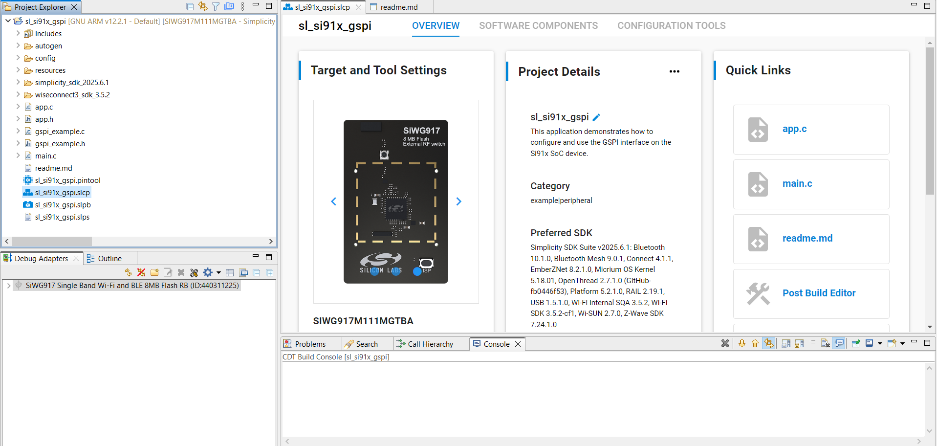
2. Go to the Software Components tab.
3. Search forgspior browse under WiSeConnect3 SDK > Device > Si91x > MCU > Peripheral.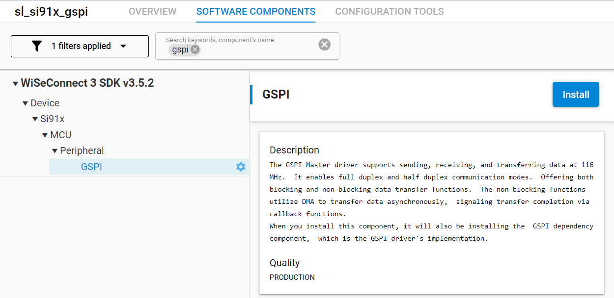
4. Locate the GSPI component. If it is not already installed, click Install.
5. Finish the installation.
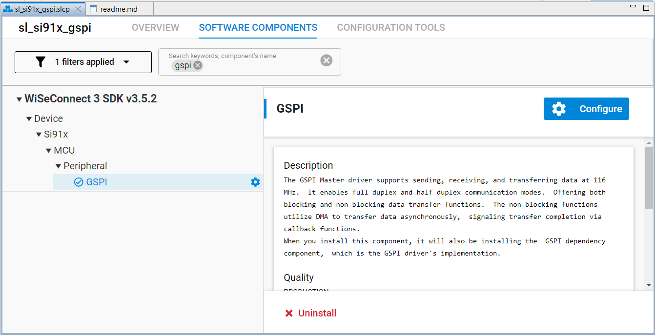
After installing the component:
Click Configure beside the GSPI component to open its parameter UI.
2. Adjust Clock Mode, Bit Rate, Data Width, Byte-wise Swapping (Read/Write), DMA Enable, and pin assignments.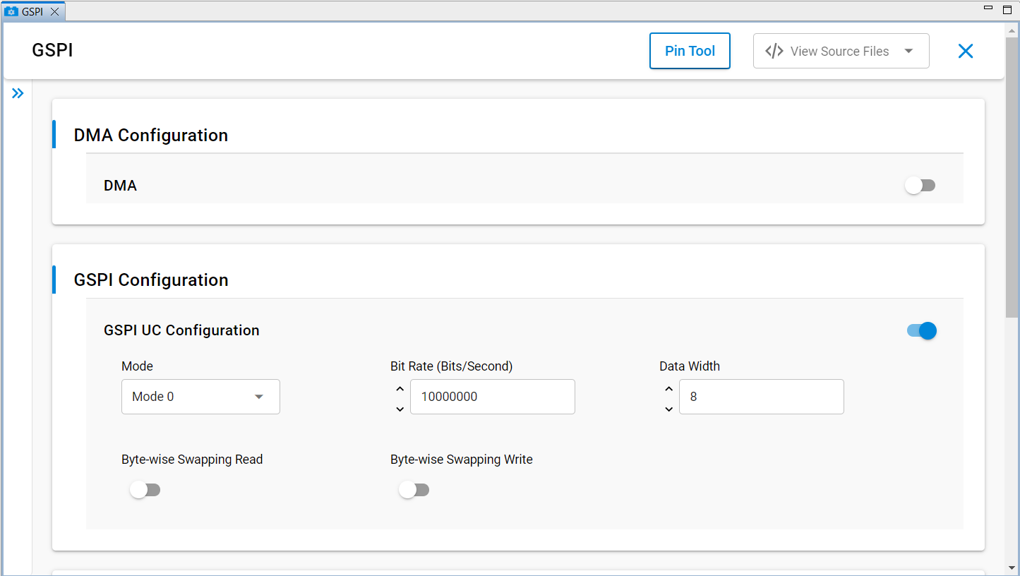
3. Save to regenerate auto-config headers.
Alternatively, you can manually edit the generated configuration header files:
sl_si91x_gspi_primary_config.hsl_si91x_gspi_primary_common_config.h
These files are located in your project's `config/` directory.The following are the available methods for selecting pins in the UC graphical interface:
Dropdown selection: Choose from a list of available pins using the dropdown menu.
Pin Tool selection: Click directly on the Pin Tool map and select an available GPIO.
GSPI Configuration Parameters#
Parameter | Description | Options / Range |
|---|---|---|
Enable GSPI | Enables or disables the GSPI instance | 1 (Enabled), 0 (Disabled) |
DMA Enable | Enables DMA for GSPI transfers | On, Off |
Mode | SPI clock polarity and phase mode | Mode 0, Mode 3 |
Bit Rate | Serial clock frequency (Hz) | 1 – 116,000,000 |
Data Width | Number of bits per data frame | 1 – 16 |
Byte-wise Swapping Read | Enables byte-wise swapping on read operations | On, Off |
Byte-wise Swapping Write | Enables byte-wise swapping on write operations | On, Off |
Slave Select Outputs | Number of Secondary select outputs available (Primary only) | 1 – 3 |
CS0_, CS1_, CS3_ | Chip select signals, configurable via Pin Tool or UC | Assignable GPIO pins |
MISO_, MOSI_, SCK_ | SPI data and clock signals, configurable via Pin Tool or UC | Assignable GPIO pins |
Configurable Parameters and Default Values#
Default configuration values:
Enable GSPI: 1 (Enabled)
Mode: Mode 0
DMA Enable: Off
Bit Rate: 10,000,000 Hz (10 MHz)
Data Width: 8 bits
Byte-wise Swapping Read: Off
Byte-wise Swapping Write: Off
GSPI Pin Annotation#
The GSPI peripheral signals can be mapped to multiple GPIO pins, allowing flexible hardware design. The following table lists the available pin options for the GSPI interface:
GSPI Pin Options#
GSPI Signal | SoC GPIOs |
|---|---|
GSPI_CLK | GPIO_8, GPIO_25, GPIO_46, GPIO_52 |
GSPI_CS0 | GPIO_9, GPIO_28, GPIO_49, GPIO_53 |
GSPI_CS1 | GPIO_10, GPIO_29, GPIO_50, GPIO_54 |
GSPI_CS2 | GPIO_15, GPIO_30, GPIO_51, GPIO_55 |
GSPI_MISO | GPIO_11, GPIO_26, GPIO_47, GPIO_56 |
GSPI_MOSI | GPIO_6, GPIO_12, GPIO_27, GPIO_48, GPIO_57 |
Pin assignment guidelines:
Use pins with good signal integrity characteristics for high-speed operation.
Make sure pins are not conflicting with other peripheral assignments.
Consider PCB routing and length matching for optimal performance.
For detailed information on pin multiplexing, electrical characteristics, and restrictions, see the SiWx917 data sheet.
Configuration Structure#
Populate a configuration structure before calling the configuration API (or rely on UC-generated defaults and override selectively):
typedef struct {
boolean_t swap_read; ///< true to enable and false to disable swap read
boolean_t swap_write; ///< true to enable and false to disable swap write
uint8_t bit_width; ///< Bit width, from 1-16 bits
uint32_t clock_mode; ///< Clock mode, either Mode 0 or Mode 3 of GSPI
uint32_t slave_select_mode; ///< Secondary select mode, either software or hardware output
uint32_t bitrate; ///< Bitrate for setting the clock division factor
} sl_gspi_control_config_t;For the authoritative definition of sl_gspi_control_config_t and the latest parameter descriptions, see the GSPI API reference:
sl_gspi_control_config_t Structure Reference: https://docs.silabs.com/wiseconnect/latest/wiseconnect-api-reference-guide-si91x-peripherals/sl-gspi-control-config-t
API to Initialize#
The GSPI peripheral initialization follows a standard sequence:
#include "sl_si91x_gspi.h"
void gspi_example_init(void)
{
sl_gspi_handle_t gspi_handle;
sl_gspi_config_t config = {
.clock_mode = SL_GSPI_MODE_0,
.bit_rate = 10000000,
.data_width = SL_GSPI_DATA_WIDTH_8,
.slave_select_mode = SL_GSPI_MASTER_HW_OUTPUT,
.swap_read = false,
.swap_write = false
};
// Initialize GSPI as Primary
if (sl_si91x_gspi_init(SL_GSPI_MASTER, &gspi_handle) != SL_STATUS_OK)
return;
// Configure GSPI parameters
if (sl_si91x_gspi_set_configuration(gspi_handle, &config) != SL_STATUS_OK)
return;
// (Optional) Register event callback
sl_si91x_gspi_register_event_callback(gspi_handle, callback_event);
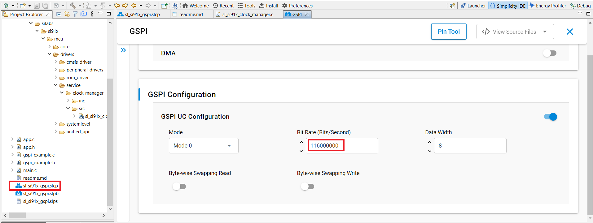
}Achieving 116 MHz GSPI Operation#
To configure the GSPI peripheral for 116 MHz operation, follow these steps:
1. Update INTF PLL Clock Frequency#
Normal application (without Power Manager):
Open
sl_si91x_clock_manager.clocated at:
wiseconnect/components/device/silabs/si91x/mcu/drivers/service/clock_manager/src/Change the INTF PLL clock value from
160000000to116000000.
Power-save application:
Open
sli_si91x_clock_manager.cin the same directory.Update
PS4_PERFORMANCE_MODE_INTF_FREQfrom160000000to116000000.
2. Set GSPI Bit Rate in UC#
In Simplicity Studio's Universal Configurator (UC), set the GSPI Bit Rate parameter to
116000000Hz.
3. Impact on Other Peripherals#
Changing the INTF_PLL frequency affects other peripherals as shown below:
GSPI Source Clock/Div | QSPI (Flash, PSRAM) Max Freq (80 MHz) | Processor Max Freq | Tradeoff |
|---|---|---|---|
INTF_PLL = 116 MHz, Div = 1 | 58 MHz (INTF_PLL/2) | 180 MHz (SOC_PLL) | Flash performance limited to 58 MHz from 80 MHz |
Note: Make sure all connected peripherals can operate reliably at the new clock frequencies.