Wi-Fi PER Mode#
SiWx91x RCP driver supports Wi-Fi PER mode transmit and E2E mode receive functionality. Follow the steps below to verify both functionalities.
PER Transmit#
See the Compilation Steps section and compile the driver, as follows:
# make clean; makeNavigate to the release folder and run the following commands to set the driver to PER mode.
# cd release # insmod rsi_91x.ko dev_oper_mode=1 driver_mode_value=2 rsi_zone_enabled=0x601 # insmod rsi_sdio.ko sdio_clock=10Run the following command to check 11N PER transmit:
# ./transmit <base_interface> <Transmit_power> <Data_rate> <Pkt_length> <Transmit_mode> <Channel_no> <11ax_enable> <Rate_flags> <Aggr_enable> <no_of_packets> <delay> <Regulatory_domain>
Description of each field:
SI No | Parameters | Description | values |
|---|---|---|---|
1 | base_interface | Interface Name (string like rpine0). | |
2 | Transmit_power | Controls the transmit power in dBm units | -7 to 18 127 → The packet will be transmitted at the maximum power from the Transmit power table |
3 | Data_rate | Set the transmit data rate | 1, 2, 5.5, 11, 6, 9, 12, 18, 24, 36, 48, 54, mcs0, mcs1, mcs2, mcs3, mcs4, mcs5, mcs6 and mcs7 |
4 | Pkt_length | Transmit packet length in bytes | |
5 | Transmit_mode | Burst or Continuous mode | 0 → Burst mode 1 → Continuous mode |
6 | Channel_no | Channel number on which packets are transmitted | IEEE802.11 channels |
7 | 11ax_enable | Enable / Disable 11ax mode | 1 → 11ax mode enabled 0 → 11n Mode enabled |
8 | Rate_flags | - To enable/disable Short GI & Greenfield. - Also to set the channel width of the transmitted packets | Bit 0 (Short_GI for HT mode)/(Short_preamble in 11b) Bit 1 : (GreenField for HT mode)/(preamble enable for 11b) Bit 4-2 : CH_BW flags Bit 5 : This bit has to be set when the user selects 11J channel Bit 15-6 : Reserved |
9 | Aggr_enable | Enable / Disable Aggregation of transmitting packets | 0 → Disable 1 → Enable |
10 | no_of_packets | - Number of packets to be transmitted in Burst mode. - The transmission stops after the no. of packets specified by this parameter are transmitted in the Burst mode. - If this value is 0, then the transmission will not stop until the user gives the "./transmit 0" command in order to stop the transmissions. - This parameter is ignored in the case of Continuous mode of transmission. | |
11 | delay | - To specify a delay (in us) between any two packets in burst mode. - If 0, then the packets will be transmitted without any delay. - Is ignored in the case of Continuous mode of transmission | |
12 | Regulatory_domain | Set the regulatory Domain | 0 → US (FCC) 1 → Europe (ETSI) 2 → Japan (JP) 255 → World Domain |
Example
# ./transmit rpine0 127 5.5 750 0 11 0 0 0 0 0 255The above command starts continuous transmission with the following configuration:
Parameter | Value |
|---|---|
Transmit gain | 2 dbm |
Data rate | 5.5 Mbps |
Packet Length | 750 bytes |
Transmit mode | 1 (continuous mode). |
Channel number | 11 |
External PA | disabled |
Rate flags | 1 (Short GI is enabled with 20 MHz Channel width) |
Aggregation | disabled (ignored in continuous mode) |
Number of packets to be transmitted | 0 (ignored in continuous mode) |
Delay between the packets | 0 (ignored in continuous mode) |
Run the following command to check 11AX PER transmit:
# ./transmit <base_interface> <Trasmit_power> <Data_rate> <Pkt_length> <Transmit_mode> <Channel> <11ax_en> <Rate_flags> <Aggr_enable> <no_of_packets> <delay> <Regulatory_Domain> <coding_type> <nominal_pe> <he_ppdu_type> <beam_change> <BW> <UL_DL> <STBC> <Tx_BF> <GI_LTF> <DCM> <NSTS_MIDAMBLE> <spatial_reuse> <BSS_color> <HE_SIGA2_RESERVED> <RU_ALLOCATION> <N_HELTF_TOT> <SIGB_DCM> <SIGB_MCS> <USER_STA_ID> <SIGB_COMPRESSION_FIELD> <USER_IDX>
Description of each parameter is as below:
Parameters Name | Description | Expected Values |
|---|---|---|
coding_type | Indicates whether BCC or LDPC to be used | 0 - BCC 1 - LDPC |
nominal_pe | Indicates Nominal T-PE value | 0 - 0us 1 - 8us 2 - 16us |
HE_PPDU_TYPE | 0 - HE SU PPDU 1 - HE ER SU PPDU 2 - HE TB PPDU 3 - HE MU PPDU | |
Beam Change | Indicates the spatial mapping of pre-HE and HE fields | 0 - pre-HE and HE fields are spatially mapped in the same way 1 - pre-HE and HE fields are spatially mapped differently |
BW | Indicates the BW for the PPDU | SU PPDU: 0 - 20 MHz 1 - 40 MHz 2 - 80 MHz 3 -160 MHz (Only 20 MHz is supported in H/W) ER SU PPDU: 0 - 242-tone RU 1 - upper 106-tone RU |
UL_DL | Indicates whether the PPDU is UL/DL | Set to 1,if PPDU is Sent by Station to AP Set to 0,if PPDU is sent by AP |
STBC | Indicates whether STBC is used for PPDU transmission | 0 - no STBC 1 - STBC only if DCM field is set to 0 |
TxBF | Indicates whether beamforming matrix is applied to the transmission | 0 - No beamforming matrix 1 - beamforming matrix. Set to "0" by default. |
GI_LTF | Indicates the GI and LTF size | SU/ER_SU: 0 - 1x HE-LTF and 0.8us GI 1 - 2x HE-LTF and 0.8us GI 2 - 2x HE-LTF and 1.6us GI 3 - 4x HE-LTF and 0.8us GI if both DCM and STBC fields are 1, else 4x HE-LTF and 3.2us GI MU: 0 - 4x HE-LTF and 0.8us GI 1 - 2x HE-LTF and 0.8us GI 2 - 2x HE-LTF and 1.6us GI 3 - 4x HE-LTF and 3.2us GI TB: 0 - 1x HE-LTF and 1.6us GI 1 - 2x HE-LTF and 1.6us GI 2 - 4x HE-LTF and 3.2us GI 3 - Reserved |
DCM | Indicates whether DCM is applied to Data Symbols | 0 - no DCM 1 - DCM |
NSTS_MIDAMBLE | Indicates the Nsts and Midamble Periodicity | If Doppler is set to 0 BIT[15:13] = Number of space-time streams-1 If Doppler is set to 1 BIT[14:13] = = Number of space-time streams-1 BIT[15] = 0 for MIDAMBLE Periodicity of 10 BIT[15]= 1 for MIDAMBLE Periodicity of 20 Default Doppler value is 0. |
Spatial Reuse | Indicates whether spatial reuse is allowed during the transmission of the PPDU | |
BSS color | Color value of BSS | |
HE_SIGA2_RESERVE | This should be set to 1 | The value should be between 0 to 511 |
RU_ALLOCATION | Indicates the RU Allocation Subfield for 20 MHz BW | The value should be between 0 to 255 |
N_HELTF_TOT | Indicates the number of HE-LTF to be transmitted | The vale should be between 0 to 7 |
SIGB_DCM | Indicates whether DCM is applied to SIG-B Symbols** | The value should be 0 to Enable and 1 to Disable |
SIGB_MCS | Indicates the MCS for SIG-B Symbols | Range of 0-5 6,7 - Reserved |
USER_STA_ID | Indicates the Station ID of the intended user | The value should be between 0 to 2047 |
SIGB_COMPRESSION_FIELD | The value should be 0 or 1 | |
USER_IDX | Indicates the index of the intended user | 0 - 1st user 1 - 2nd user ..... 8 - 9th user 9 - 63 - Reserved |
Example:
# ./transmit rpine0 127 mcs0 4000 0 6 1 0 1 0 0 255 0 2 0 0 0 0 0 0 3 0 0 0 0 0 0 0 0 0 0 0 0Run the following command to stop PER transmit:
# ./transmit rpine0 0Wi-Fi Receive#
The "receive" utility present in the "release" folder can be invoked for displaying the following information.
Total number of CRC PASS packets
Total number of CRC FAIL packets and
Total number of FALSE CCAs
Receive Command Usage#
# ./receive <rpine-interface> <filename> <channel_number> <start/stop> <channel_width> [user_mask]<rpine_interface>: This parameter specifies the Base Interface (string like rpine0).
<file_name >: Name of the file into which the statistics will be logged, in addition to being displayed on the console.
<channel_number> Channel number in which the statistics need to be logged. On-air testing in DFS,; The channels should be avoided till the module is certified for DFS. Cabled tests can be made to run in these channels.
<start/stop>: Parameter to start or stop logging the statistics. Enter 0 to start logging and 1 to stop logging.
<channel_width>: Operating bandwidth of the channel. See the table below.
[user_mask]: This is an OPTIONAL parameter and is a bitmap through which we can select group of stats defined in below section.
Value | Channel Width |
|---|---|
0 | 20 MHz |
2 | Upper 20 MHz of 40 MHz |
4 | Lower 20 MHz of 40 MHz |
6 | Full 40 MHz |
8 | 20 Mhz mode for 11J channel |
<user_mask>: The receive stats are divided in 5 groups. You can select any of the groups or multiple groups of stats by using user_mask value.
Giving 0 or Not argument will result in the old format.
Below table is a grouping of stats:
crc_pass and crc_fail are the common stats to all the groups.
If you do not provide the user_mask value or 0, the default stats are displayed.
BIT | STATS |
|---|---|
0 | cca_stk |
cca_stk | |
cca_not_stk | |
pkt_abort | |
false_rx_stat | |
cca_idle | |
cal_rssi | |
no_of_ack_sent | |
1 | false_under_sat |
bss_broad_cast_pkts | |
bss_multicast_pkts | |
bss_da_matched_multicast_pkts | |
eof_pkts_drop_count | |
mask_pkts_drop_count | |
2 | 11B_pkts |
11G_pkts | |
11N/mcs pkts | |
11AX_pkts | |
HE_SU_PPDU_pkts | |
HE_ER_SU_PPDU_pkts | |
HE_TRIG_PPDU_pkts | |
HE_MU_PPDU_pkts | |
11AC_pkts | |
3 | Tx done count |
4 | Total_tx_pkts(mgmt/internal mgmt) |
rx_packets | |
tx_retries | |
gf_pkts | |
ht_pkts | |
leg_pkts | |
leg_prty_pkts | |
ht_crc_fails | |
sp_rejected | |
lp_rejected | |
ch1_sig_pow | |
ch1_noise_pow | |
ch2_sig_pow | |
ch2_noise_pow | |
ch3_sig_pow | |
ch3_noise_pow | |
rssi | |
lna_bb_gain | |
avg_val | |
max_retries | |
max_consecutive_pkt_dropped |
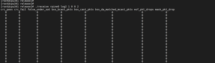
Example 1: If user_mask value = 2 , below output is expected:
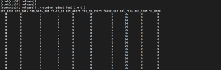
Example 2: If user_mask value = 9 , below output is expected:
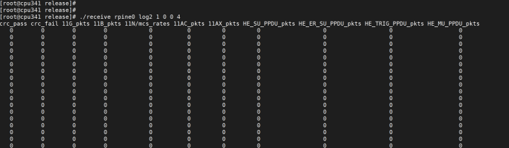
Example 3: If user_mask value = 4 , below output is expected:
If no user_mask value is given default stats are displayed as in below image:
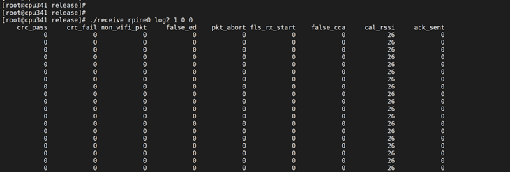
Once the above command is given on command line, periodically(For each sec) the stats will be displayed on the terminal.
Receive E2E Stats#
See the Compilation Steps and Installing the Driver sections for Wi-Fi E2E Connection.
Navigate to the release folder and run receive utility for E2E receive stats.
# cd release
# ./receive rpine0 <filename> <ch_num> <start/stop> <ch_width>Note : Make sure to disable power save while running E2E Receive stats