Getting Started with WiSeConnect™ SDK v3.x and EFR32™ Host in NCP Mode#
This guide describes how to get started with developing an application for the SiWx91x™ chipset family using the WiSeConnect™ SDK v3.x with an EFR32™ host in Network Co-Processor (NCP) mode, where the application runs on the EFR32 host and the connectivity stack runs on the SiWx91x chipset.
Note: The output images in this guide are for illustration purposes only. Details such as board names and version numbers may not exactly match the product.
Check Prerequisites#
Note: The software and hardware requirements mentioned in this section are specific to the example(s) recommended with this guide in the Create a Project section. If you are working with a different example, refer to its README page for the software and hardware requirements. To see the README page of a specific example, click on the Go to README link next to it in the Examples page.
Software#
Simplicity Studio
Simplicity software development kit (SiSDK (formerly GSDK)) with WiSeConnect 3 extension
Note:
We recommend using the latest SiSDK (formerly GSDK) version.
Hardware#
Wi-Fi Access Point (802.11 ax/b/g/n)
BRD4002A - Si-MB4002A Wireless Pro Kit Mainboard (hereafter referred to as WPK board).
One of the following NCP radio boards (hereafter referred to as EFR32 radio boards)
BRD4346A - SiWx917 Wi-Fi 6 and Bluetooth LE 4MB Flash Co-Processor Radio Board (hereafter referred to as SiWx917 radio board).
BRD8045A - EXP Adapter Board for SiWx917 Co-Processors (hereafter referred to as adapter board).
Windows/Linux/MacOS computer with a USB port
Type C USB cable compatible with the computer's USB port (for e.g., type C to type A if the computer has a type A USB port).
Note: The SiWx917 Wi-Fi 6 and Bluetooth LE Co-Processor EXP Expansion Kit (SiWx917-EB4346A) comes with the SiWx917 radio board and adapter board mentioned above.
Setup Software#
You may setup the following software in this section while waiting to receive the hardware:
Install Simplicity Studio#
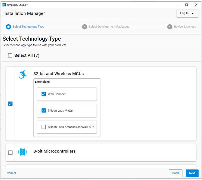
Download the latest version of Simplicity Studio and follow the installation instructions. During the installation:
select Install by technology type in the Installation Manager window, and
select the WiSeConnect extension under 32-bit and Wireless MCUs.
Install the GNU ARM v12.2.1 Toolchain#
Note: From v4.4.0 on, Simplicity SDK (formerly Gecko SDK) requires v12.2.1 of the GNU ARM toolchain to compile a project successfully. Follow the instructions in this section to install this toolchain version and configure it for your new projects.
Log in to Simplicity Studio if not already done.
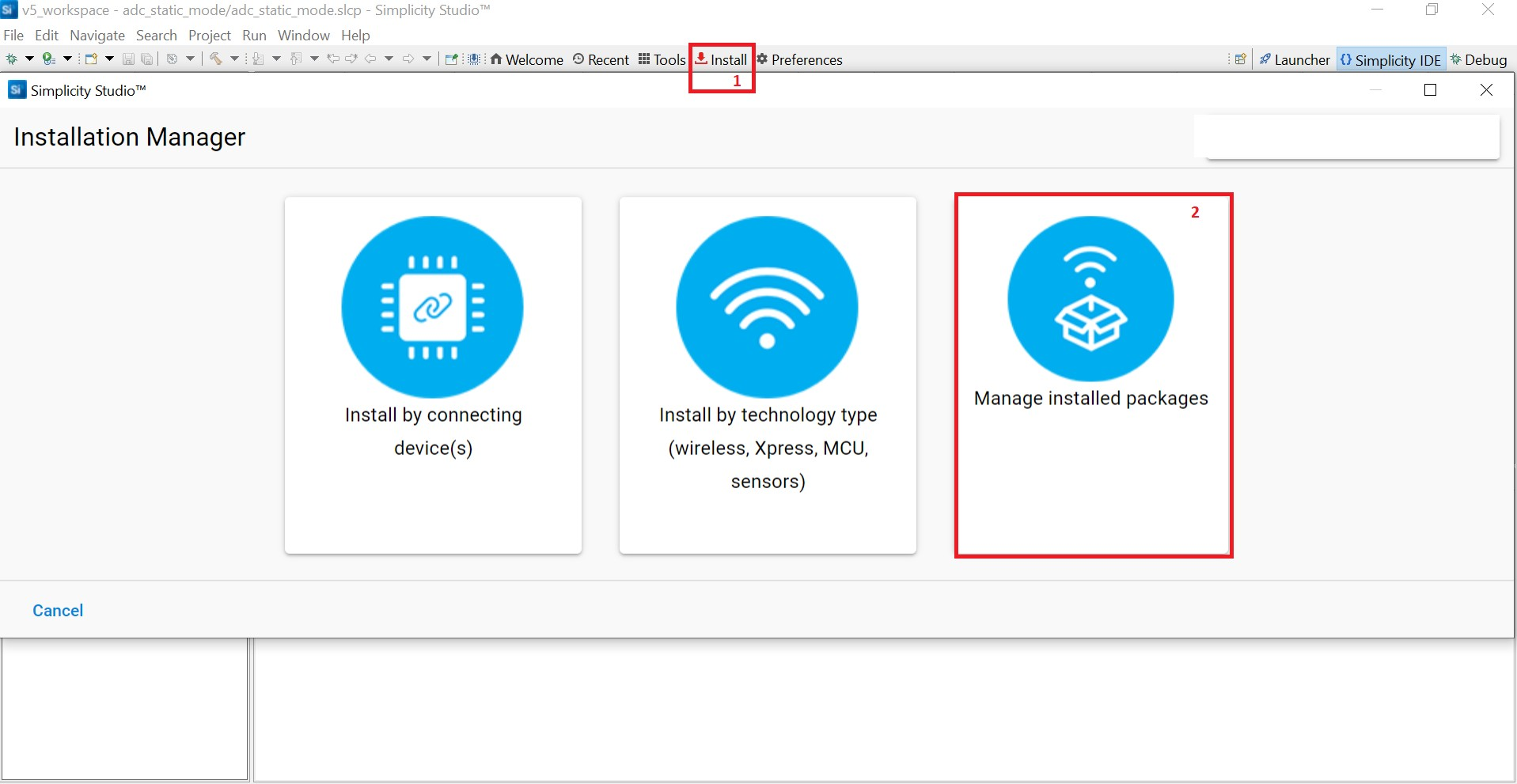
In the Simplicity Studio home page, select Install > Manage installed packages.
Select the Toolchains tab.
Click Install next to GNU ARM Toolchain (v12.2.rel1.xxxx.x) - 12.2.yyyy, where xxxx.x and yyyy may vary depending on the toolchain minor or patch version.
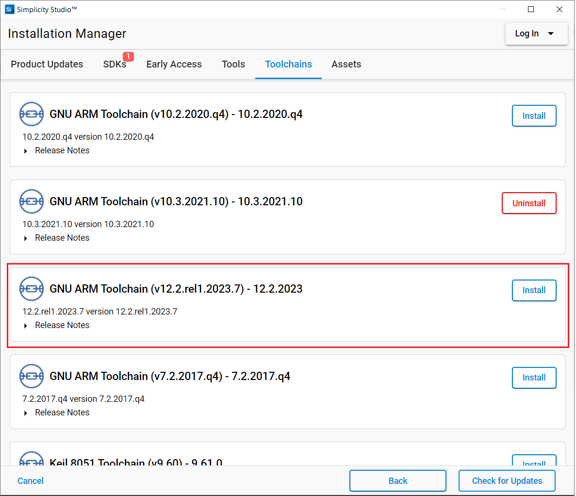
The toolchain will be installed.
Close the Installation Manager window.
In the Simplicity Studio home page, click Preferences.
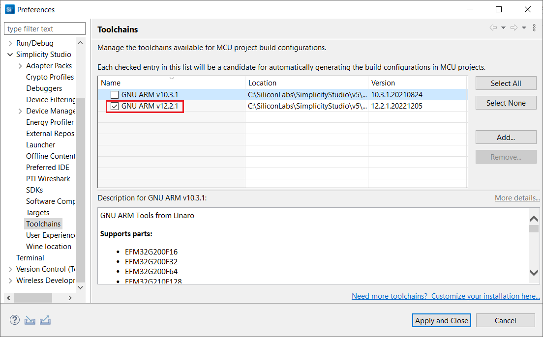
Expand the Simplicity Studio section in the Preferences dialog and select the Toolchains section.
Select GNU ARM v12.2.1 and un-select all other toolchains shown.
Click Apply and Close.
Note: If you have an existing project, see Silicon Labs community page for instructions to configure the toolchain version in your project.
Install the WiSeConnect 3 Extension#
If you already selected the WiSeConnect extension in the Install Simplicity Studio section, you may skip this section.
Before installing the WiSeConnect 3 extension, upgrade to a compatible SiSDK (formerly GSDK) version if not already done. See the Prerequisites section for the supported SiSDK (formerly GSDK) versions.
You may install WiSeConnect 3 through one of the following alternative paths:
Installation Manager (recommended)
Manage SDKs Window (hardware required)
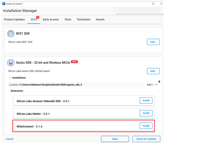
Install WiSeConnect 3 through the Installation Manager#
Log in to Simplicity Studio if not already done.
In the Simplicity Studio home page, select Install > Manage installed packages.
Select the SDKs tab.
Next to the WiSeConnect - 3.x.x extension, click Install.
Install WiSeConnect 3 through the Manage SDKs Window#
Note: You must have the hardware available before using these steps to install the WiSeConnect 3 extension.
Download the WiSeConnect v3.x source code from the following URL after substituting 3.x.x with the desired release version:
https://github.com/SiliconLabs/wiseconnect/archive/refs/tags/v3.x.x.zipIf you don't know your release version, go to the github releases page and select the version to download.
Unzip the downloaded
wiseconnect-3.x.x.zipfile. It will be extracted into a folder structure similar to the following:wiseconnect-3.x.x |--- wiseconnect-3.x.x |------ <source code>Launch Simplicity Studio and log in.
Connect the EFR32 and SiWx917 boards to your computer
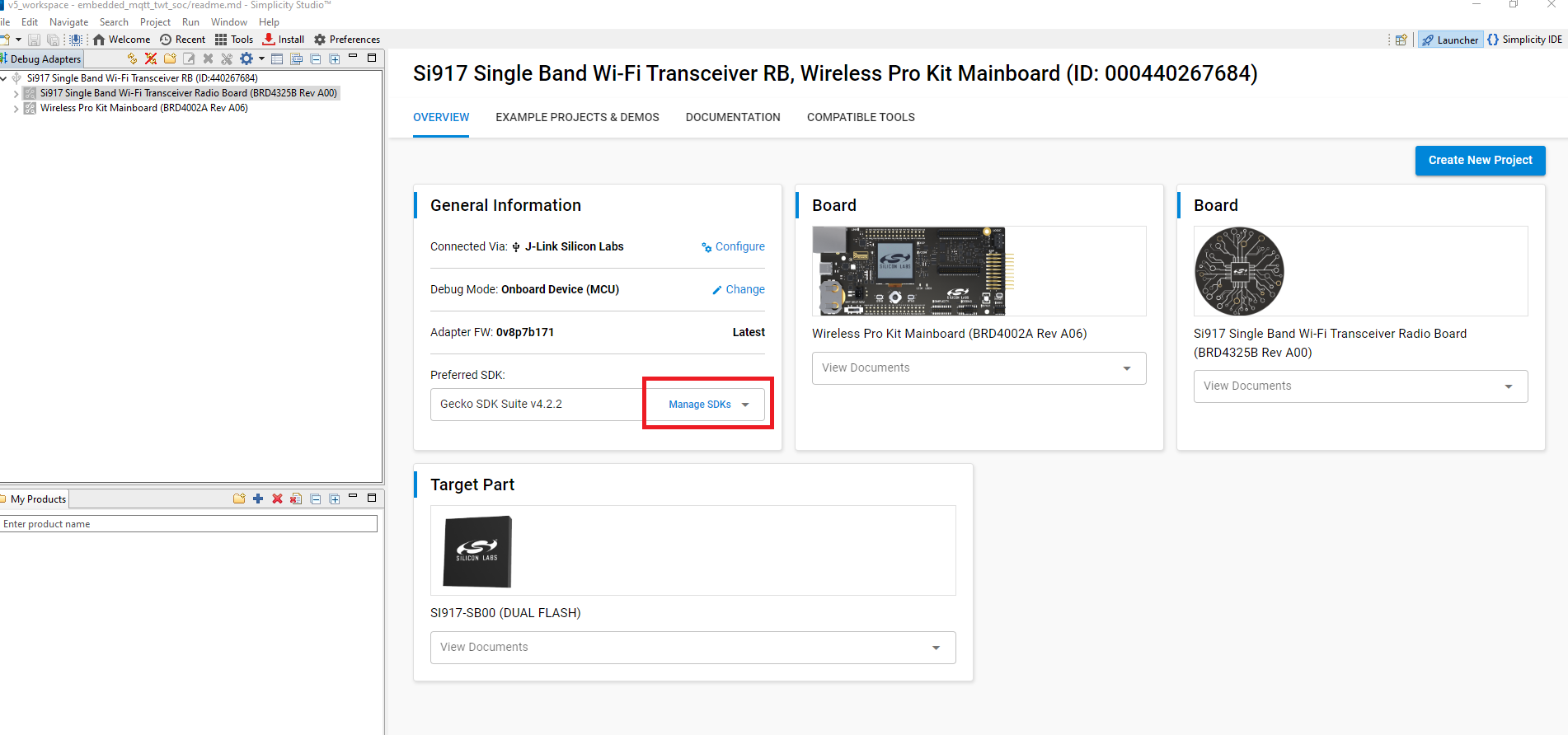
In the Debug Adapters pane, select your radio board.
In the General Information section, click Manage SDKs.
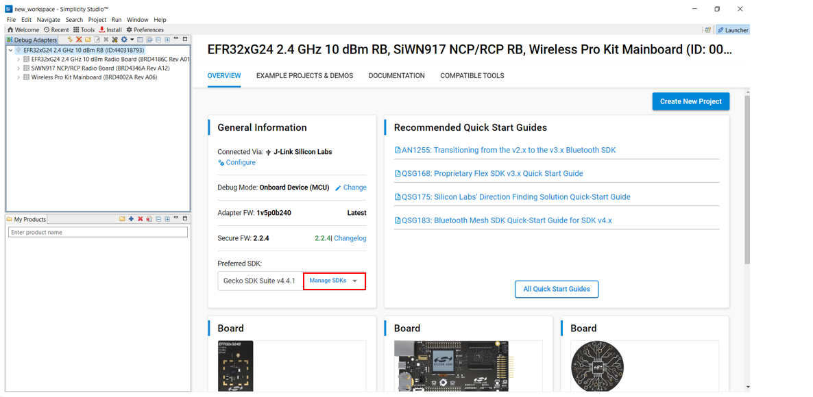
The Preferences window will be opened in the SDKs section.
Select Simplicity SDK (formerly Gecko SDK) Suite vx.x.x and click Add Extension.
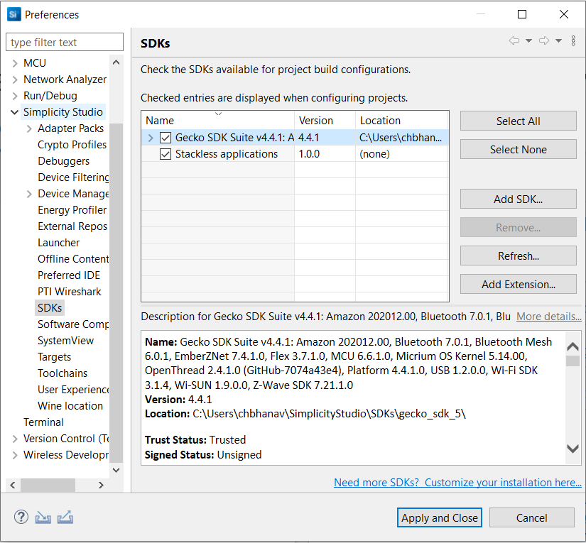
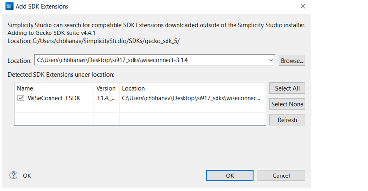
In the Add SDK Extensions window, click Browse.
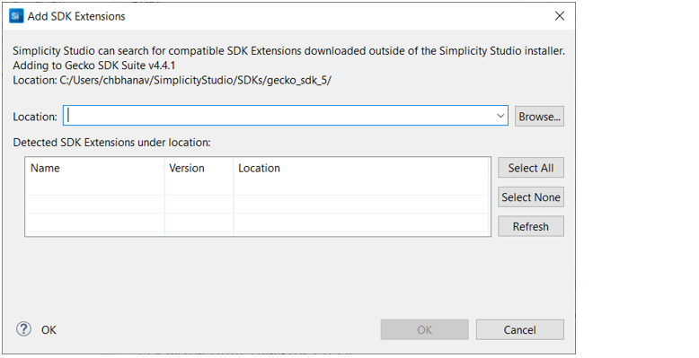
Locate and select the
wiseconnect-3.x.xsub-folder extracted in step 2 above which contains the source code.Studio will detect the WiSeConnect 3 SDK extension.
Select the detected extension and click OK.
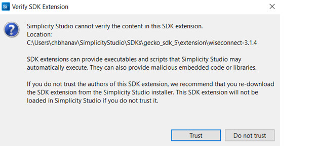
If a Verify SDK Extension popup is displayed, click Trust.
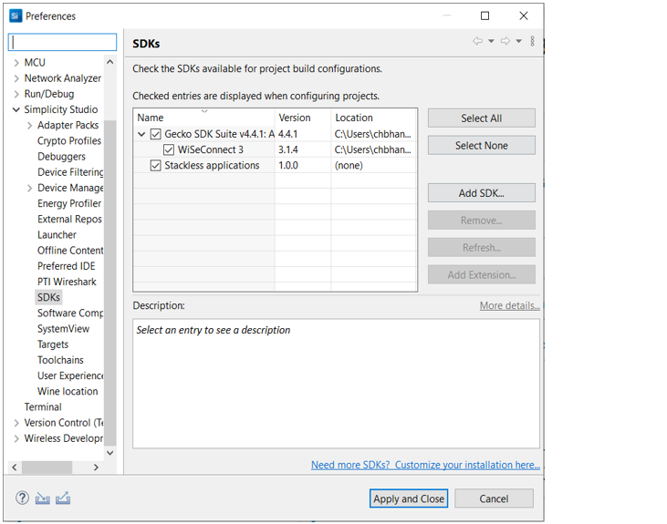
The selected WiSeConnect 3 extension will be displayed.
Click Apply and Close.
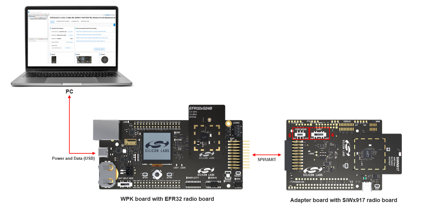
Connect the Boards to a Computer#
Plug the EFR32 radio board into the radio board connectors of the WPK board as shown below.
Plug the SiWx917 radio board into the radio board connectors of the adapter board as shown below.
Connect the adapter board to the EXP header on the EFR32 WPK board.
Make sure the UART switch on the adapter board is in the right position depending on the type of interface between the SiWx91x device and the external MCU host:
In case of a serial peripheral interface (SPI), the switch must be in the USB position.
In case of a universal asynchronous receiver-transmitter (UART) interface, the switch must be in the HOST position.
Make sure the PWR MODE switch on the adapter board is in the BUF position.
Connect the EFR32 WPK board to your computer using a type C USB cable.
Simplicity Studio will detect and display your EFR32 radio board.
Connect Hardware Flow Control Pins for NCP-UART with Hardware Flow Control#
Connect the CTS and RTS Pins from adapter board to the EFR32 WPK board as shown below.
BRD8045A Adapter board | EFR32 WPK board GPIO Breakout Pad |
|---|---|
B0105 | F8/EXP3 |
pin #35 on J101 | F9/EXP5 |
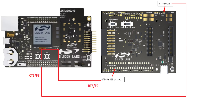
Note: SL_SI91X_UART_HIGH_SPEED_ENABLE and SL_SI91X_UART_HFC_ENABLE macros must be declared in the project to enable hardware flow control in NCP-UART.
Troubleshoot Board Detection Failure#
If Simplicity Studio does not detect your EFR32 radio board, try the following:
In the Debug Adapters pane, Click the Refresh button (having an icon of two looping arrows).
Reset both the WPK board and adapter board by pressing the RESET button and RST button on the corresponding boards.
Power-cycle the EFR32 radio board by disconnecting and reconnecting the USB cable.
Update SiWx91x Connectivity Firmware#
Note: The SiWx917 connectivity firmware version is tightly coupled with the WiSeConnect 3 extension version. You must update the SiWx917 connectivity firmware when:
you first receive an SiWx917 EXP expansion kit
you first receive an SiWx917 co-processor radio board, or
you upgrade or downgrade your WiSeConnect 3 extension
Disconnect the adapter board from the EFR32 WPK board, so that the host MCU connections do not interfere with the firmware update process.
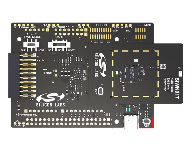
Plug the SiWx917 radio board into the radio board connectors of the adapter board as shown below.
Make sure the UART switch on the adapter board is in the USB position.
Make sure the PWR MODE switch on the adapter board is in the BUF position.
Connect the USB port of the adapter board to your computer's USB port using a type C USB cable.
Download Simplicity Commander and extract the downloaded archive. For example, the downloaded archive will be named SimplicityCommander-Windows.zip on Windows.
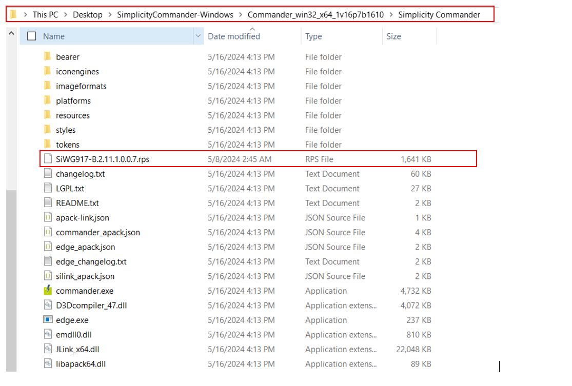
Extract the commander_xxx archive present in the root folder of the Simplicity Commander archive extracted in the previous step (for example, commander_win32_x64_1v16p8b1613.zip on Windows). In this example, 16 is the minor version, 8 is the patch version, and 1613 is the build number of the Simplicity Commander version downloaded.
Navigate to the Simplicity Commander sub-folder under the commander_xxx archive extracted in the previous step.
Copy the connectivity firmware from the
connectivity_firmware/standardsub-folder of the WiSeConnect 3 extension path to the Simplicity Commander sub-folder in the previous step.Note:
The
connectivity_firmware/litesub-folder can be ignored since the Lite OPN is not supported in NCP mode.The WiSeConnect 3 extension path is where the extension was downloaded during installation. If you're not sure what the path is, refer to the location in the Preferences > SDKs page shown on clicking Manage SDKs.
Press the RST button on the adapter board.
Click on the address bar at the top of the File Explorer window opened to the Simplicity Commander folder in step 8 above and highlight the current path.
Replace the highlighted path with the text
cmdand press Enter.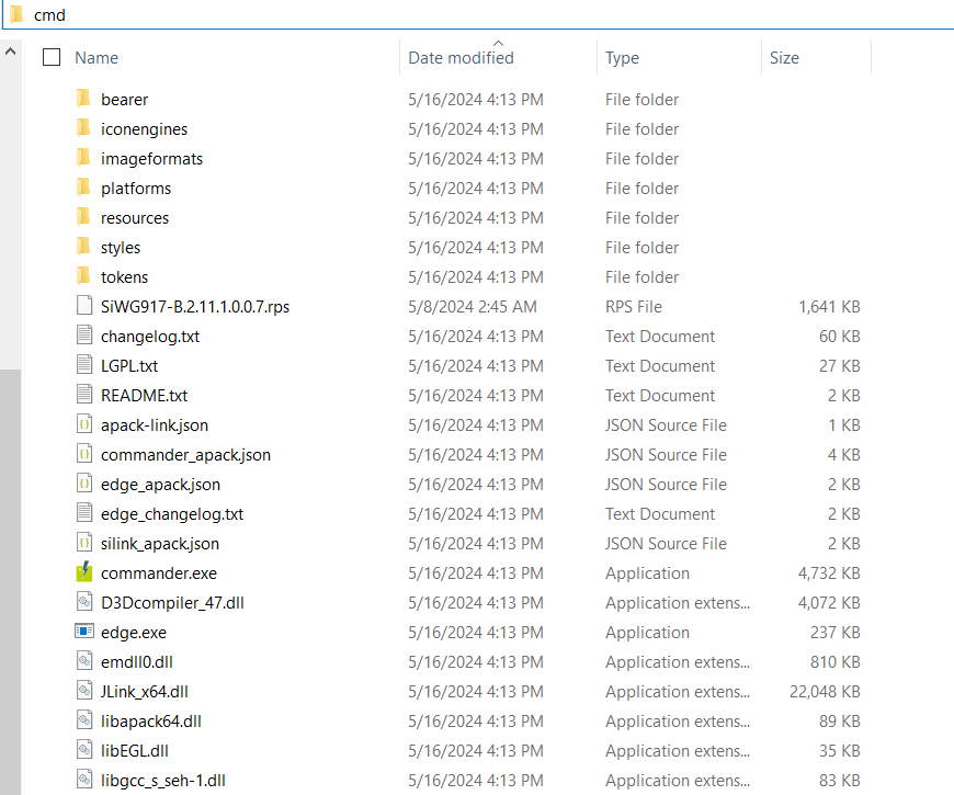
The Windows command prompt window will be displayed with the folder location set to the Simplicity Commander folder in step 8 above.
Find the name of the COM port for the connected adapter board.
Note: There are two ways to find the COM port of the connected adapter board on Windows.
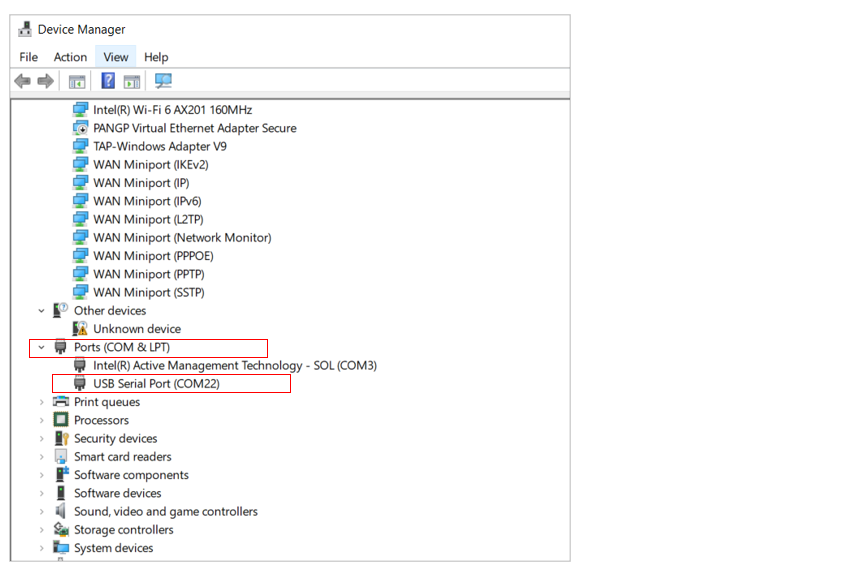
Through the Windows Device Manager:
Click Start and enter
Device Managerin the Type here to search field.Device Manager will be shown in the Start menu.
Open Device Manager.
Expand Ports (COM & LPT) in the list.
Examine the various COM ports shown to determine which one belongs to the connected adapter board.
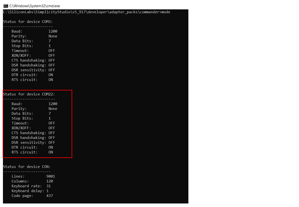
Through the Window command prompt:
Enter the command
mode.Examine the various COM ports shown to determine which one belongs to the connected adapter board.
On the Windows command prompt opened in step 13 above, enter the following command to update firmware:
commander serial load <firmware file name> --showprogress --serialport <COM PORT> -d si917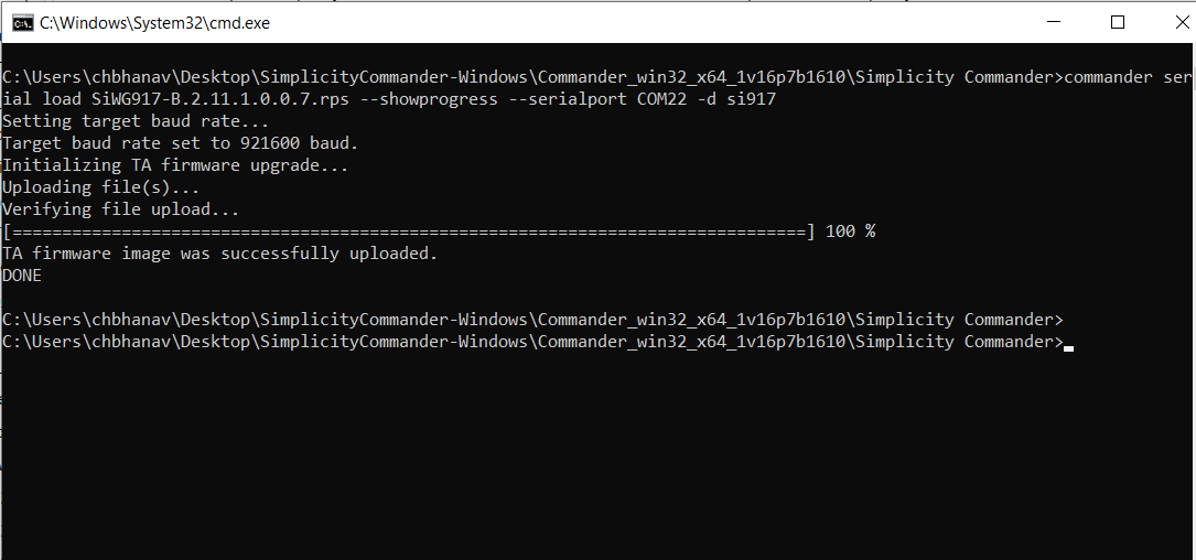
Note:
In the command above, <firmware file name> is the name of the connectivity firmware file copied in step 13 above.
The above command sets the baud rate to 921600 and performs an SiWx917 NCP firmware update serially over the connected adapter board. It takes less than 2 minutes to perform a firmware update.
Create a Project#
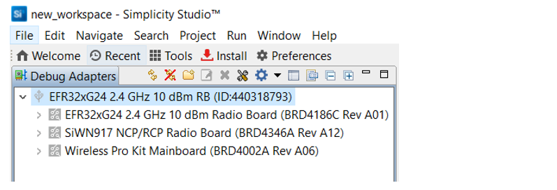
Log in to Simplicity Studio and connect the EFR32 and SiWx917 boards to your computer.
Go to the Debug Adapters section.
Select the detected EFR32xG24 radio board from the displayed list.
Note: If you don't have the EFR32 radio board or you have not connected it to your computer, you may still view the example projects from the Launcher:
Select the Launcher from the toolbar.
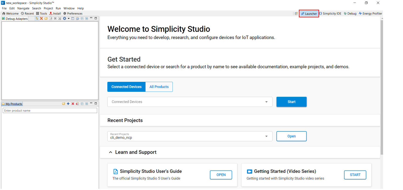
In the My Products section, search for EFR32xG24.
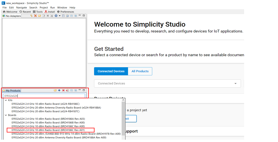
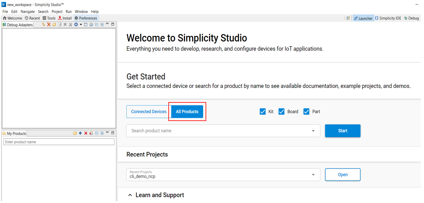
Alternatively, you may select All Products on the Launcher page and search for EFR32xG24.
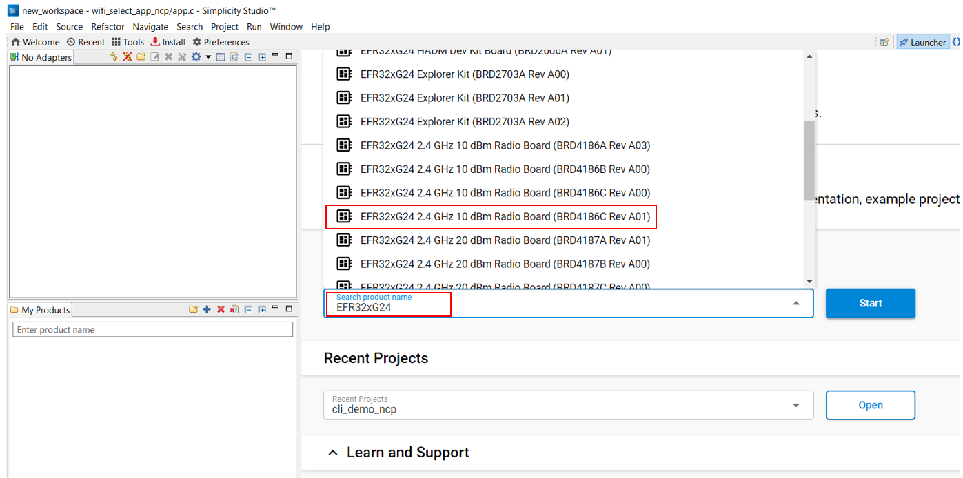
The Launcher page will display the selected radio board's details.
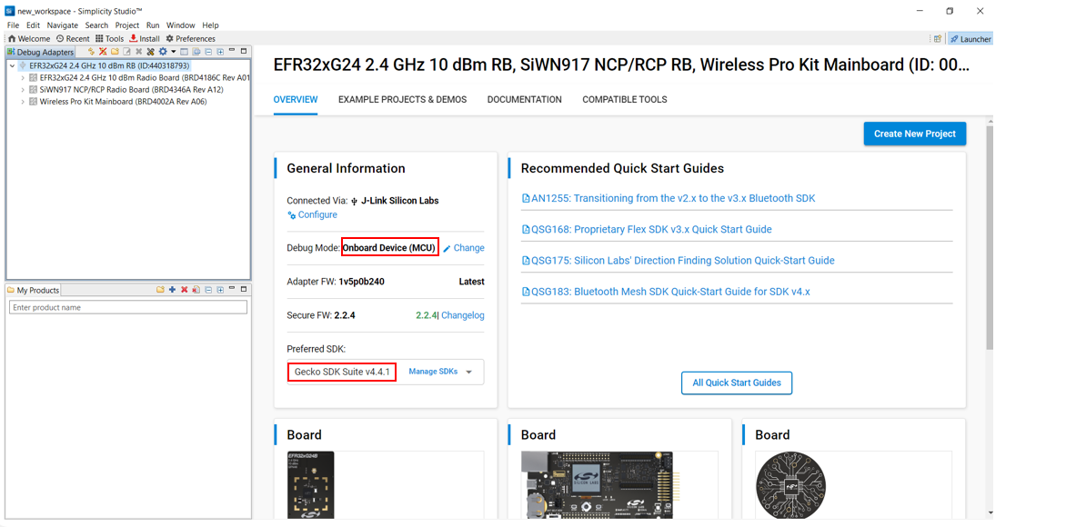
Select the OVERVIEW tab.
Verify the following in the General Information section:
The Debug Mode is Onboard Device (MCU).
The Preferred SDK is the version you selected earlier.
Select the EXAMPLE PROJECTS AND DEMOS tab.
Locate the example you want and click CREATE.
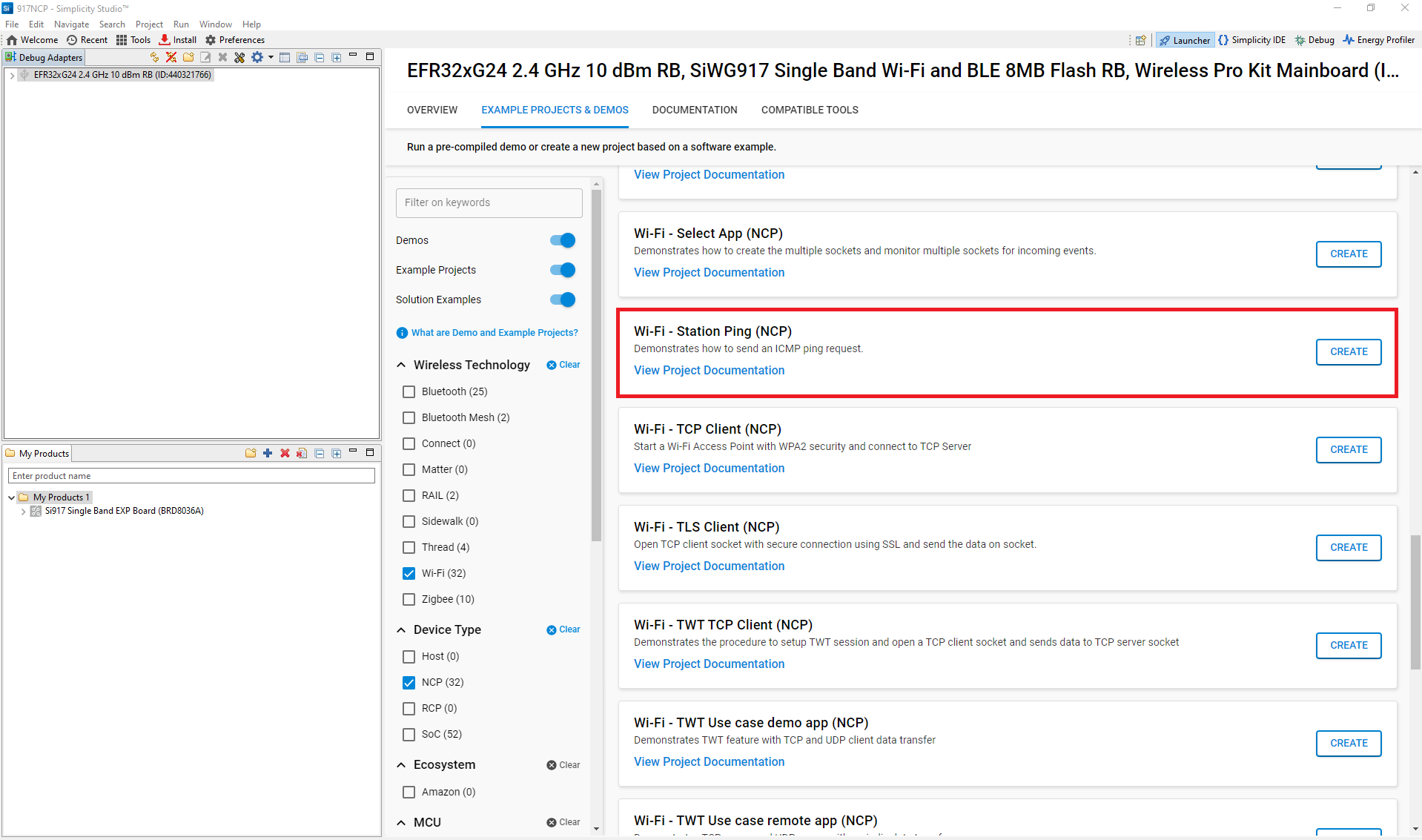
Note:
The following example is recommended for your first project, depending on the type of host connection:
Wi-Fi - Station Ping (NCP) - For connection over SPI
Wi-Fi - Station Ping (UART NCP) - For connection over UART
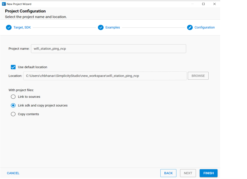
In the New Project Wizard window, click FINISH.
Configure an Application#
Configure the settings for your example, as described in the Application Build Environment section in the README page of your example.
Note:
You may use the Component Editor to configure the components in your example.
You may use the Pintool to configure the pin mappings in your project for your SiWx917 system-on-chip.
Build an Application#
Note: If you upgraded from a SiSDK (formerly GSDK) version earlier than v4.4.0, upgrade your GNU ARM Toolchain. See the GNU ARM v12.2.1 Toolchain section.
Launch Simplicity Studio and log in.
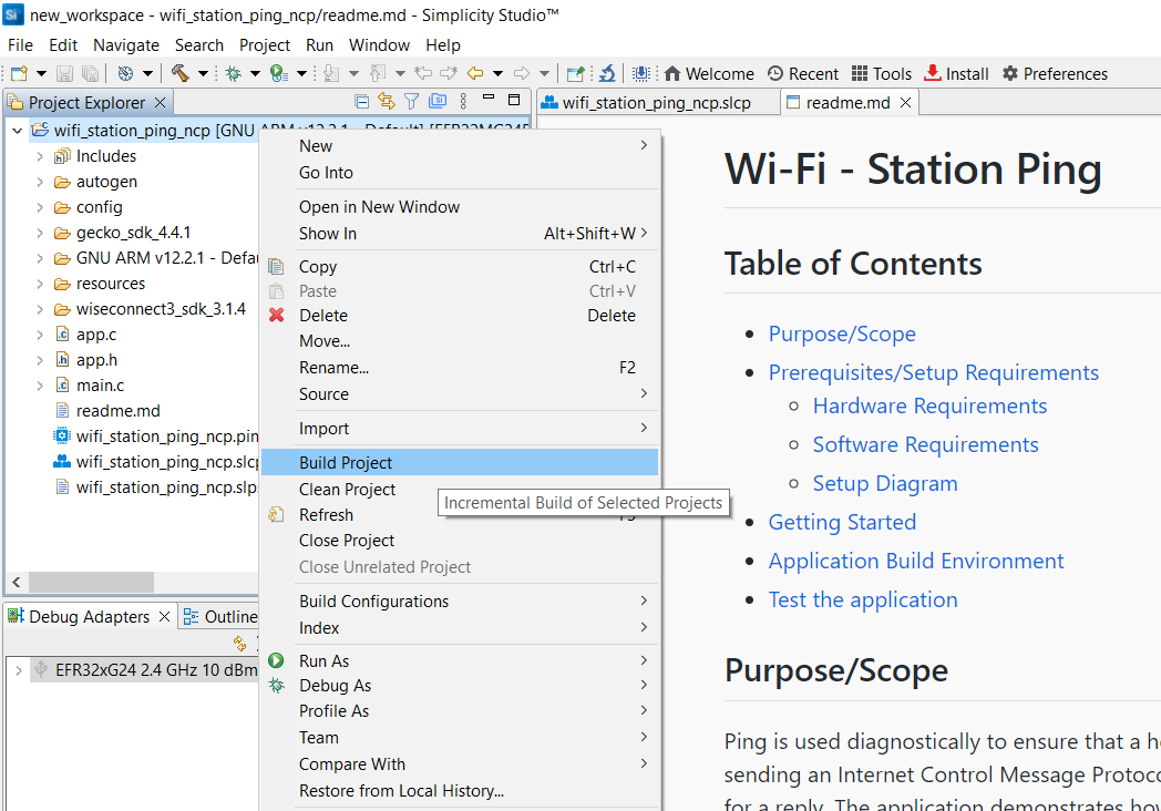
In the Project Explorer pane, right-click the project name and select Build Project.
You may also click the Build button with a hammer icon on the Simplicity IDE perspective toolbar.
Console Input and Output#
The method for exchanging data with the EFR32 host depends on the type of interface between the EFR32 host and the SiWx91x device.
Console Input and Output with a SPI Interface#
Connect your EFR32 and SiWx91x boards to your computer.
Open Simplicity Studio.
In the Debug Adapters pane, right-click on your radio board and click Launch Console.
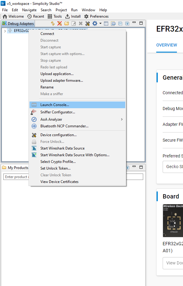
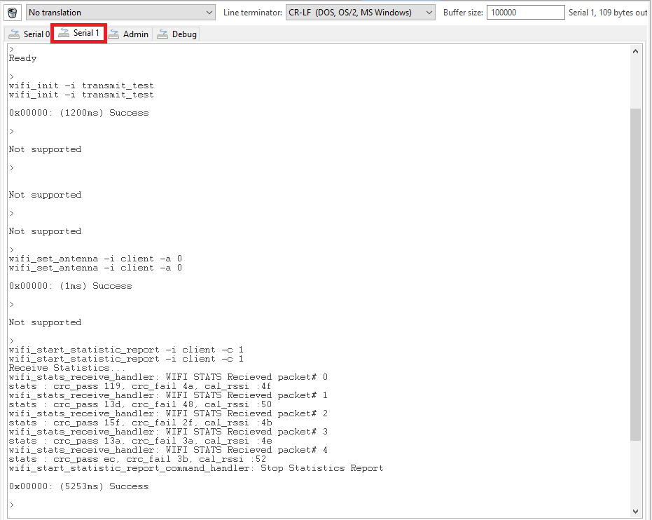
Select the Serial 1 tab.
Place the cursor inside the text input field and hit Enter.
This completes the console setup for SPI interface. After you flash and run the application, the console output will start getting displayed in the Serial 1 tab.
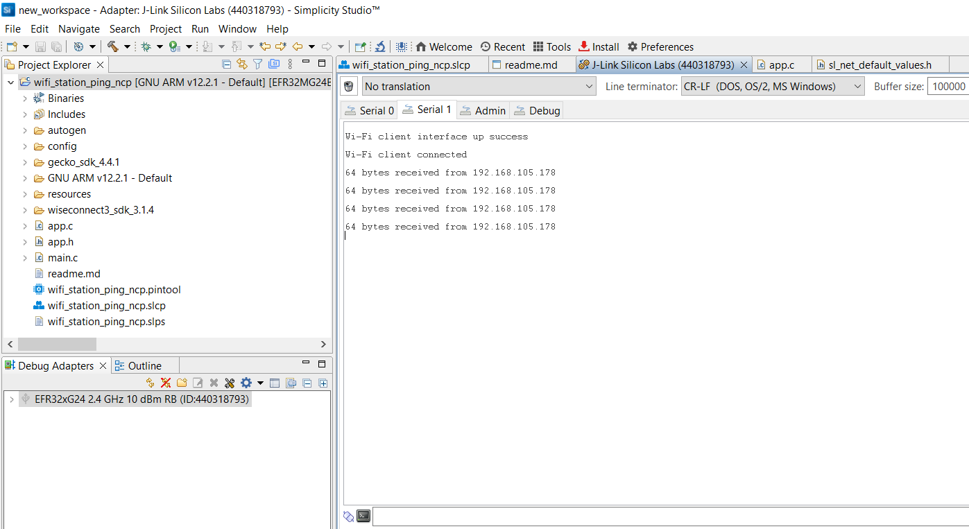
Console input can be entered and sent to the device.
Console Input and Output with a UART Interface#
Download and install J-Link Sofware from https://www.segger.com/products/debug-probes/j-link/tools/rtt-viewer/.
Connect your EFR32 and SiWx91x boards to your computer.
Before we start streaming the logs over RTT, make sure you have entered the desired execution mode.
Using Flash an Application:
If the application is executed in "Run As", RTT can connect to the device after the application is flashed onto the device.
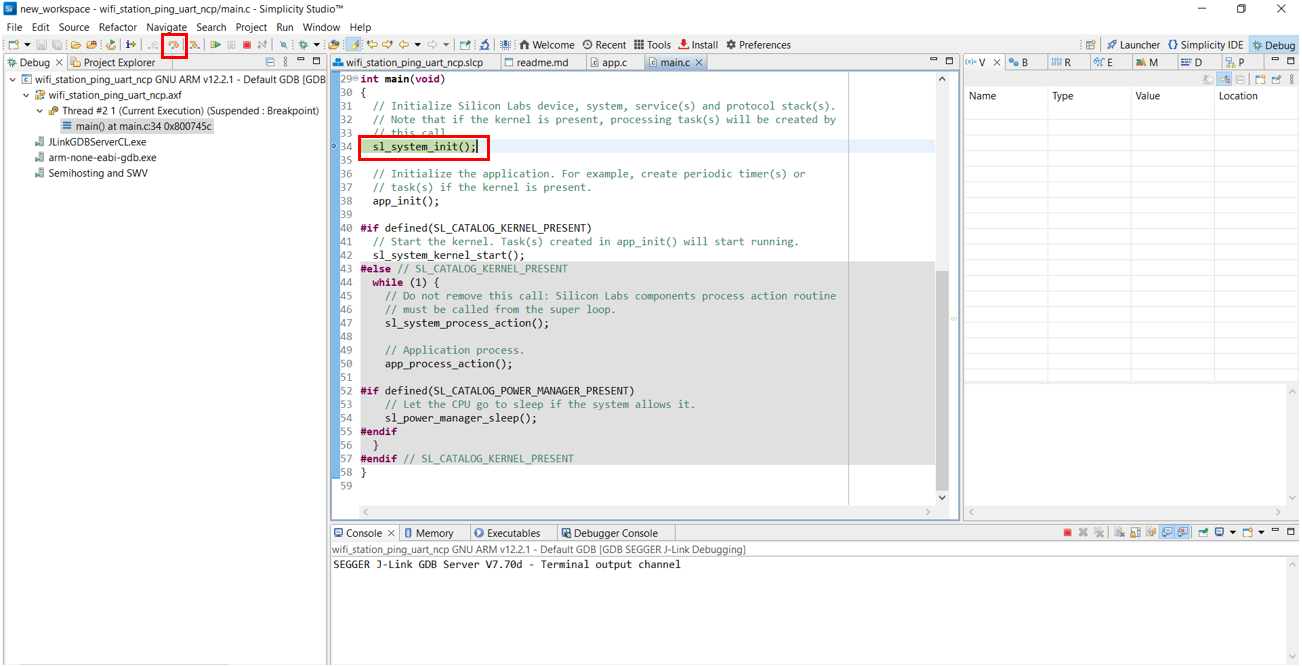
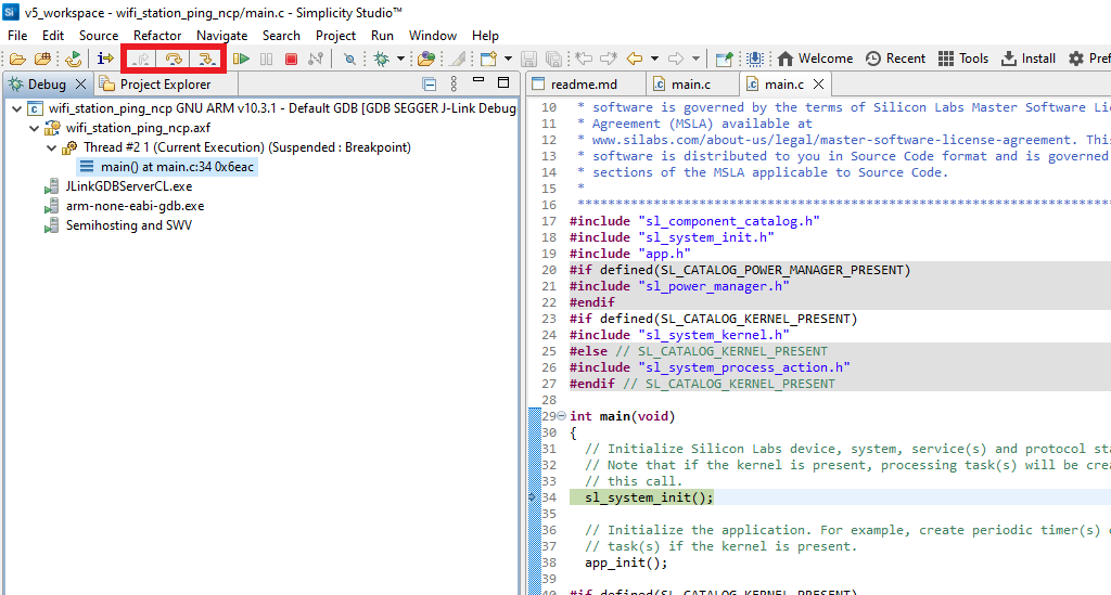
Using Debug an application:
If the application is executed in "Debug As", first we must enter the debug window and step over the
sl_system_init()function so that the RTT block is initialized for logging as shown below.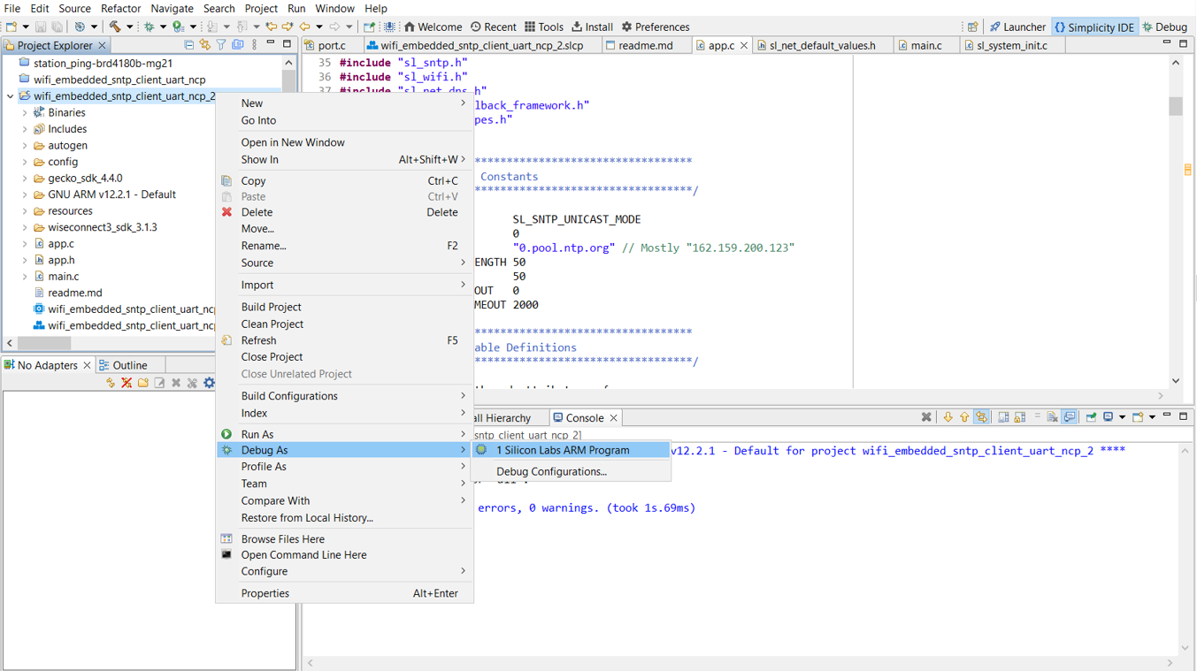
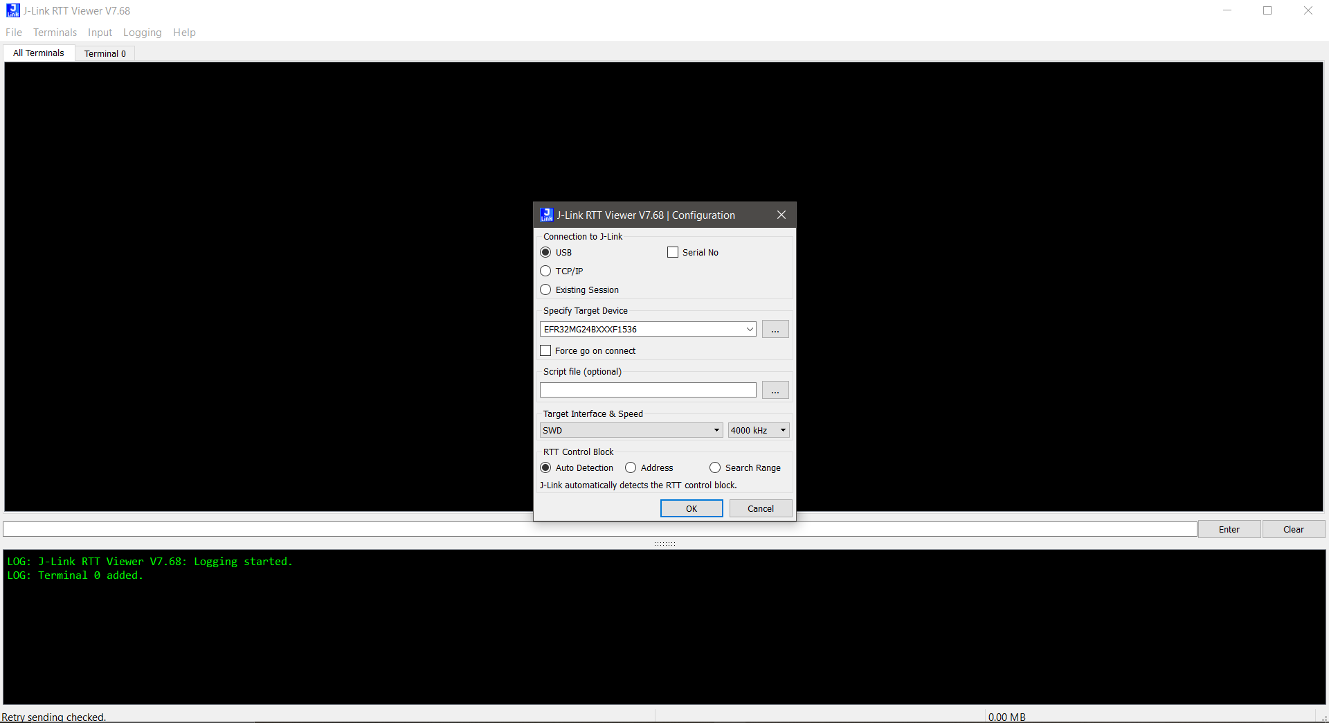
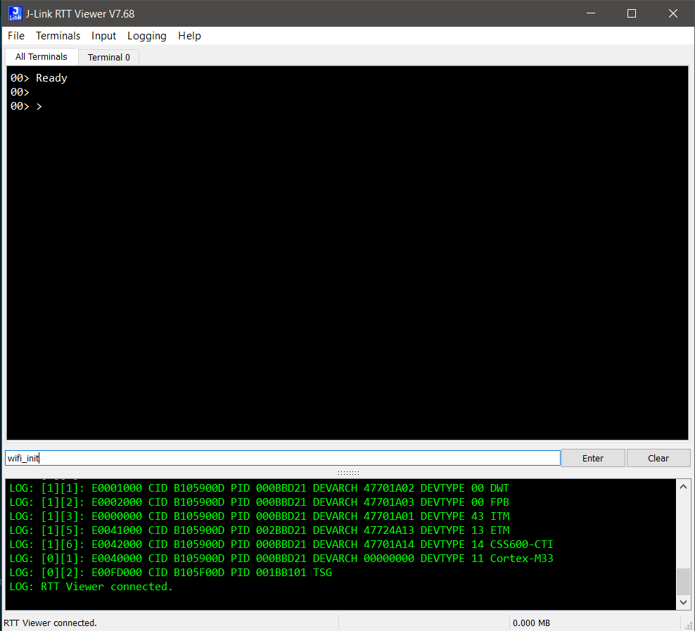
Open J-Link RTT viewer.
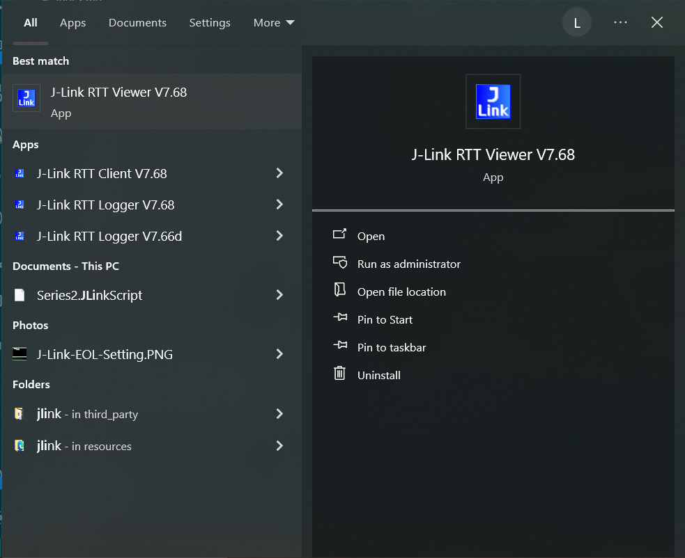
The device configuration dialog box is displayed.
Make sure the correct device is specified in the Specify Target Device field.
Enter the other fields as shown in the screen shot below.
Click OK.
Note: You must click File > Disconnect to close the RTT connection (if already connected) before initiating the debugging or flashing of an application.
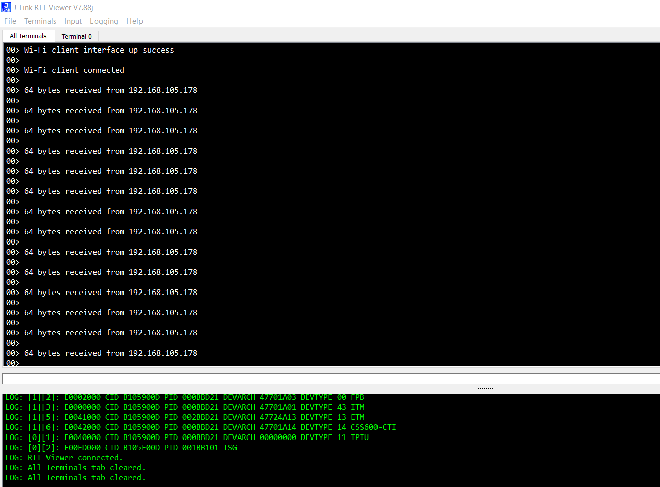
Logs will be displayed in the RTT terminal once connection is successfull.
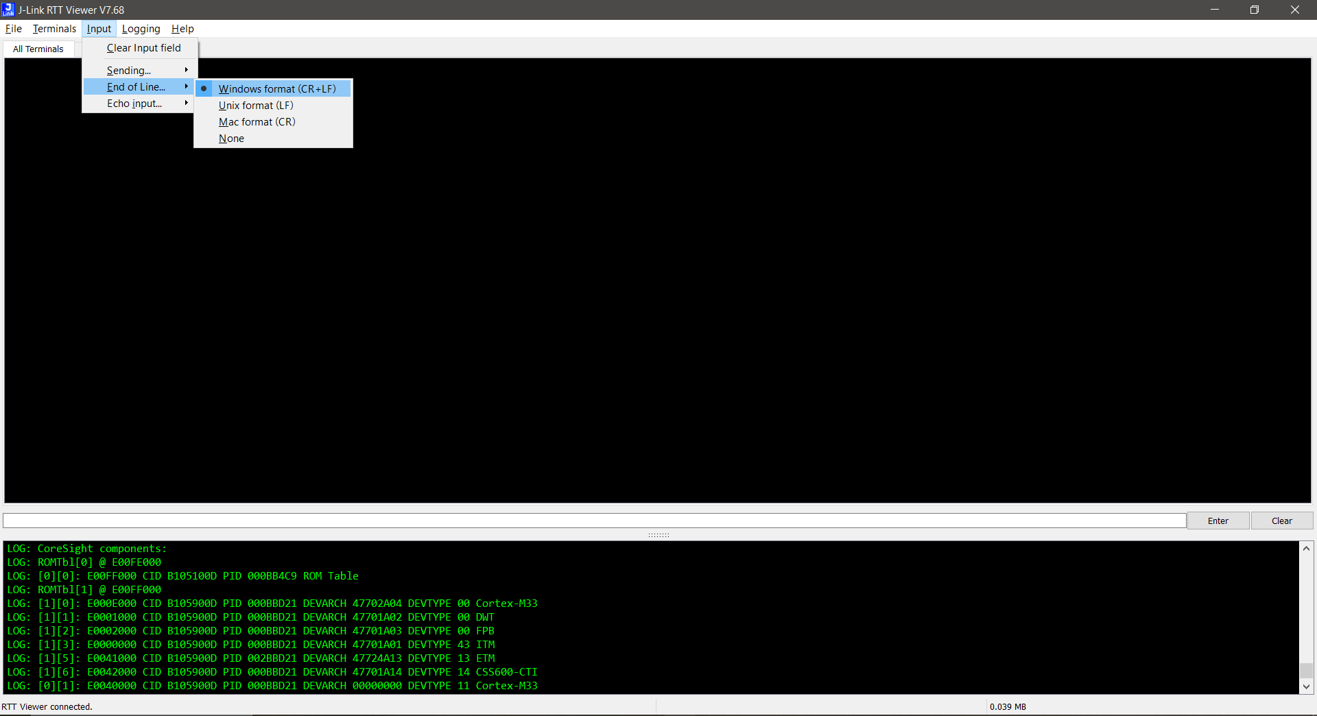
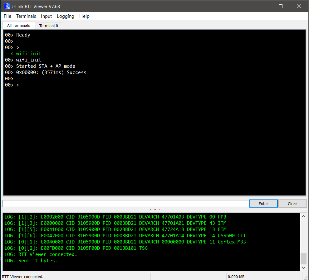
For the application which requires user input:
Select Input > End of Line... > Windows format (CR + LF) from the menu to set the end-of-line characters.
Select Input > Sending... > Send on Enter from the menu so that the entered input is sent to the EFR32 chipset when you click Enter.
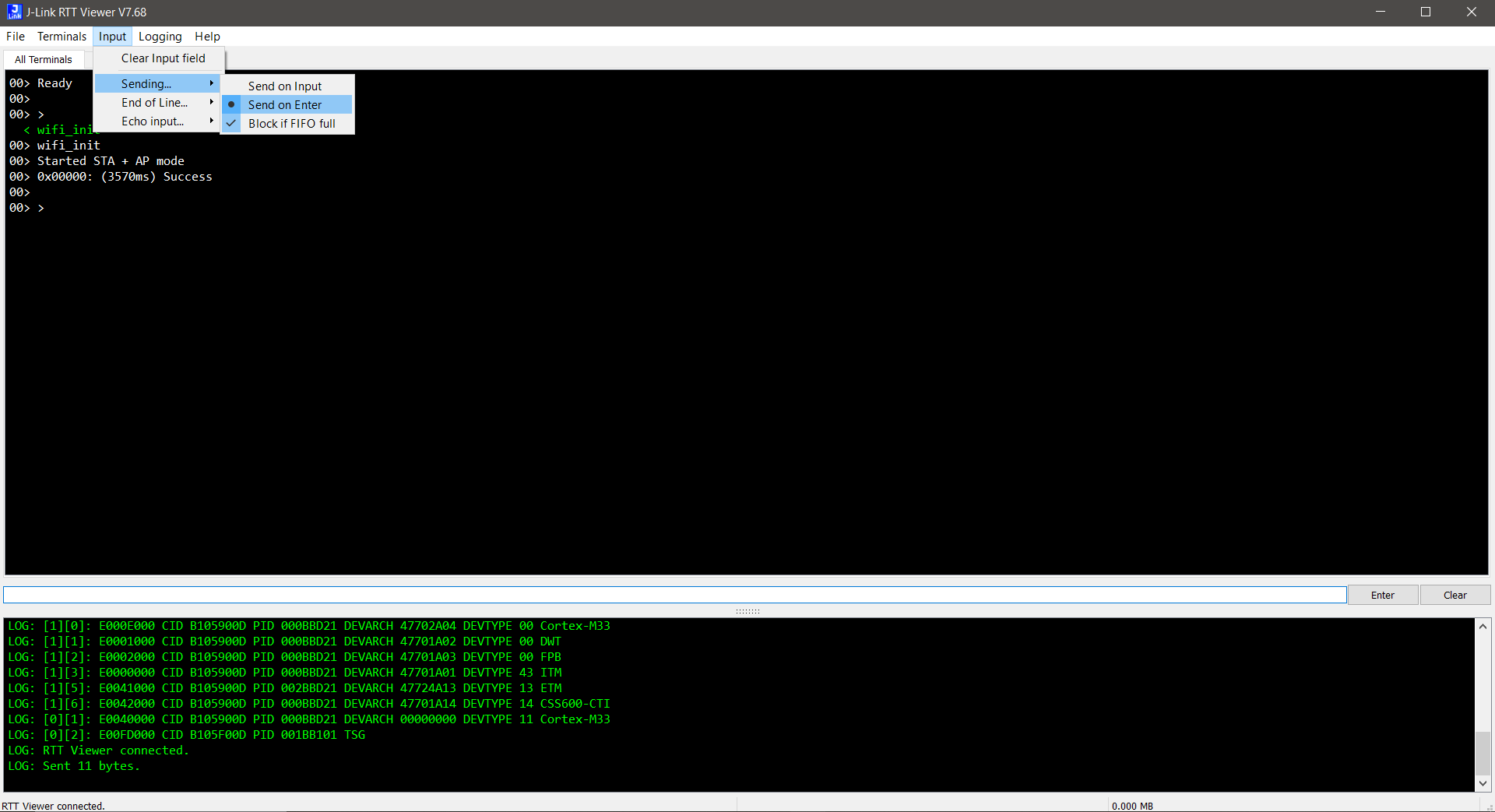
To send user input, enter data in the input box below the terminal output and click Enter.
Transmitted user input is shown on the RTT terminal in green.
Flash an Application#
Note: Make sure the bootloader image is flashed separately on to the EFR32 host MCU. Refer to the Simplicity SDK (formerly Gecko SDK) Bootloading Reference for more information.
There are two alternative methods to flash an application to the application processor of the SiWx91x device:
Flash an Application Built Using Simplicity Studio#
Build the application as described in the Build an Application section.
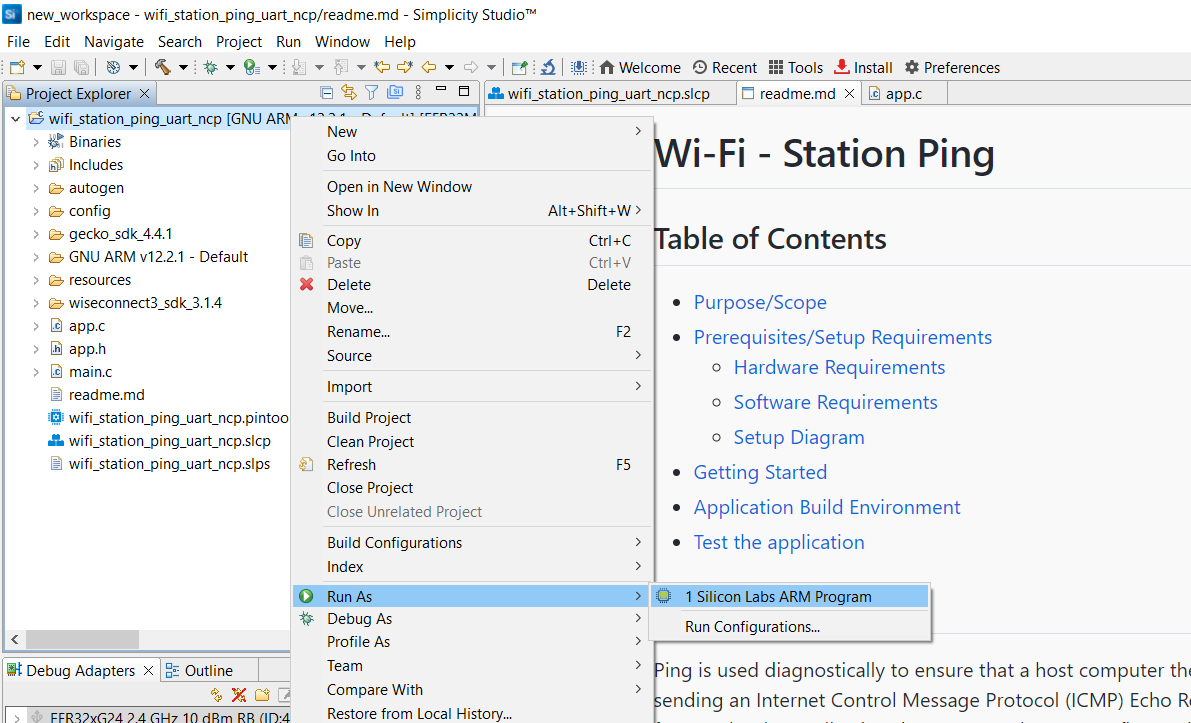
In the Project Explorer pane, right-click on your project name and select Run As > 1 Silicon Labs ARM Program.
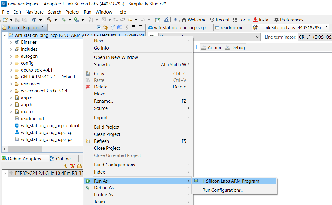
The application binary will be flashed on the EFR32 radio board and the application will start running.
View the standard output or enter input data as needed. See the Console Input and Output section.
Note: See the troubleshooting section in case the application fails to flash.
Flash the Application Binary#
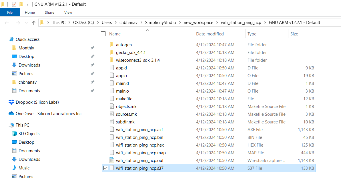
If the binary was built as described in the Build an Application section, a file with a
.s37extension is generated. This file will be available under GNU ARM vXX.x.x - Default in the users workspace. To see its location in your computer's file system, right-click on the.s37file and select Show In > System Explorer.Alternatively, you may have obtained a
.s37file through another means such as someone else building and providing the binary to you.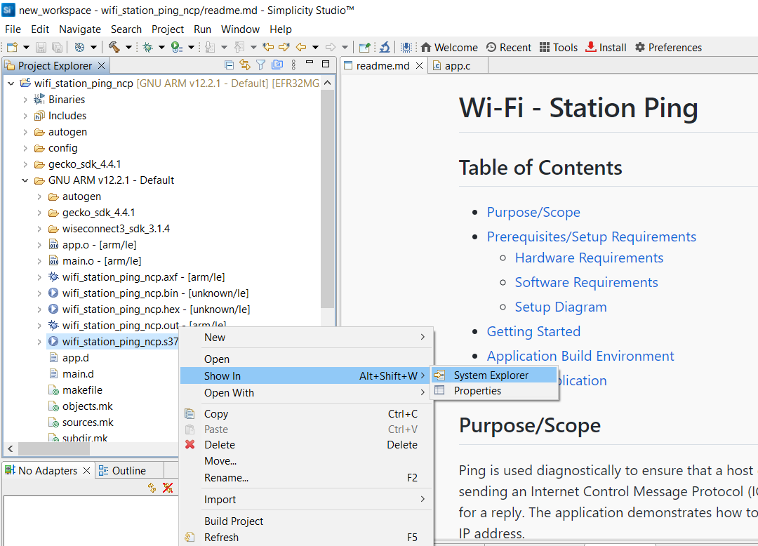
The instructions to flash the application binary are almost the same as those for flashing an SiWx91x firmware file, except for the point noted below:
Instead of choosing the SiWx91x firmware file, select the
.s37you obtained in step 1 above.
Note: If you don't see
.s37files in the sub-folder, select All files in the file filter field in the Browse dialog.
Troubleshoot an Application Flash Failure#
The application may fail to flash for one of the following reasons:
Error code 102 is displayed in the logs, indicating that ISP mode is enabled. Try the following steps:
Press and hold the ISP button on the radio board.
Press and release the RESET button on the WPK board.
Release the ISP button on the radio board.
Retry flashing the application.
"Could not connect debugger. Could not connect to target device" is displayed in the logs, indicating that the application processor is in a low power state with no flash access. Try the same steps as those described above for error 102.
Unknown reason - try re-launching Simplicity Studio.
Studio failed to detect your board. See the Troubleshoot Board Detection Failure section.
Run the Application#
Once you flash the example, you may refer to the Test the Application section of its README page to explore its output.
The other sections of the README like the Purpose/Scope section provide more information about the example.
See the Examples page to explore all available examples including their supported host interfaces (SPI and/or UART) and to view their README pages.
Debug an Application#
In the Project Explorer pane, right-click the project name and select Debug As > 1 Silicon Labs ARM Program.
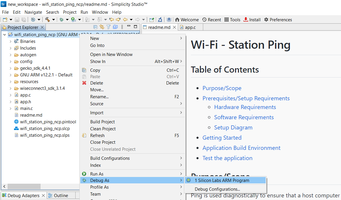
Studio will switch to debug mode and halt execution at the
main()function in your application.Add a break point in the desired location of the code and click the Resume button (having an icon with a rectangular bar and play button).
Execution will halt at the break point.
Use the following debug functions to direct the execution of the code:
Step In button (having an icon with a arrow pointing between two dots).
Step Over button (having an icon with an arrow going over a dot).
Step Out button (having an icon with an arrow pointing out from between two dots).
View the standard output or enter input data as needed. See the Console Input and Output section.
Troubleshoot an Application Debug Failure#
The application may fail to enter the debug mode due to one of the following reasons:
Studio failed to halt execution at the
main()function. Try the following steps:Click the Suspend button (having a pause button icon).
Click the Reset button (having an icon of a play button with an arrow underneath).
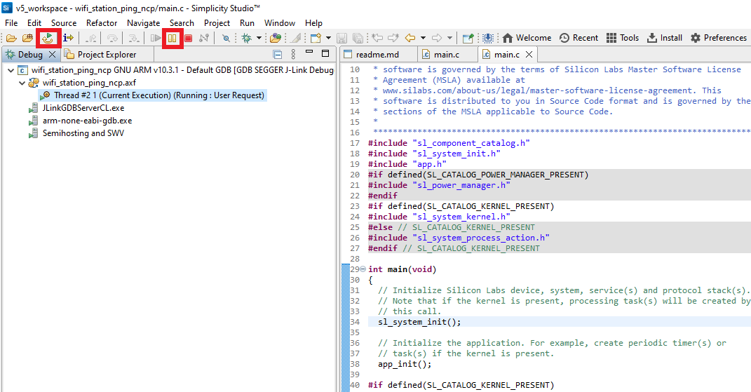
Retry debugging the application.
For additional tips, see the Troubleshoot an Application Flash Failure section. Follow the suggested steps and then, instead of retying the flashing of the application, retry debugging the application.
Customize Application Components#
Simplicity Studio allows you to add or remove functional components in your application, such as BSD Sockets.
Note: For information about the functional components available with WiSeConnect SDK v3.x, see the Application Components section.
Add a Component#
In the Project Explorer pane, double-click the project_name.slcp file.
Select the SOFTWARE COMPONENTS tab.
Select the SDK Extensions filter.
Browse or search for and select the component that you want to install.
Click Install.
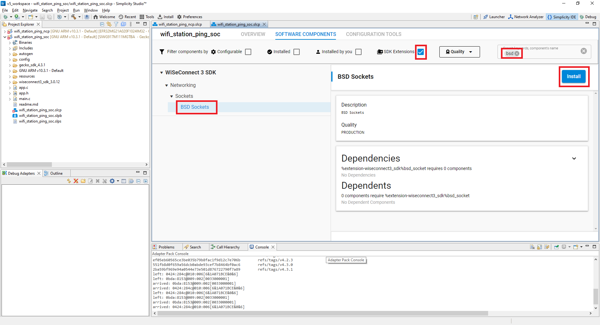
Note: The image is for illustration purposes only. Component and other details may not exactly match the product.
Studio will add the component and display a success message.
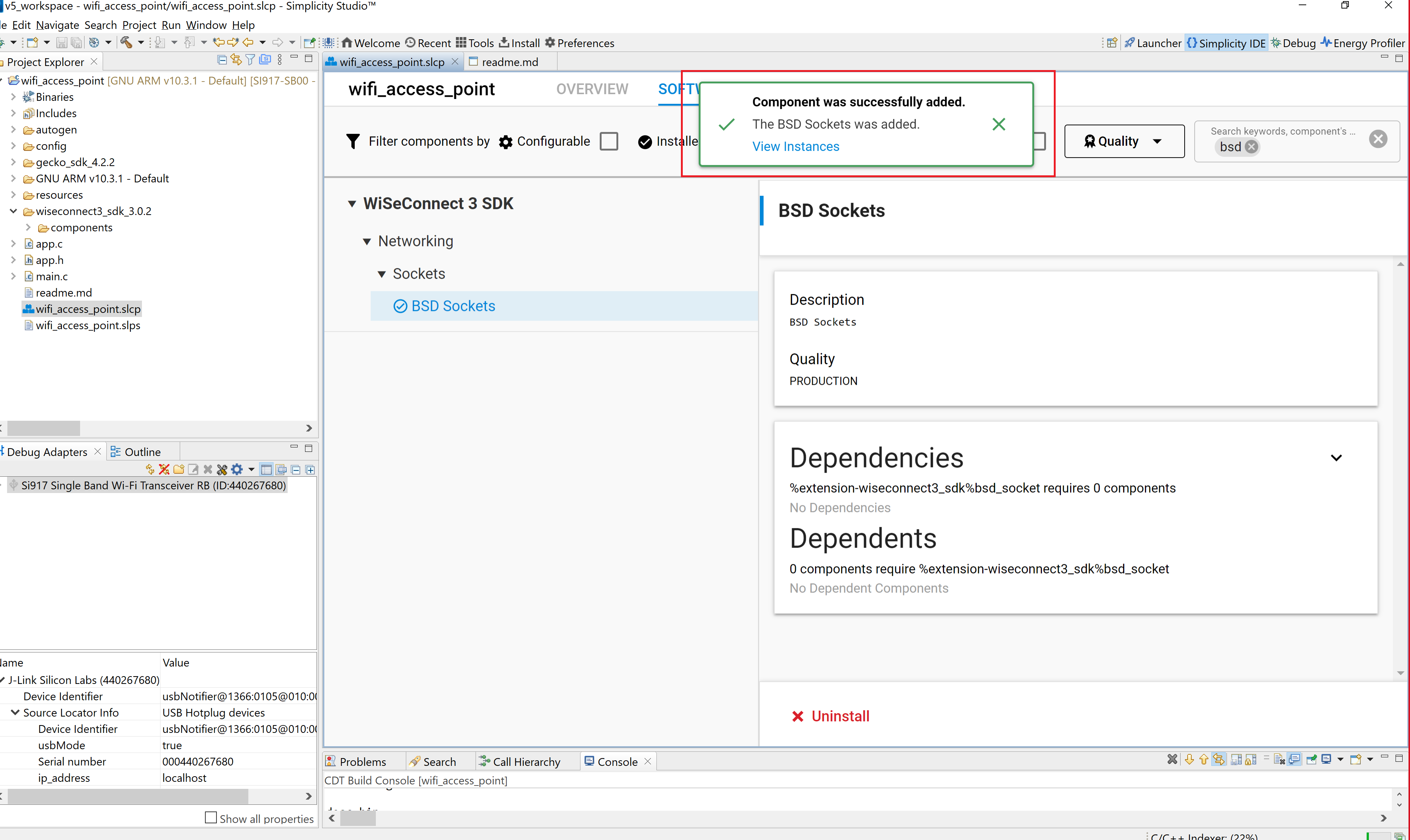
Note: The image is for illustration purposes only. Component and other details may not exactly match the product.
Note: You may use the Component Editor to configure a component after adding it or to configure other components in your example.
Remove a Component#
View the list of WiSeConnect 3 extension components by following steps 1-3 of the previous section.
Select the Installed filter to view the components you have installed.
Browse or search for and select the component you want to remove.
Select the component and click Uninstall.
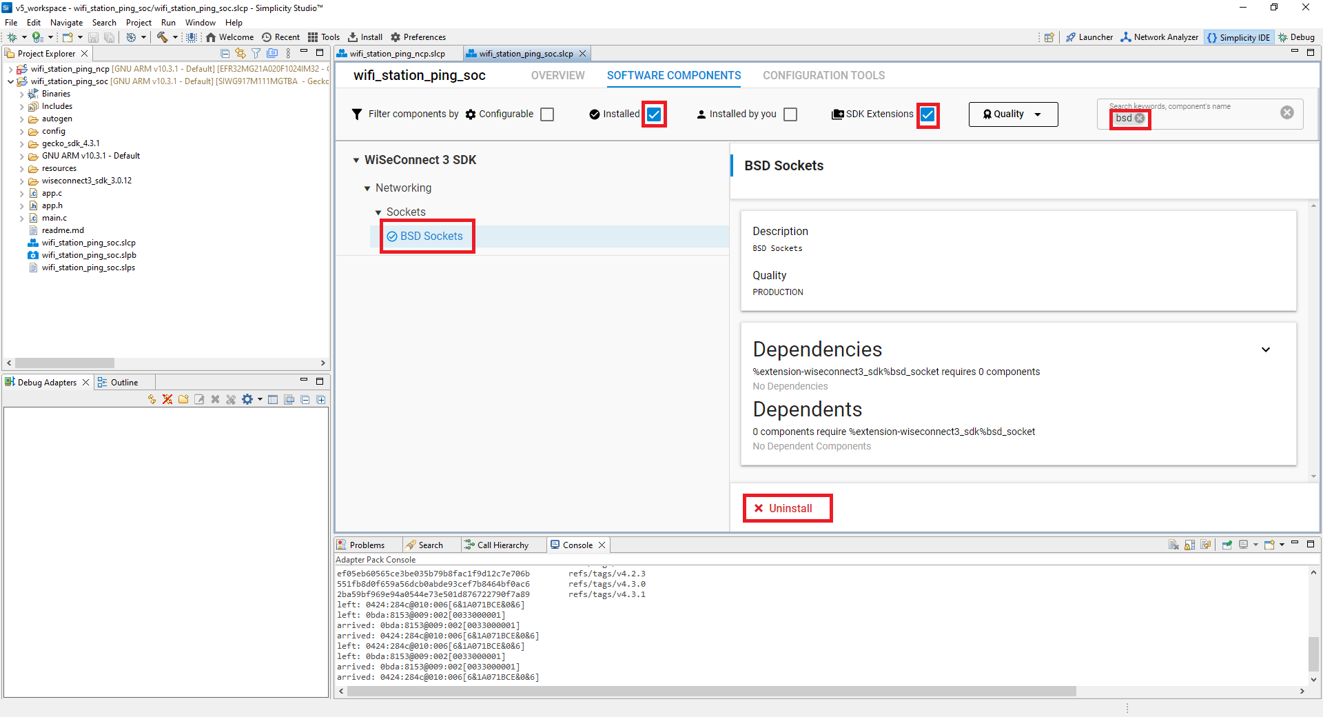
Note: The image is for illustration purposes only. Component and other details may not exactly match the product.