SiWx917 Current Consumption Analysis#
This section describes Reference examples and Setup used to measure current consumption during various stages such as during wireless scan, wireless connection, power save modes, etc.
Reference Examples#
The following are the reference examples in the WiSeConnect SDK for configuring Power Save Modes.
For Connected Power Save Modes configuration, refer to the Power Save Standby Associated example.
For Unconnected Power Save Modes configuration, refer to the Power Save Deep Sleep example.
For TWT Power Saving Mechanism, refer to the TWT TCP Client, TWT Use Case Demo App examples.
Prerequisites#
Hardware Used#
SiWx917 Wi-Fi 6 and Bluetooth LE Co-Processor EXP Expansion Kit
BRD8045A EXP Adapter Board for SiWx917 Co-Processors (hereafter referred to as Adapter Board)
BRD4346A SiWx917 Wi-Fi 6 and Bluetooth LE 4MB Flash Co-Processor Radio Board (here after referred to as SiWx917 NCP Radio Board)
xG24-PK6009A EFR32xG24 +10 dBm Pro Kit
BRD4002A Wireless Pro Kit (WPK) Mainboard
BRD4186C Radio Board
Keysight N6705C DC Power Analyzer - for measuring voltage across SiWx917 chip
Access Point (Used only in case of Connected Power Save Modes)
Saleae Logic Analyzer (Can be used to check the Power Save GPIOs' digital signals for understanding SiWx917's sleep/wake state switching)
Software Used#
Keysight 14585A application - to be used with Keysight N6705C DC Power Analyzer to view Voltage vs Time Graphs
Logic 2 application - to be used with Saleae Logic Analyzer to view Power Save GPIOs' digital signals
Current Measurement Methods#
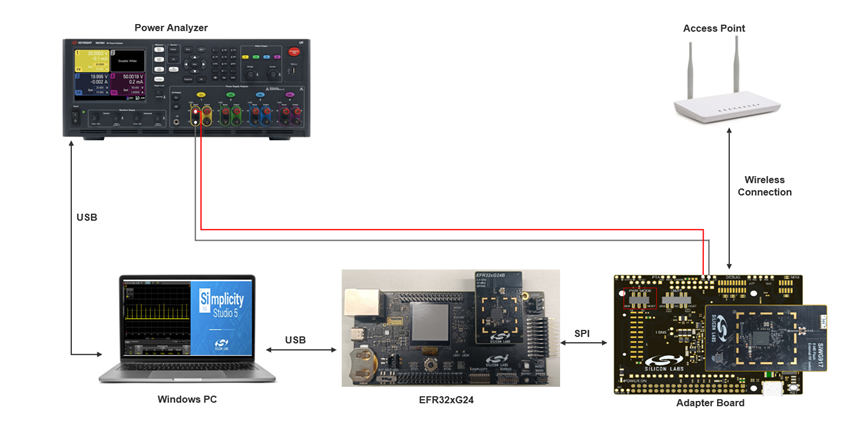
There are three ways to measure the current consumption of SiWx917 chip using the EXP Expansion Kit and EFR32xG24 +10 dBm Pro Kit.
Using Advanced Energy Monitoring (AEM) System in BRD4002A Wireless Pro Kit (WPK) Mainboard
This method does not require external instrumentation. However, being an indirect method (refer to UG569: Adapter Board for Co-Processor Radio Boards User's Guide chap 6.2), it can only be used to estimate average currents Accuracy is good enough to evaluate currents in the range of a few µA (sleep currents).
Using Current Sense Output pads of Adapter board and oscilloscope
This method is less accurate than the other methods, but it provides more bandwidth, and it might turn useful while debugging rapid changes of state, e.g., sleep-wake-sleep sequences (refer to UG569: Adapter Board for Co-Processor Radio Boards User's Guide).
Using BRD4346A Radio Board and a current meter
This method can be used to connect more sophisticated external instruments If performed correctly, it will be good to reproduce datasheet figures, However, this method is prone to induce leakage currents by the host peripheral if not correct-ly handled in firmware, hence not recommended for debugging purpose.
AEM-Based Current Measurement#
AEM is a HW feature of WPK. Energy Profiler is a graphic SW tool in the Simplicity IDE that can be used for tracing the current consumption. This method does not require any additional instruments/hardware used to measure current. In summary, it is based on two alternate current measurements read by the host board and estimates the device’s consumption as difference of the two first measurements. Therefore, this method can only be used to estimate average currents.
Refer to how to use Energy Profiler. Alternatively, AEM readings are available from command line, using Simplicity Commander instead of Energy Profiler. In this way, more options are available, e.g. setting average window and more, For more details on AEM, refer to UG525: BRD4186C User Guide.
This method is based on two current measurements and estimates the device’s current consumption as an indirect measurement.
Procedure:
Switch to Energy Profiler perspective in the Simplicity Studio IDE or open the Simplicity Commander.
Connect the EFR32xG24 WPK to the Energy Profiler in Studio.
Configure the Adapter Board in hosted Power Mode by toggling the PWR MODE switch of Adapter Board to HOST.
Power Cycle the EFR32xG24 host (which in turn resets the SiWx917 chip).
If using Energy Profiler, view the Current vs Time graph and measure average current consumption over desired duration. If using Simplicity Commander, give the appropriate command. For example, for measuring the average current over a period of 30 sec-onds, give the following command:
commander aem measure --windowlength 30000. This gives you total current consumption of host Board and the SiWx917. Refer this current as I(total).Disconnect EFR32xG24 from Energy Profiler and disconnect the EFR32xG24.
Configure the Adapter Board in hosted Power Mode by toggling the PWR MODE switch of Adapter Board to BUF.
Power up the EFR32xG24 and connect it to Energy Profiler, if using Energy Profiler.
If using Energy Profiler, view the Current vs Time graph and measure average current consumption over desired duration. If using Simplicity Commander, give the respective command to obtain current reading. This gives you current consumption of host Board alone. Refer this current as I(host).
Calculate the difference I(SiWx917) = I(total) - I(host). This gives the SiWx917's current consumption.
Current Measurement using Current Sense Output Pads of Adapter Board#
The adapter board features two analog outputs, with different gains and bandwidths, which give a direct measure of the current absorbed by the device. This method is intended for dynamic debugging, to detect quick changes of states which might not be detected with the other methods presented in this application note and it is most suitable for oscilloscopes with more than 1MHz bandwidth to capture the dynamic. For more details, refer to the UG569: Adapter Board for Co-Processor Radio Boards User's Guide.
Current Measurement Using BRD4346A Radio Board#
This method can be used to reproduce datasheet figures if correctly applied. The current measurement point is at the bottom side of the BRD4346A Radio board. Remove the R219 (0 ohms) resistor and connect the positive and negative terminals of the current measurement point to a current meter through appropriate connecting wires as shown below.
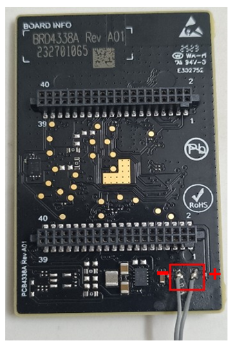

This method presents the advantage of connecting the most accurate external instruments, but it is prone to create a potential difference between the two power domains, of respectively host and device, as it introduces a resistive element between them to sense the current. If the host IOs are not tristated, the host IOs will source some current to the device, in parallel to the current meter, altering the measurements/producing invalid results.
Choosing an advanced current meter, able to track the host voltage and dynamically replicate it at the negative sense/source terminal would be a safer option. The instrument bandwidth should allow the voltage to settle based on its internal sense resistance and the board input capacitance, about 25 µF. If not sure about these parameters, the other two methods are considered safer debugging options.
The host MCU can be as per the user's choice. In this case, the EFR32xG24 host MCU is used

Current Consumption Values#
This section describes the current consumption of SiWx917 during different stages and states.
Note: The current consumption values provided in this section are just for reference purpose.
Active Mode Current Consumption#
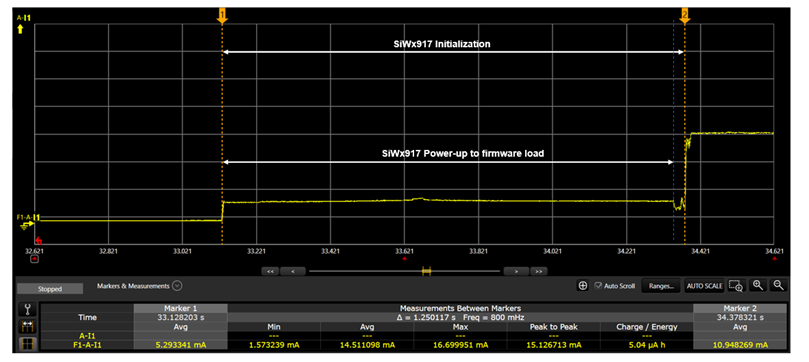
Device initialization
The following figure shows the Current vs Time graph and average current consumed in Keysight 14585A application obtained using Power Analyzer and current measurement point on BRD4346A Radio Board.

State
Average Current Consumption
Time Taken
SiWx917's Power-up to firmware load
14.59 mA
1.21 seconds
SiWx917's Power-up to radio initialization
14.51 mA
1.25 seconds
Wireless Scan
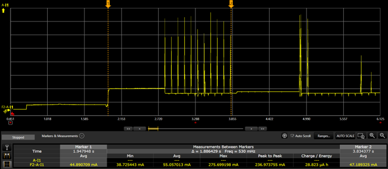
By default, the applications are configured to scan on all 2.4 GHz channels (1-11) for the specified SSID. The SiWx917 sends a directed Probe Request specifying the SSID it is looking for on all the 2.4 GHz channels. The following figure shows the Current vs Time graph and average current consumed in Keysight 14585A application obtained using Power Analyzer and current measurement point on BRD4346A Radio Board.

State
Average Current Consumption
Time Taken
Wireless Scan
55 mA
~1.1 seconds
The Quick Scan feature enables SiWx917 to scan for a particular access point in a particular channel. This feature benefits you if your application connects to a known SSID on a specific channel number. This helps in reducing the time taken for scanning for APs as well as lowers the current consumption.
Wireless Connection
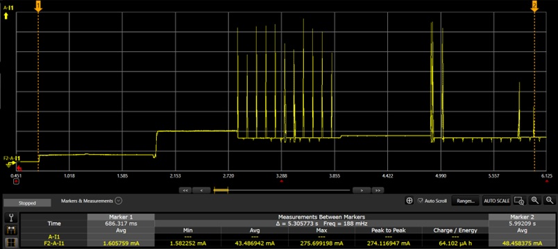
By default, the SiWx917 sends a unicast probe request, gets a probe response, and then connects to the AP.

State
Average Current Consumption
Time Taken
SiWx917's Power-up to IP Configuration
43.48 mA
~5 seconds
The Quick Join feature enables SiWx917 to send authentication and association frames without unicast probe requests. To use the Quick Join feature, enable SI91X_JOIN_FEAT_QUICK_JOIN feature in the join_feature_bitmapand call the following API:
sl_status_t sl_si91x_set_join_configuration(sl_wifi_interface_t interface, uint8_t join_feature_bitmap)
Tx Active and Rx Active Currents
The SiWx917 can be in any of the following atomic states:
TX_ACTIVE: Current consumption during active transmission at a given on-air data rate such as 6 Mbps, 11 Mbps, 54 Mbps, 72 Mbps, MCS7, etc., and a given output power level (e.g., 8 dBm, 18 dBm).
RX_ACTIVE: Current consumption during active reception at a given on-air data rate.
The above current consumption values are mentioned in WLAN 2.4 GHzsection of the SiWx917 Data Sheet.
Connect Power Save Mode Current Consumption#
DTIM-based Power Save Current
Test Configuration:
The DTIM configured in the AP is 1.
The beacon interval is set to 100 ms. In terms of 802.11 Time Units (TU), the actual beacon interval is 100 ms* 1 TU = 1024 μs. As per the above configuration, every beacon is a DTIM beacon and SiWx917 wakes every 102.4 ms. If no listen interval configurations are enabled in the application, the SiWx917 by default wakes up based on the DTIM Period.
The Average Current Consumption (measured over a period of two minutes) for DTIM Period 10 are mentioned in the 7.6.1.1 WLAN 2.4 GHzsection of SiWx917 Datasheet. The current consumption values in the Datasheet are for 352 KB RAM Retention configuration, which means the boot configuration, sl_wifi_device_configuration_t. .boot_config. ext_custom_feature_bit_map is set to SL_SI91X_RAM_LEVEL_NWP_BASIC_MCU_ADV. By default, the reference examples in the WiSeConnect SDK have 672 KB RAM Retention configuration, which means sl_wifi_device_configuration_t. .boot_config. ext_custom_feature_bit_map is set to SL_SI91X_RAM_LEVEL_NWP_ALL_MCU_ZERO.
.
Note: The SiWx917 firmware sends WLAN Keep-alive frames every 30 seconds to maintain active connection with the connected AP.
Listen Interval-based Power Save Current
Test Configuration:
The DTIM configured in the AP is 1.
Listen interval is set to 1000 ms. As per the above configuration, the SiWx917 wakes every 1000ms (every 10th DTIM beacon), which is nearest integral multiple of DTIM Period i.e., it wakes up for every 10th beacon and listens to the AP DTIM beacon frame.
The Average Current Consumption for a Listen Interval = 1000 ms is same as DTIM period = 10.
Examples:
AP DTIM is set to 3.
AP Beacon interval is 100 ms.
SiWx917's Listen interval is set to 1000 ms. As per the above configuration, then the SiWx917 wakes every 900 ms (every 3rd DTIM beacon), which is the nearest integral multiple of DTIM Period closest to the listen interval and reads to the DTIM beacon. The more the DTIM Period, the lower the SiWx917 current consumption and vice versa.
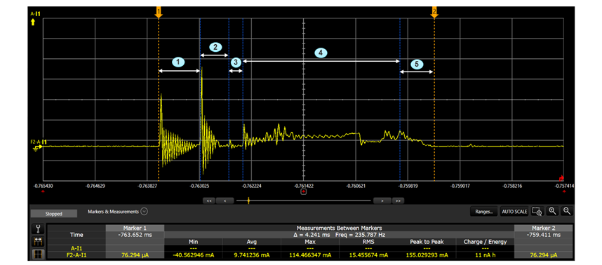
Beacon Current Profile
When in Connected Power Save Modes, the SiWx917 listens to beacons after every DTIM period or listen- interval elapses. The following depicts the current consumption and time taken at different stages while receiving a beacon.
The following table illustrates the beacon current profile at various stages:

State
Average Current Consumption
Time Taken
Power Management Unit (PMU) Time
2.5 mA
635 μs
Crystal good Time
7 mA
443 μs
NWP and Wireless Modem Power up
1 mA
210 μs
Wireless Modem receiving a beacon in listen mode
13.2 mA
2.4 ms
NWP and Wireless Modem shut down and sleep mode
7.8 mA
457 μs
Typical Wake/Sleep Timings#
Test Configuration:
Connect SiWx917 to an AP.
Set SiWx917 in Connected Power Save.
Transmit a UDP data packet.
For sending a UDP packet, the WiSeConnect SDK driver internally sends two commands: socket create request and socket data send.
After each command, the host gives sleep permission to SiWx917 by de-asserting the respective GPIO.
In this case, after sending socket create request command, the host gives sleep permission to SiWx917. By the time, the SiWx917 goes to sleep, the host makes another wake request, during which time it notices that the SiWx917 is still in wake state and sends the socket data send command.
The following figure illustrates the amount of time taken by SiWx917 to go to sleep or wake up upon a host's request.


State
Time Taken
Time taken to Wake
2 ms
Time taken to Sleep
1 ms
The following figure illustrates the amount of time taken by SiWx917 to go to sleep or wake upon a host's request.


