Getting Started with WiSeConnect SDK and EFR32 Host in NCP Mode#
This guide describes how to get started with developing an application for the SiWx91x™ chipset family using the WiSeConnect™ SDK with an EFR32™ host in Network Co-Processor (NCP) mode, where the application runs on the EFR32 host and the connectivity stack runs on the SiWx91x chipset.
Note: The output images in this guide are for illustration purposes only. Details such as board names and version numbers may not exactly match the product.
Check Prerequisites#
Note: The software and hardware requirements mentioned in this section are specific to the example(s) recommended with this guide in the Create a Project section. If you are working with a different example, refer to its README page for the software and hardware requirements. To see the README page of a specific example, click on the Go to README link next to it in the Examples page.
Software#
Simplicity Studio 6
GNU ARM v12.2.1 Toolchain
Simplicity software development kit (SiSDK (formerly GSDK)) with WiSeConnect extension
VS Code with Simplicity Studio for VS Code extension (Version 1.6.1 or higher)
Note: We recommend to use the latest Simplicity Studio and SiSDK (formerly GSDK) versions.
Hardware#
Wi-Fi Access Point (802.11 b/g/n/ax)
BRD4002A - Si-MB4002A Wireless Pro Kit Mainboard (hereafter referred to as WPK board)
One of the following Host radio boards (hereafter referred to as EFR32 radio boards)
SIWX917-RB4346A - SiWx917 Wi-Fi 6 and Bluetooth LE 4MB Flash Co-Processor Radio Board (hereafter referred as BRD4346A in this document (hereafter referred to as SiWx917 radio board).
SIWX917-RB4357A - SiWN917Y Module Wi-Fi 6 and Bluetooth LE 4MB Flash RF-Pin Co-Processor Radio Board (hereafter referred to as SiWx917 radio board).
SI-EB8045A - EXP Adapter Board for Co-Processor Expansion Kit (hereafter referred to as adapter board).
Windows/Linux/MacOS computer with a USB port
Two type C USB cables compatible with the computer's USB port (for e.g., type C to type A if the computer has a type A USB port)
Setup Software#
You can set up the following software in this section without having the hardware available.
Install Simplicity Studio#
This section describes the following installation methods for Simplicity Studio 6:
Install from Scratch when you are installing Simplicity Studio for the first time.
Upgrade from the Demo-only Studio Edition when you have previously run a Studio demo as described in Run the Demo with Simplicity Studio.
Install from Scratch#
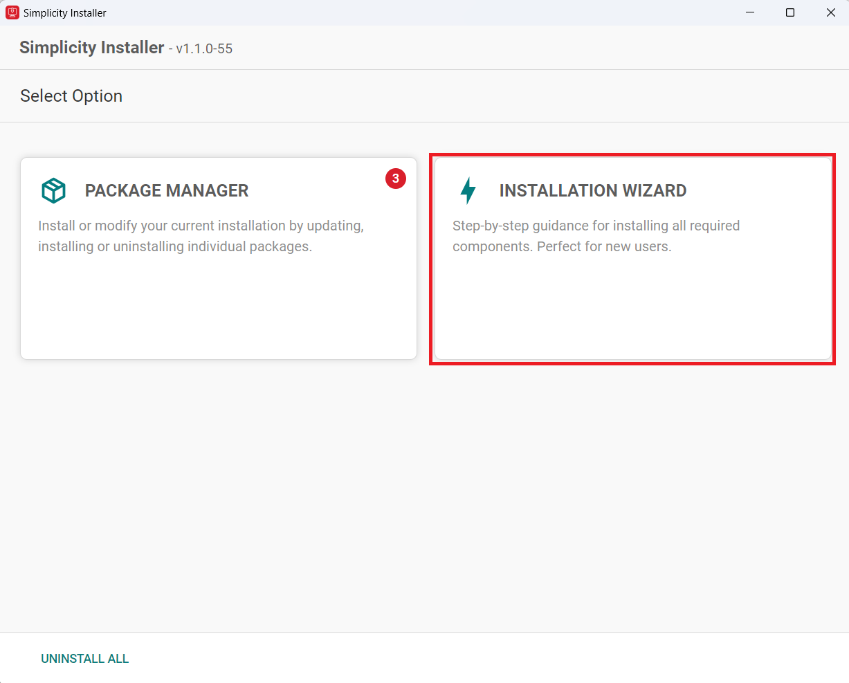
Download the latest version of Simplicity Installer and follow the installation instructions.
During the installation, make the following selections:
Select INSTALLATION WIZARD option.
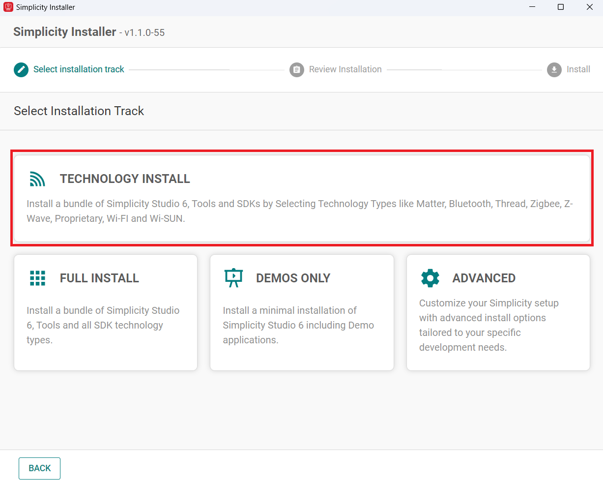
Select TECHNOLOGY INSTALL.
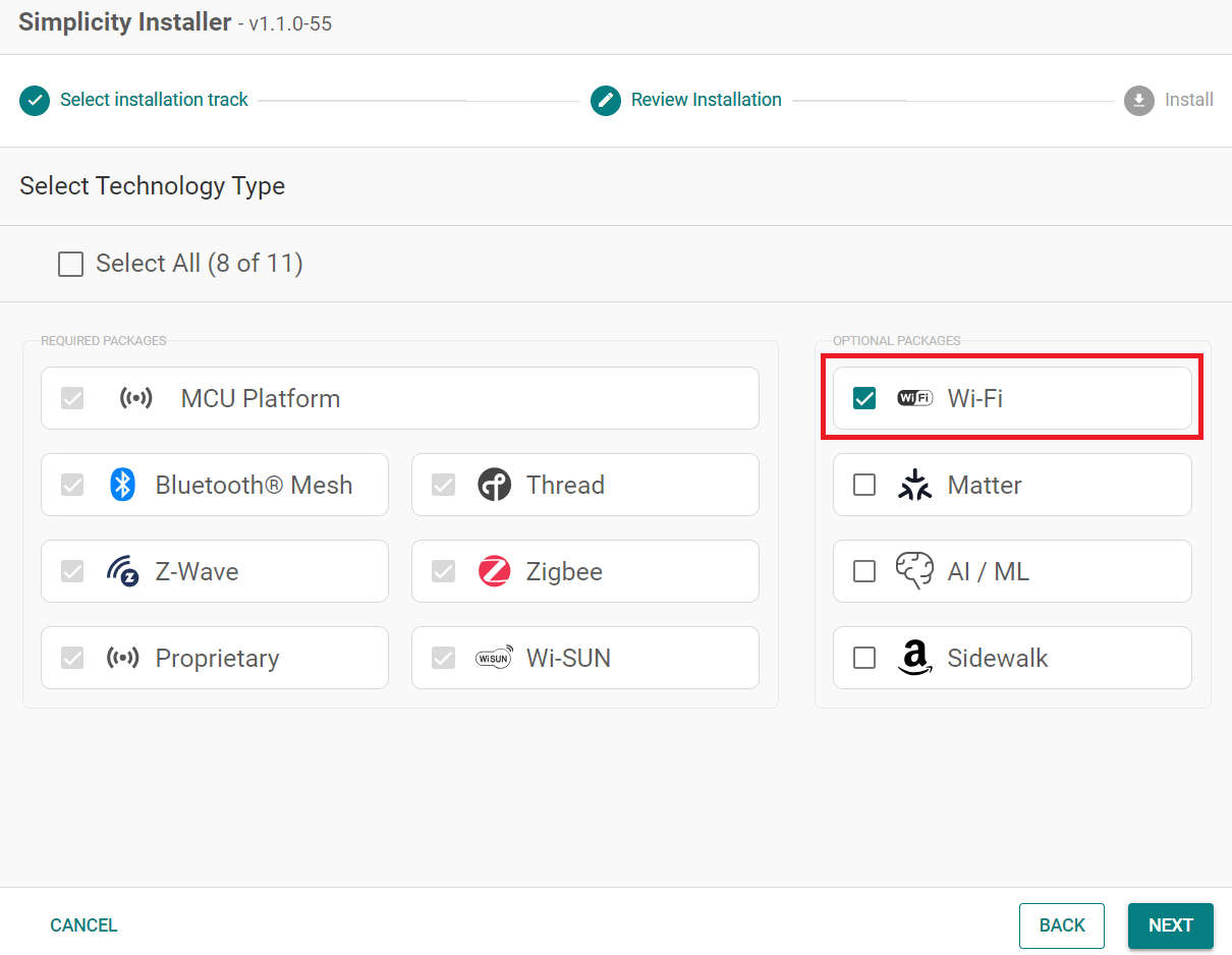
Select the Wi-Fi option.
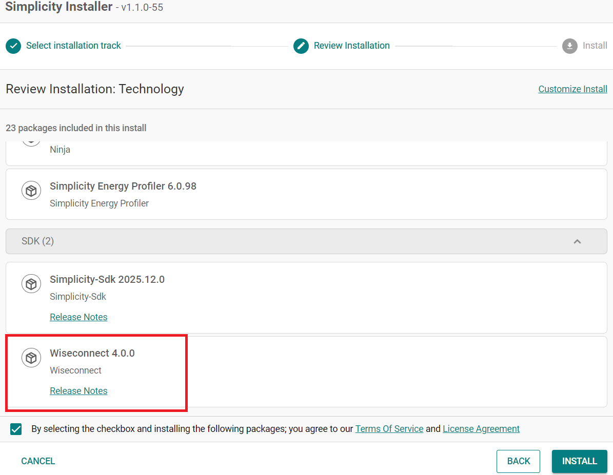
Click Next and make sure Wiseconnect is shown under the SDK that needs to be installed.
Upgrade from the Demo-only Studio Edition#
If you have installed the demo version using the option shown below:
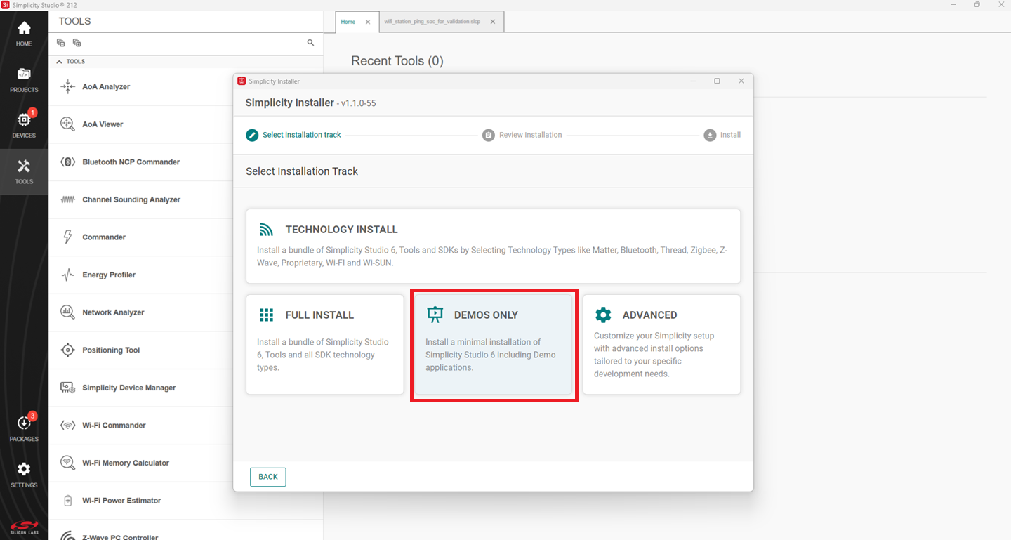
Continue from step 2 in the Install from Scratch section.
Install the GNU ARM v12.2.1 Toolchain#
Note: From v4.4.0 on, Simplicity SDK (SiSDK, formerly Gecko SDK/GSDK) requires v12.2.1 of the GNU ARM toolchain to compile a project successfully.
Launch the Simplicity Installer.
Click on the Advanced option.
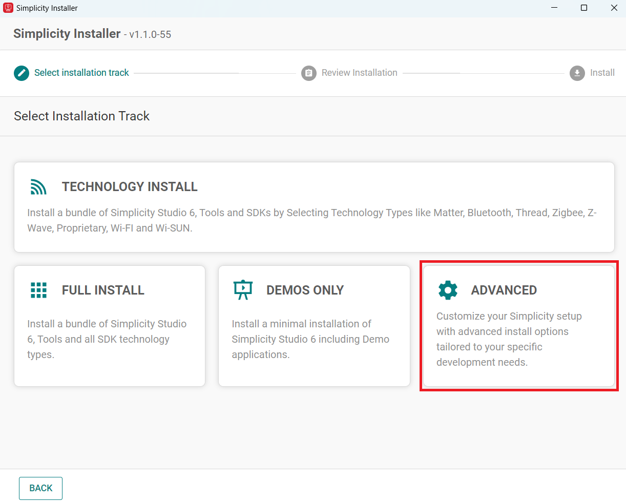
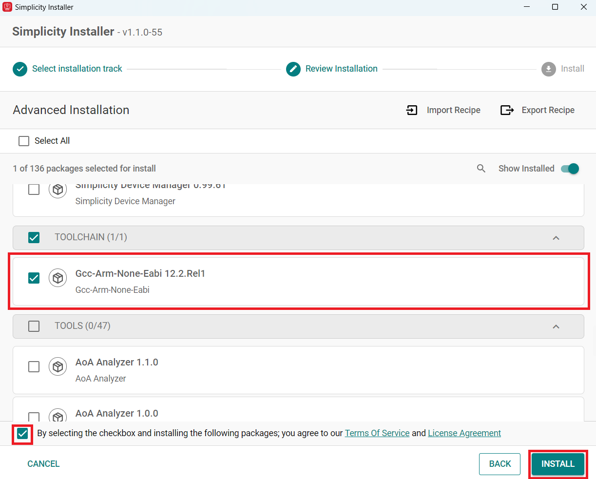
Select Gcc-Arm-None-Eabi 12.2.Rel1.
Check the box and click install.
Note: This is installed by default with the studio if you do a FULL INSTALL.
Note: If you have an existing project, see the Silicon Labs community page for instructions to configure the toolchain version in your project.
Install the WiSeConnect Extension#
If you already selected the WiSeConnect extension in the Install Simplicity Studio section, you may skip this section.
Before installing the WiSeConnect extension, upgrade to a compatible SiSDK (formerly GSDK) version if not already done. See the Prerequisites section for the supported SiSDK (formerly GSDK) versions.
You can install WiSeConnect using one of the following methods:
Install from Scratch (recommended)
Install WiSeConnect from settings#
Note: Make sure that you use SiSDK and WiSeConnect SDK versions from the same release. To determine which SiSDK and WiSeConnect SDK versions are in a particular release, see the Compatible Software section of Release Notes.
Download the WiSeConnect source code from the following URL after substituting x.x.x with the desired release version:
https://github.com/SiliconLabs/wiseconnect/archive/refs/tags/vx.x.x.zipIf you don't know your release version, go to the GitHub Releases Page and select the version to download.
Unzip the downloaded
wiseconnect-x.x.x.zipfile. It will be extracted into a folder structure similar to the following:wiseconnect-x.x.x |--- wiseconnect-x.x.x |------ <source code>Launch Simplicity Studio.
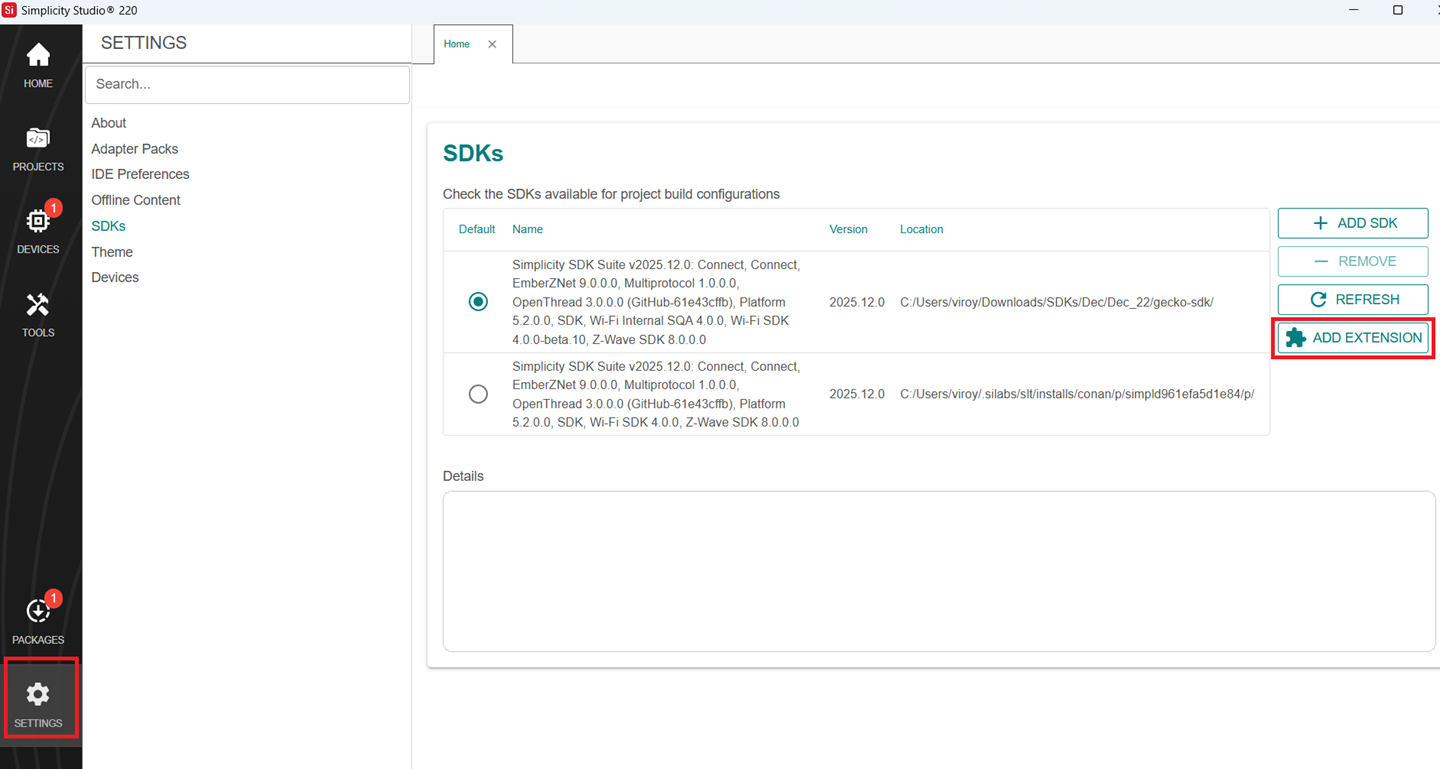
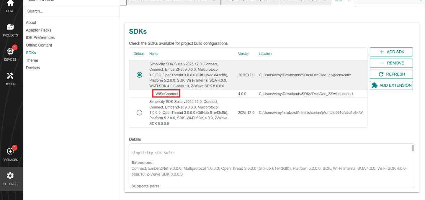
In the Simplicity Studio home page, go to SETTINGS and select the SDKs tab.
Select Simplicity SDK (formerly Gecko SDK) Suite vx.x.x and click ADD EXTENSION.
In the Add SDK Extensions window, click Browse.
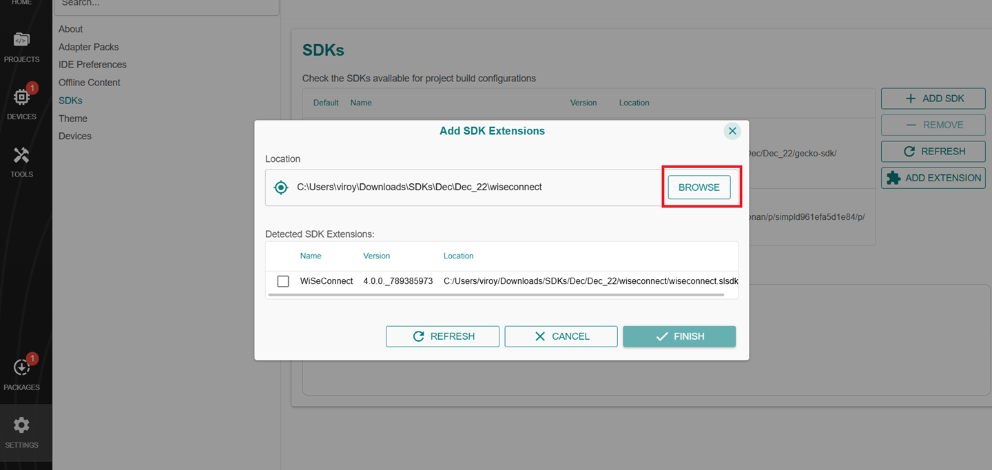
Locate and select the
wiseconnect-x.x.xsub-folder extracted in step 2 above which contains the source code.Studio will detect the WiSeConnect SDK extension.
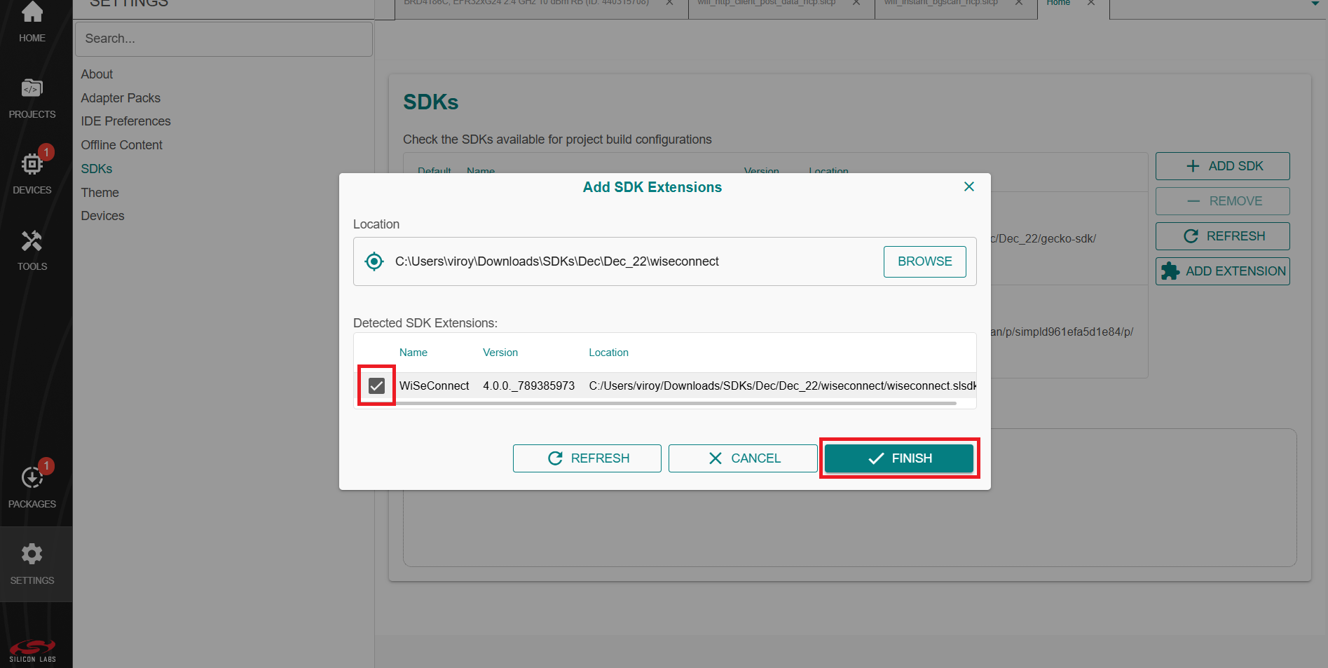
Select the detected extension and click FINISH.
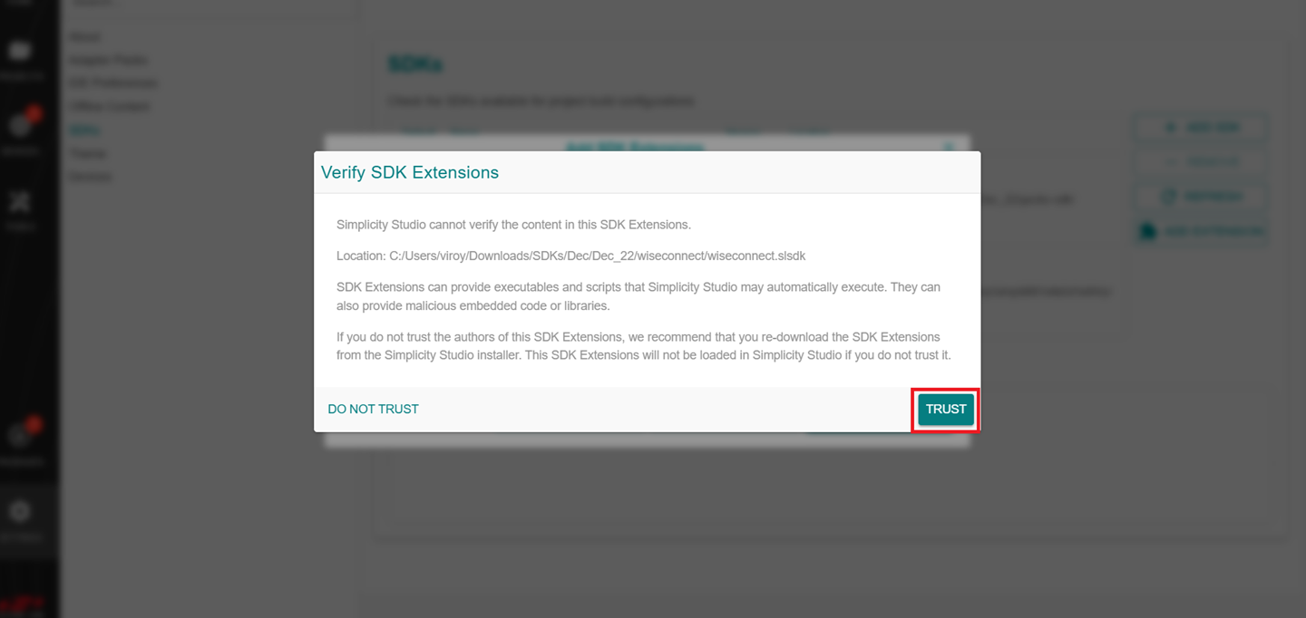
If a Verify SDK Extension pop-up is displayed, click Trust.
The selected WiSeConnect extension will be displayed.
Click REFRESH and navigate to HOME or PROJECTS.
Install the VS Code Extension#
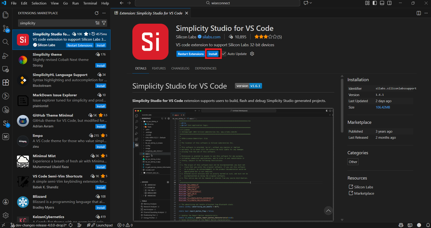
Navigate to the Extensions tab in VS Code and search for Simplicity Studio for VS Code extension.
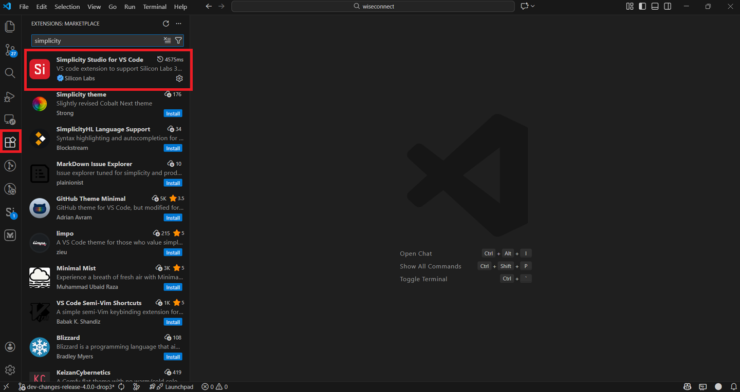
Install the extension.
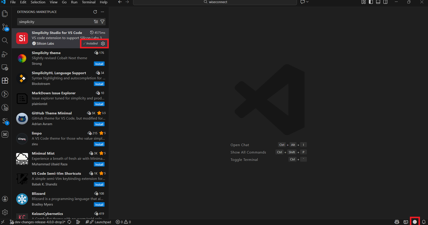
Once the extension is installed and restarted, it will automatically detect the studio.
Note: This can be confirmed once the circle at the bottom right corner turns white.
Connect the Boards to a Computer#
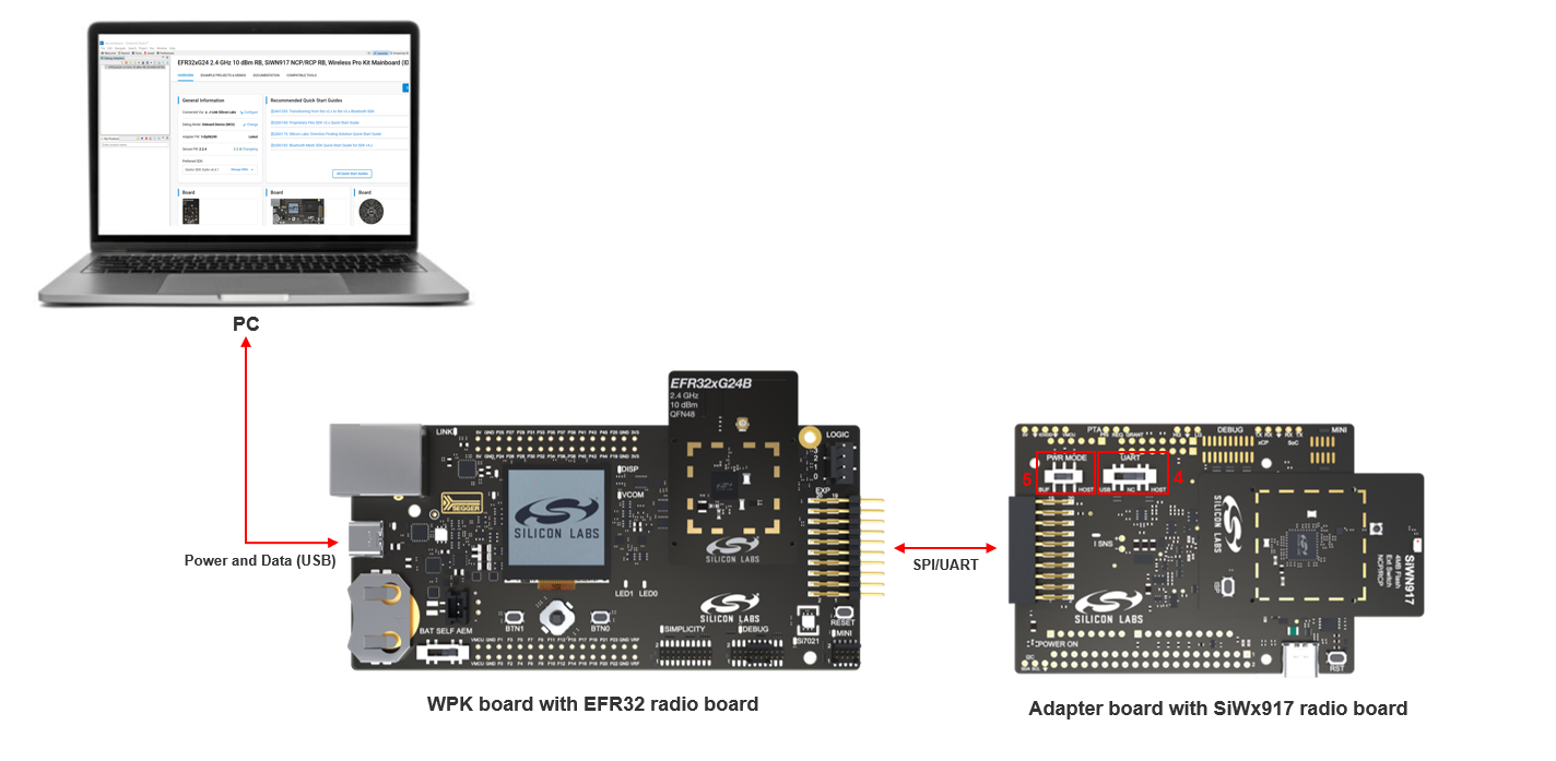
Plug the EFR32 radio board into the radio board connectors of the WPK board as shown below.
Plug the SiWx917 radio board into the radio board connectors of the adapter board as shown below.
Connect the adapter board to the EXP header on the EFR32 WPK board.
Make sure the UART switch on the adapter board is in the correct position depending on the type of interface between the SiWx91x device and the external MCU host:
For a serial peripheral interface (SPI), the switch must be in the USB position.
For a universal asynchronous receiver-transmitter (UART) interface, the switch must be in the HOST position.
Note: For a universal asynchronous receiver-transmitter (UART) interface:
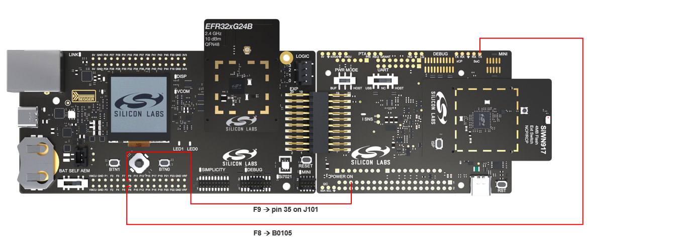
Connect the hardware flow control pins as shown below:
BRD8045A Adapter board
EFR32 WPK board GPIO Breakout Pad
B0105 (RTS)
F8/EXP3 (CTS)
pin #35 on J101 (CTS)
F9/EXP5 (RTS)
Define the
SL_SI91X_UART_HIGH_SPEED_ENABLEandSL_SI91X_UART_HFC_ENABLEmacros to enable Hardware Flow Control.
Make sure the PWR MODE switch on the adapter board is in the BUF position.
Connect the EFR32 WPK board to your computer using a type C USB cable.
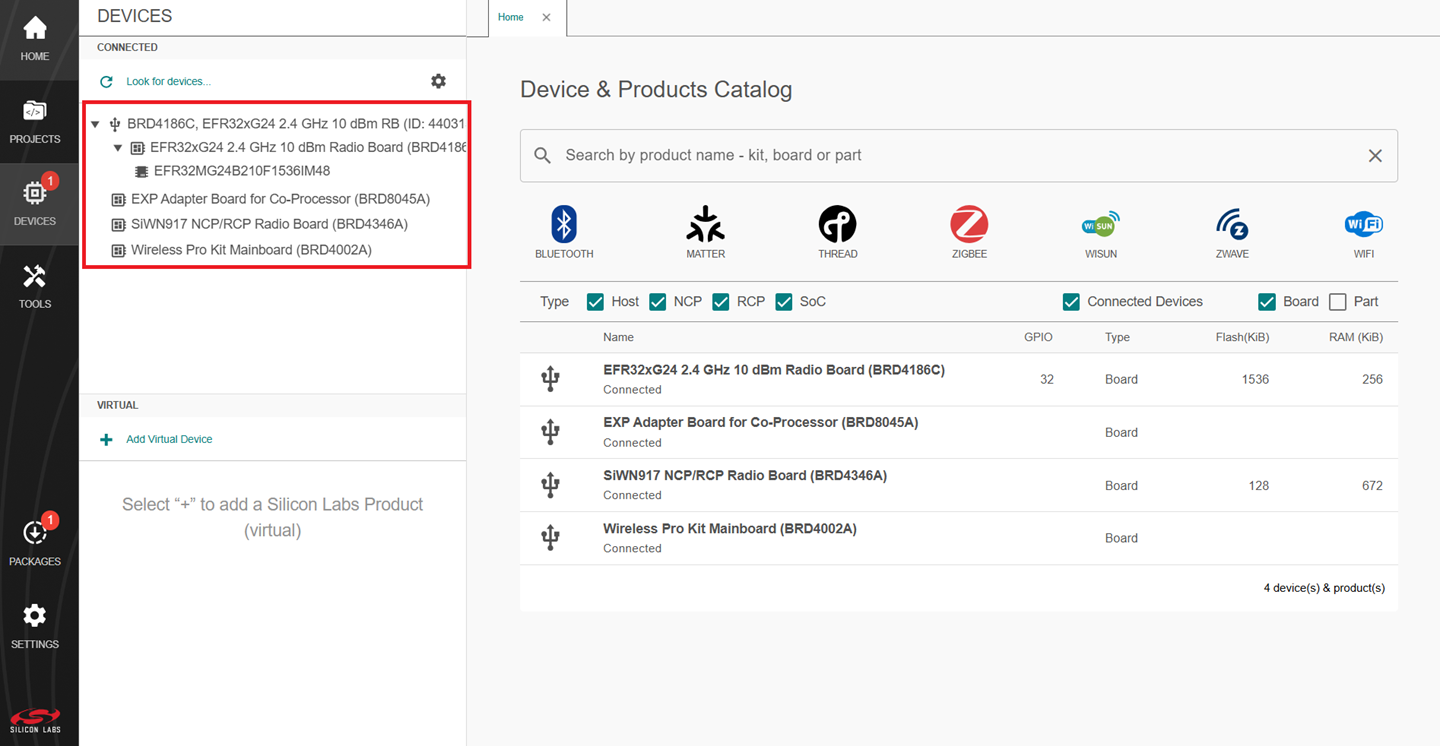
Simplicity Studio will detect and display your EFR32 radio board.
Troubleshoot Board Detection Failure#
If Simplicity Studio does not detect your EFR32 radio board, try the following:
In the DEVICES pane, Click the Look for devices button (having an icon of a looping arrow).
Reset both the WPK board and adapter board by pressing the RESET button and RST button on the corresponding boards.
Power-cycle the EFR32 radio board by disconnecting and reconnecting the USB cable.
Update SiWx91x Connectivity Firmware#
Note: The SiWx917 connectivity firmware version is tightly coupled with the WiSeConnect extension version. You must update the SiWx917 connectivity firmware when:
You first receive an SiWx917 EXP expansion kit
You first receive an SiWx917 co-processor radio board, or
You upgrade or downgrade your WiSeConnect extension
There are two supported methods for updating the SiWx917 connectivity firmware:
Firmware Update via UART: This method utilizes the SiWx917's UART interface and typically requires approximately 2 minutes to complete the update when operating at a baud rate of 921600 bps.
Firmware Update via SPI: This method leverages the SiWx917's SPI interface and offers significantly faster performance, completing the firmware update in approximately 16 seconds when operating at a SPI clock frequency of 10 MHz.
Firmware Update via UART#
In this method, the SiWx917 NCP's UART (UART1) is used for firmware update. Follow the below sequence of steps to update the firmware.
Plug the SiWx917 radio board into the radio board connectors of the adapter board as shown below:
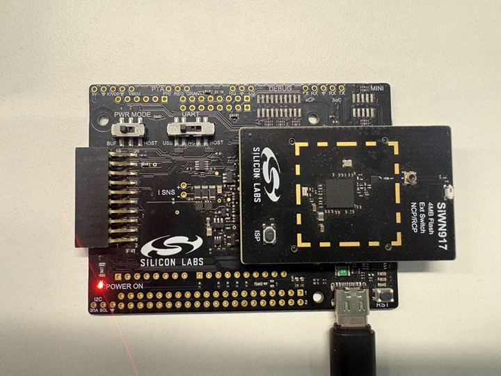
Make sure the UART switch on the adapter board is in the USB position.
Make sure the PWR MODE switch on the adapter board is in either the BUF or HOST position.
Connect the adapter board to the EFR32 WPK board.
Connect the EFR32 WPK board to your computer using a type C USB cable.
Connect the USB port of the adapter board to your computer's USB port using a type C USB cable.
In the Simplicity Studio home page, click TOOLS.
In the TOOLS tab, select Commander and click Open Tool.
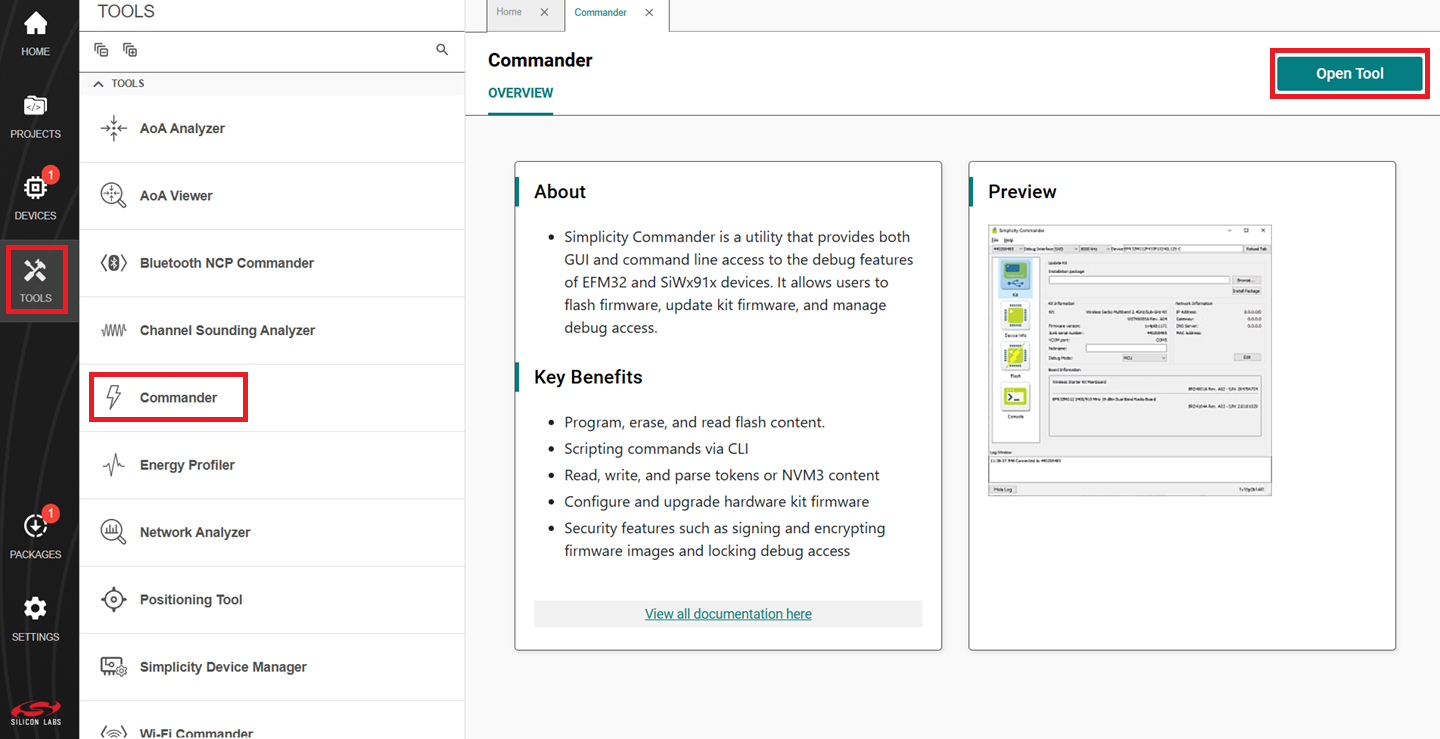
The Simplicity Commander window is displayed.
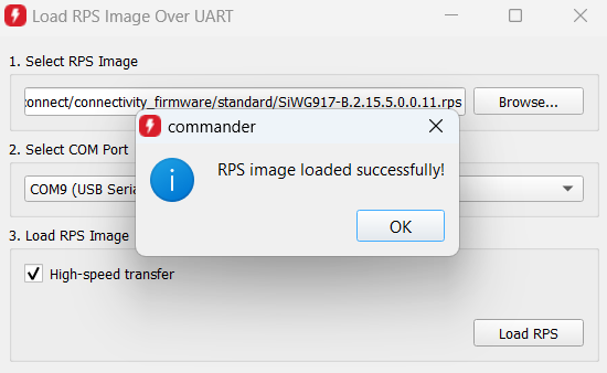
In the Simplicity Commander window, select Utilities > Load RPS Image Over UART....
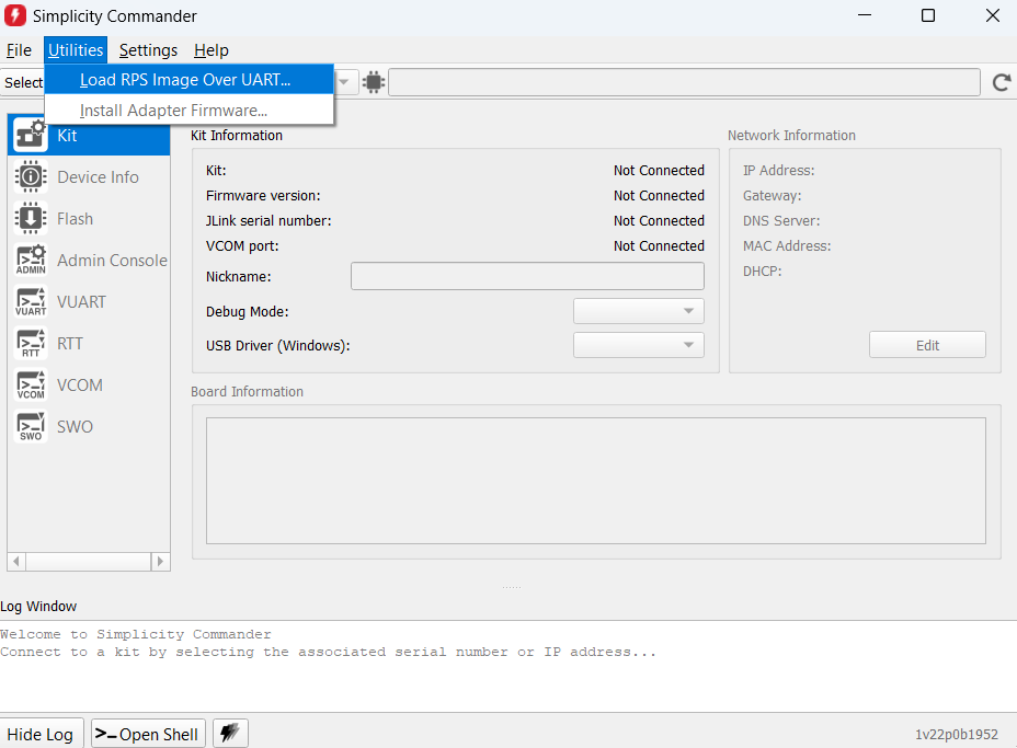
The Load RPS Image Over UART window is displayed.
Click Browse next to the Select RPS Image field.
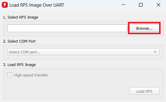
Locate and select the firmware file to flash from within the
connectivity_firmware/standardsub-folder of the WiSeConnect extension path.Note:
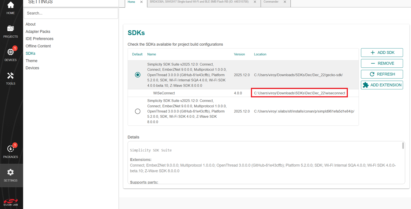
The
connectivity_firmware/litesub-folder can be ignored since the Lite OPN is not supported in NCP mode.The WiSeConnect extension path is where the extension was downloaded during installation. If you're not sure what the path is, refer to the location in the SETTINGS > SDKs page.
Under Select COM Port, select the COM port for the connected adapter board.
Under Load RPS Image, make sure High-speed transfer is selected.
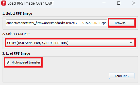
Note: When High-speed transfer is selected, Simplicity Commander sets the baud rate to 921600 before performing the firmware update.
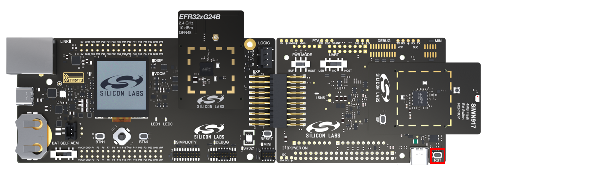
Press the RST button on the adapter board.
Click Load RPS to update firmware.
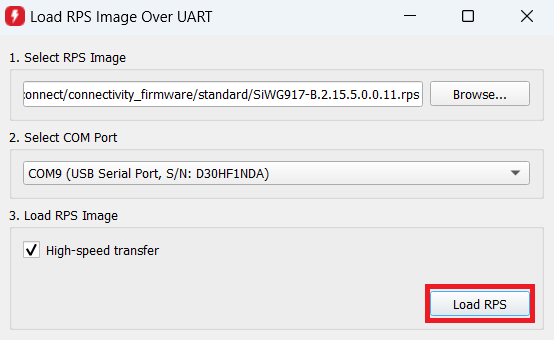
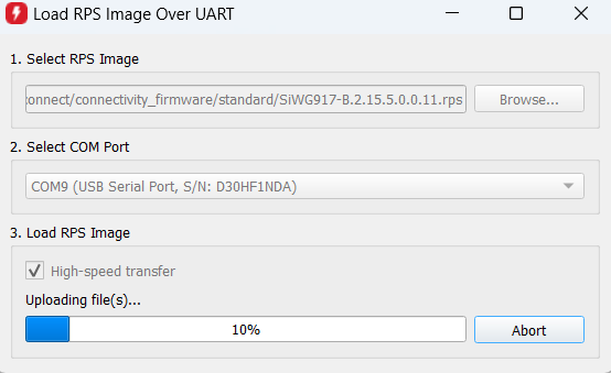
Note: It takes around 2 minutes to perform a firmware update.
On successful firmware update, the following message is displayed: "RPS image loaded successfully!".
Firmware Update via SPI#
In this method, the firmware update is performed over the SiWx917's SPI interface. It involves two main processes.
SPI Bridge Application flashing: First, flash a prebuilt SPI bridge application binary onto the EFR32 host MCU. This application acts as a communication bridge between the host and the SiWx917.
Firmware Transfer via SPI: Once the SPI bridge is operational, it facilitates the transfer of the SiWx917 connectivity firmware—provided by the user—over the SPI interface to the SiWx917 NCP.
Note: This method requires Simplicity Commander v1.18 ("1v18p...") or above.
The following sequence of steps should be followed to execute the update.
Download and extract the EFR32's SPI bridge application binary on your local PC.
Make the setup as mentioned in Connect the Boards to a Computer section.
In the Simplicity Studio IDE, go to Tools > Commander > Open Tool.
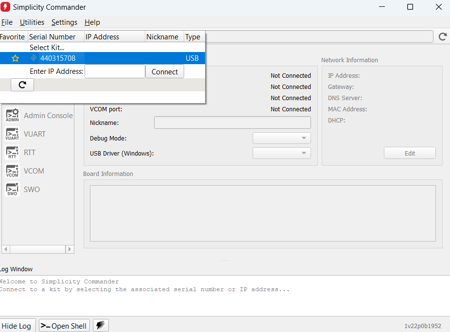
The Simplicity Commander window is displayed.
Go to Help > About Simplicity Commander and check the commander version.
Note:
If the version is below v1.18 (shall be displayed as "1v17p...")), install the latest standalone simplicity commander from here.
After installation, run the "commander.exe".
The Simplicity Commander window is displayed.
In the Simplicity Commander window, go to Select Kit.. and click the connected WPK board's serial number.
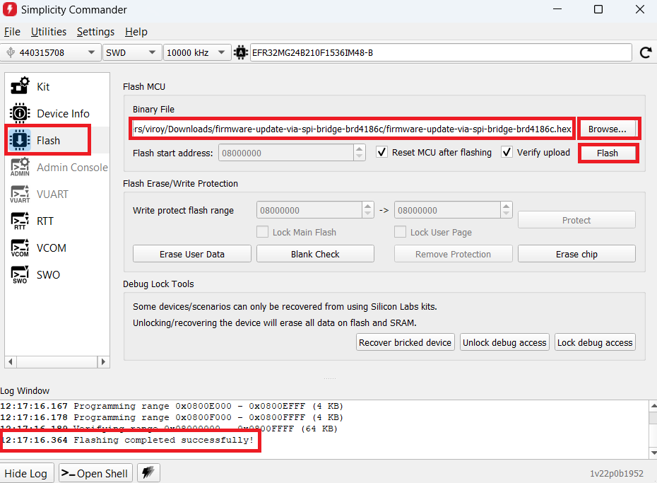
Go to Flash section.
Click Browse.
Browse to EFR32's SPI bridge application binary downloaded in step 1 and click OK.
Click Flash.
The application binary will be successfully flashed to EFR32.
Navigate to the Simplicity Commander installation path in your local PC and launch the commander CLI.
If you are using Simplicity Commander from the Simplicity Studio IDE installation, navigate to the following path within the Simplicity Studio installation directory and enter "cmd" to open the Commander CLI.
C:\SiliconLabs\SimplicityStudio\v5\developer\adapter_packs\commander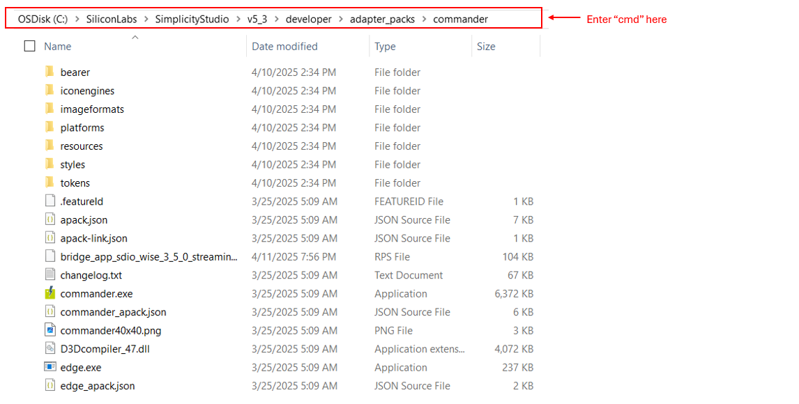
If you are using Standalone Simplicity Commander, navigate to the following path within the Simplicity Commander installation directory and enter “cmd” to open the Commander CLI.
<directory name>\SimplicityCommander\Commander_win32_x64_1v16p14b1705\Simplicity Commander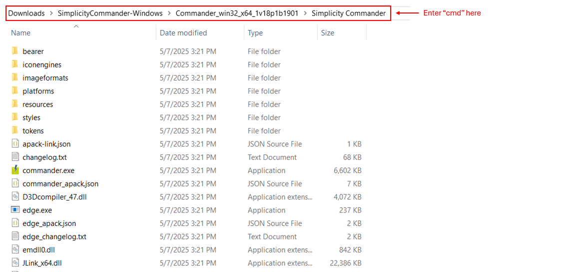
Copy the SiWx917 connectivity firmware to the same commander path mentioned in step 12. If you are not sure, where the firmware is located, refer to Note mentioned in step 13 of Firmware update via UART interface section.
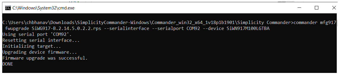
Give the following command in the CLI to trigger firmware update.
commander mfg917 fwupgrade <SiWx917 connectivity firmware file name> --serialinterface --serialport <COM Port of connected WPK board> --device <complete SiWx917 NCP part number>For example:
commander mfg917 fwupgrade SiWG917-B.2.14.5.0.2.2.rps --serialinterface --serialport COM92 --device SiWN917M100LGTBANote:
The firmware is transferred from CLI to EFR32 via UART interface at a fixed baud rate of 2537500 bps.
It takes around 16 seconds to perform a firmware update.
On successful update, the following message is displayed: "Firmware upgrade was successful.".
Create a Project#
Connect the EFR32 and SiWx917 boards to your computer.
Go to the DEVICES section.
Select the detected EFR32xG24 radio board from the displayed list.
Note: If you don't have the EFR32 radio board or you have not connected it to your computer, you may still view and create the example projects from the DEVICES tab:
Click on the DEVICES tab.
Click on Add Virtual Device.
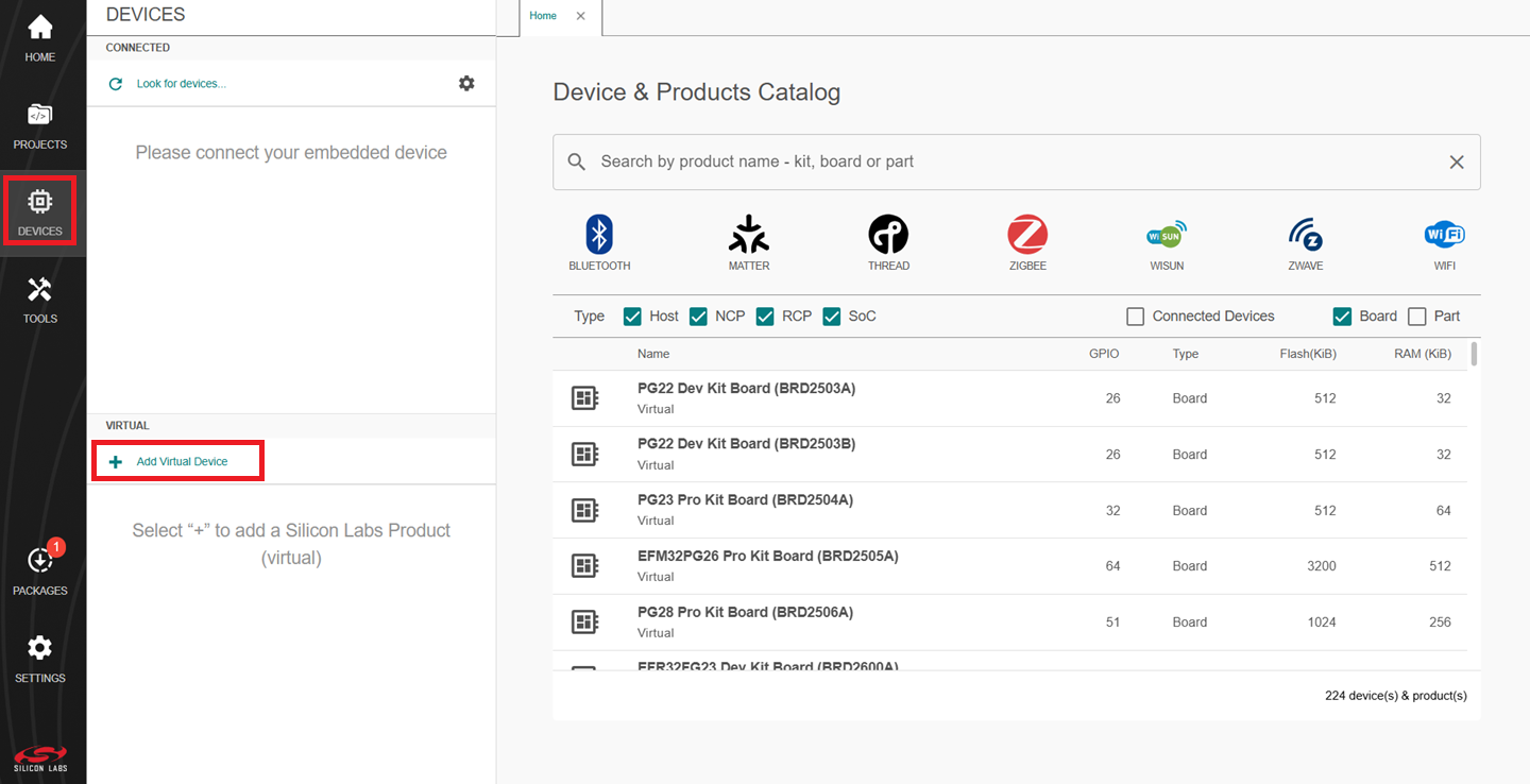
In the search tab, search for EFR32xG24 and click your desired board.
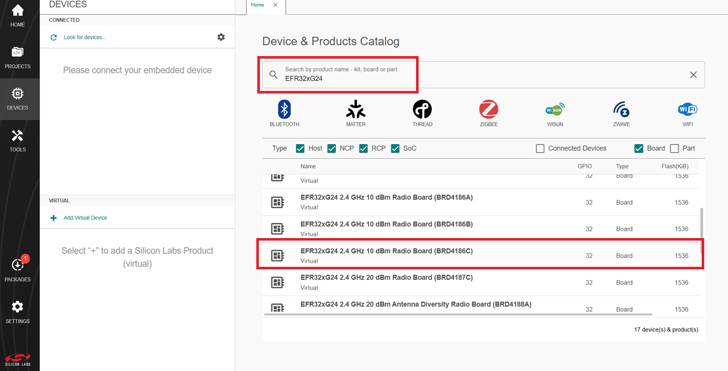
The selected board will be displayed under the VIRTUAL tab.
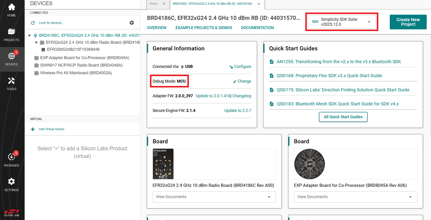
The Launcher page will display the selected radio board's details.
Select the OVERVIEW tab.
Verify the following in the General Information section:
The Debug Mode is Onboard Device (MCU).
The Preferred SDK is the version you selected earlier.
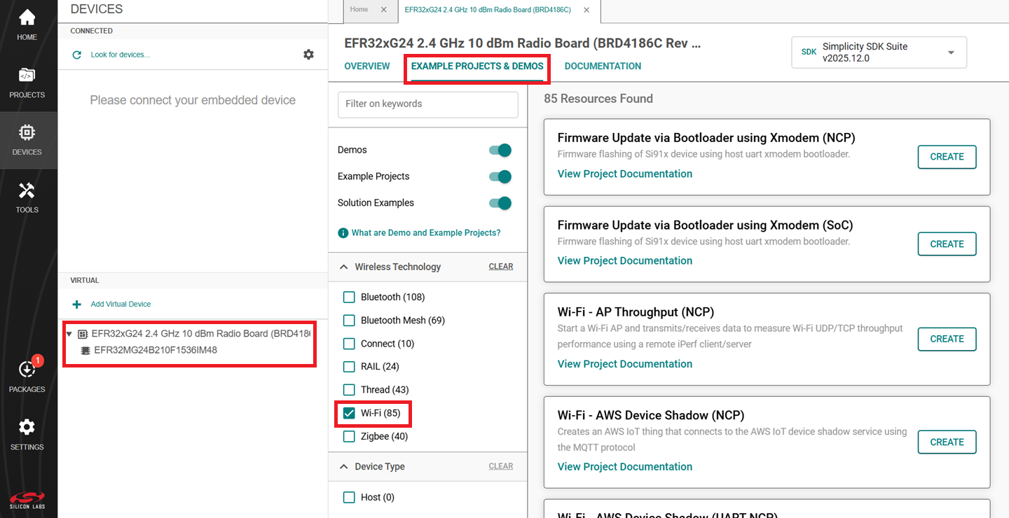
Select the EXAMPLE PROJECTS AND DEMOS tab.
Locate the example you want and click CREATE.
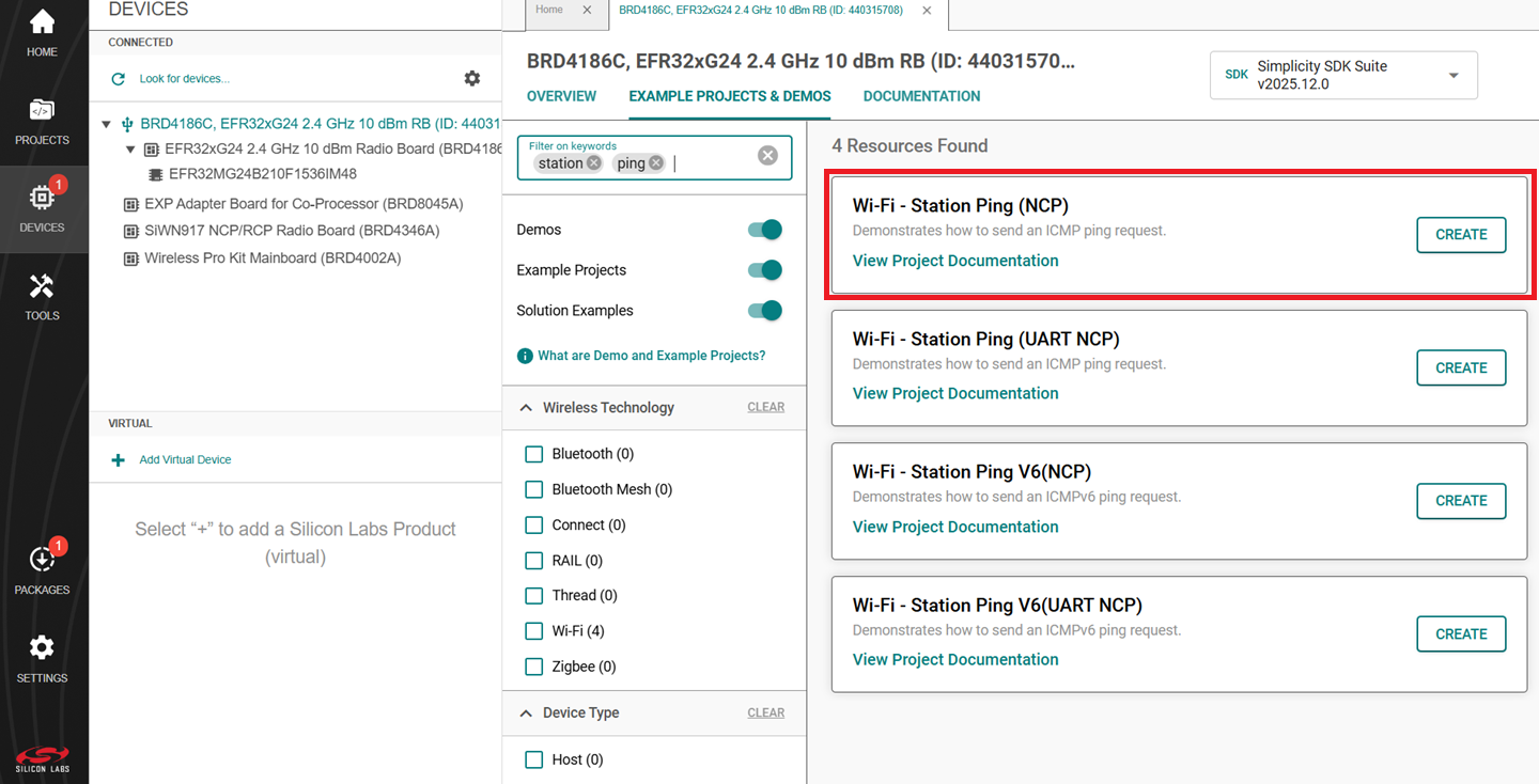
Note:
The following example is recommended for your first project, depending on the type of host connection:
Wi-Fi - Station Ping (NCP) - For connection over SPI
Wi-Fi - Station Ping (UART NCP) - For connection over UART
In the Project Configuration window, click FINISH.
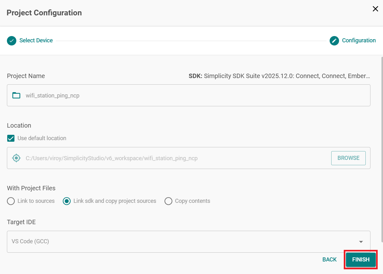
Note: Refer to the Purpose/Scope section in the README, and Overview section (not present in some README's) for more information about the example.
Configure an Application#
Configure the settings for your example, as described in the Application Build Environment section in the README page of your example.
Note:
You may use the Component Editor to configure the components in your example.
You may use the Pintool to configure the pin mappings in your project for your SiWx917 system-on-chip.
Build an Application#
Note: If you upgraded from a SiSDK (formerly GSDK) version earlier than v4.4.0, upgrade your GNU ARM Toolchain. See the GNU ARM v12.2.1 Toolchain section.
See here for the instructions to build an application.
Console Input and Output#
The method for exchanging data with the EFR32 host depends on the type of interface between the EFR32 host and the SiWx91x device.
Console Input and Output with a SPI Interface#
Connect your EFR32 and SiWx91x boards to your computer.
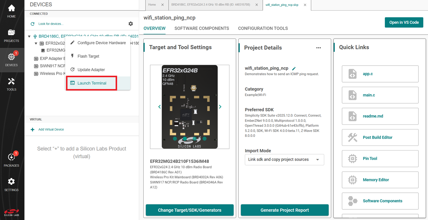
Open Simplicity Studio.
In the TOOLS tab, right-click on your radio board and click Launch Terminal.
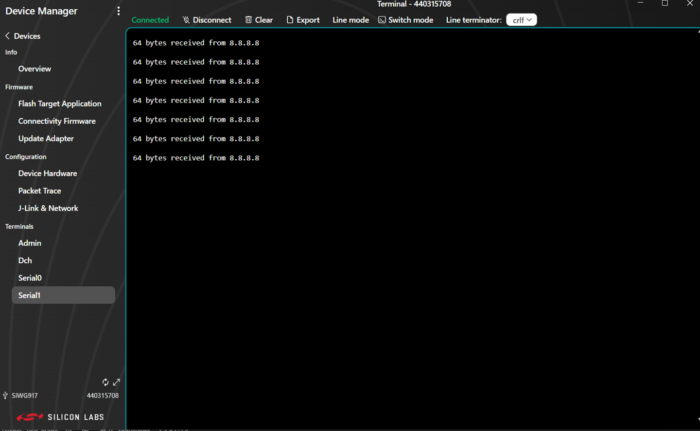
Select the Serial 1 tab.
Place the cursor inside the text input field and hit Enter.
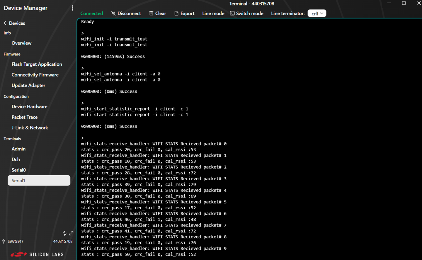
This completes the console setup for SPI interface. After you flash and run the application, the console output will start getting displayed in the Serial 1 tab.
Console input can be entered and sent to the device.
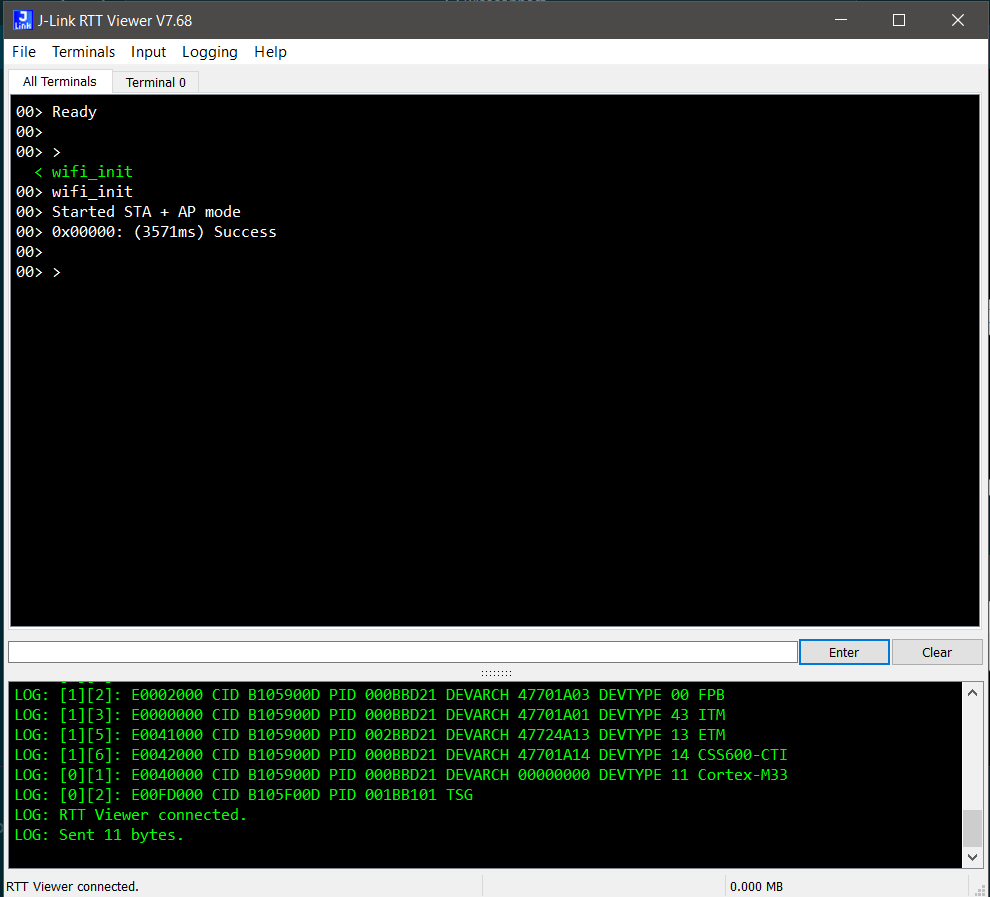
Console Input and Output with a UART Interface#
Download and install J-Link Sofware from https://www.segger.com/products/debug-probes/j-link/tools/rtt-viewer/.
Connect your EFR32 and SiWx91x boards to your computer.
Before we start streaming the logs over RTT, make sure you have entered the desired execution mode.
Using Flash an Application:
RTT can connect to the device after the application is flashed onto the device.
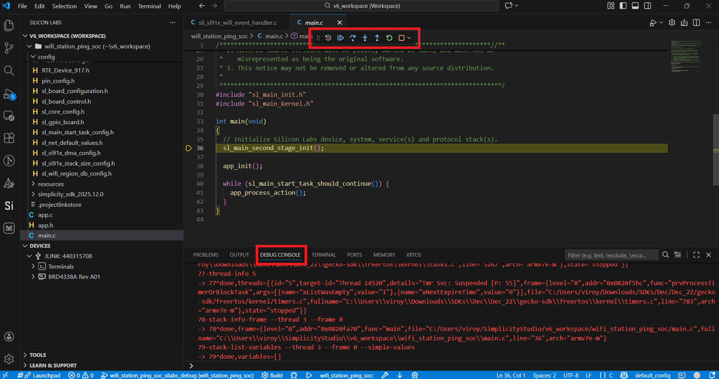
Using Debug an application:
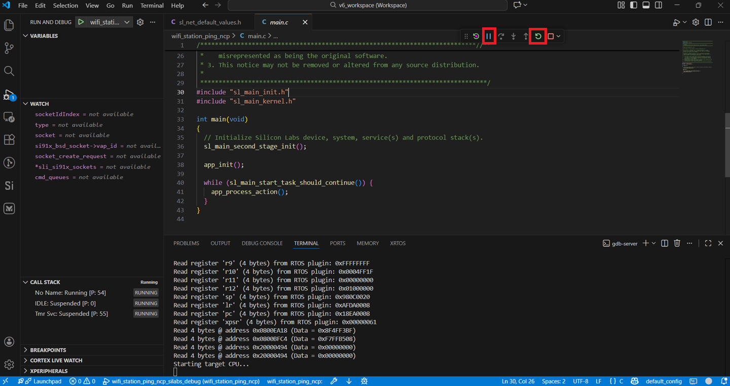
If the application is executed in "Debug" mode, first we must enter the debug window and step over the
sl_main_second_stage_init();function so that the RTT block is initialized for logging as shown below.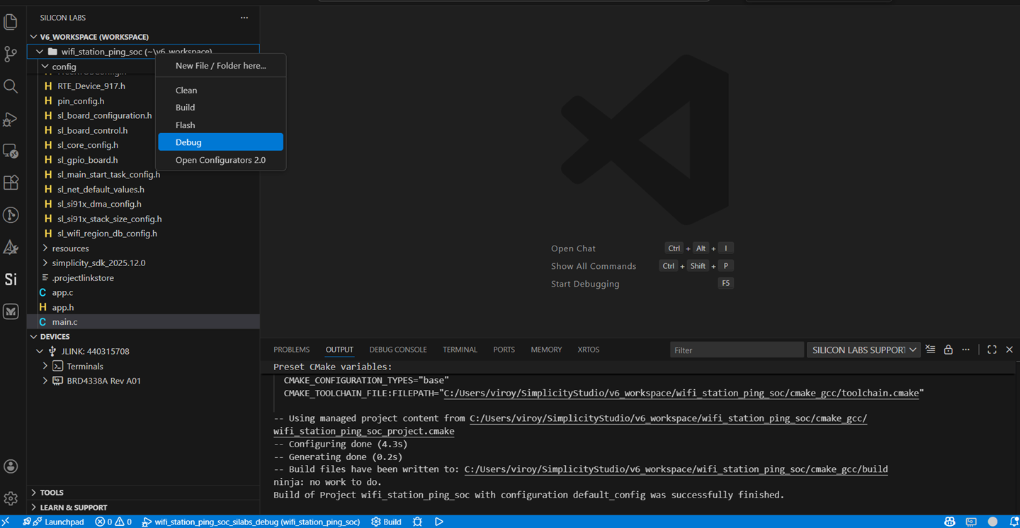
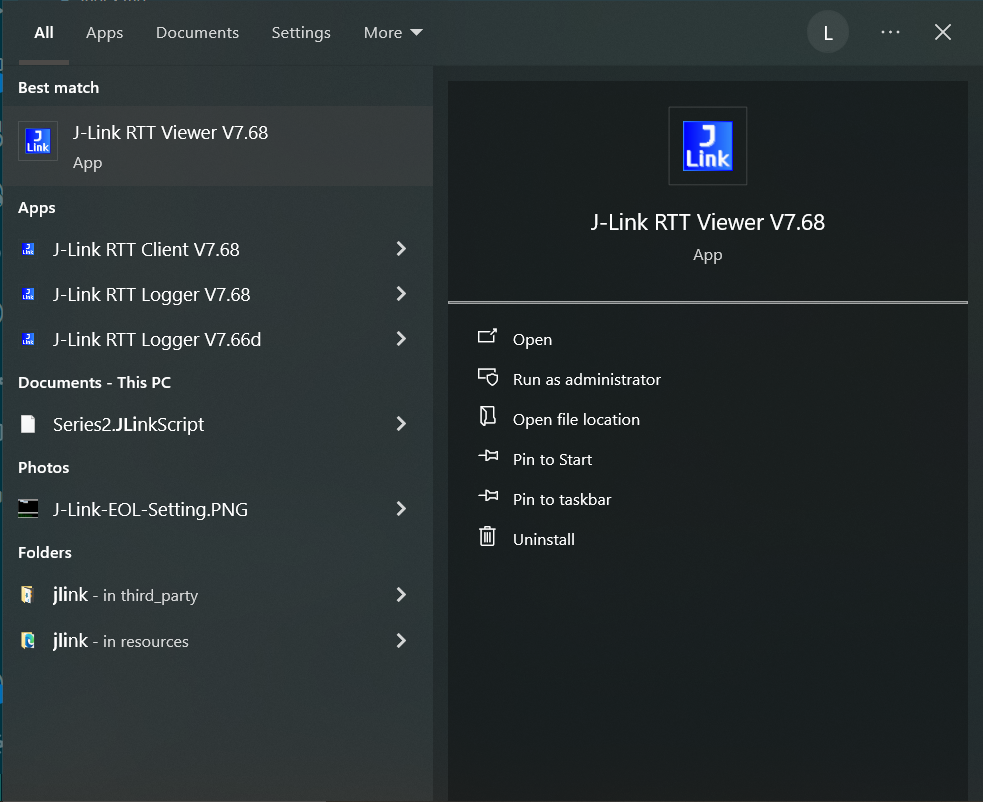
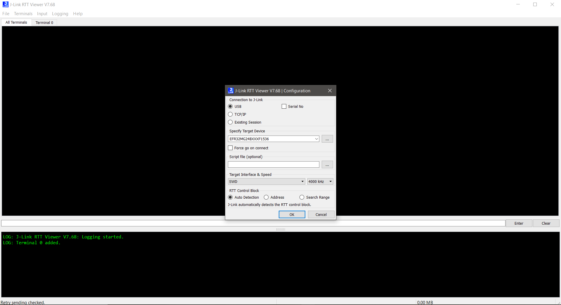
Open J-Link RTT viewer.
The device configuration dialog box is displayed.
Make sure the correct device is specified in the Specify Target Device field.
Enter the other fields as shown in the screen shot below.
Click OK.
Note: You must click File > Disconnect to close the RTT connection (if already connected) before initiating the debugging or flashing of an application.
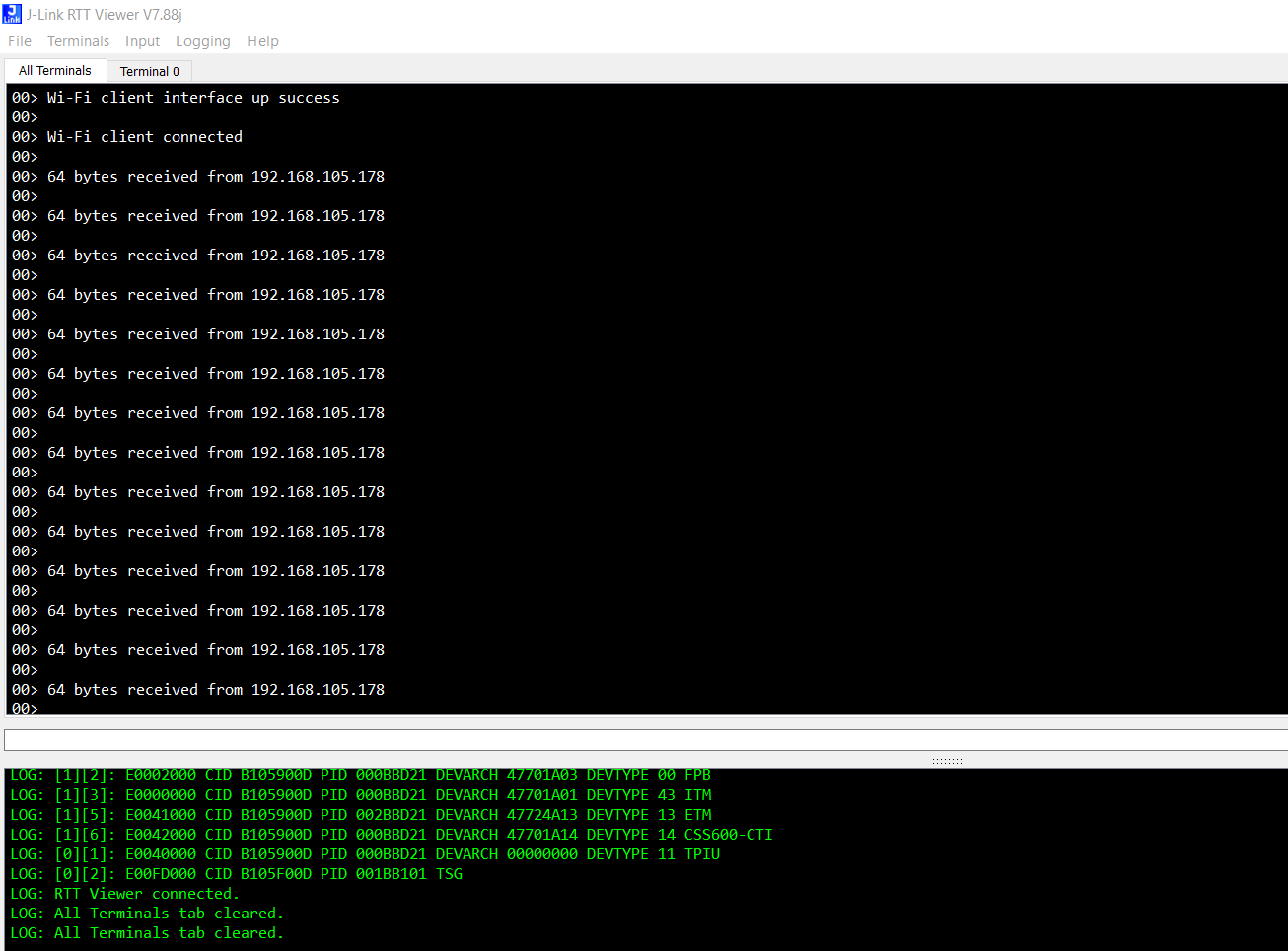
Logs will be displayed in the RTT terminal once connection is successfull.
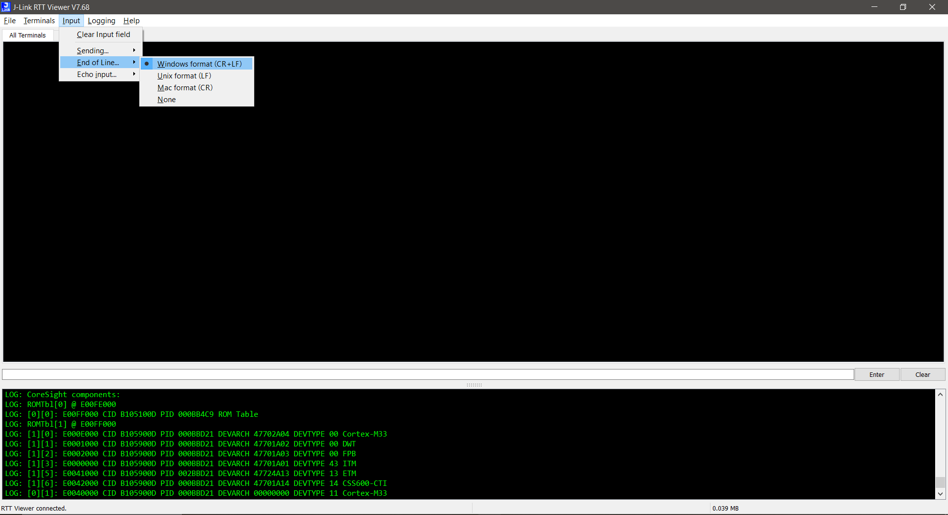
For the application which requires user input:
Select Input > End of Line... > Windows format (CR + LF) from the menu to set the end-of-line characters.
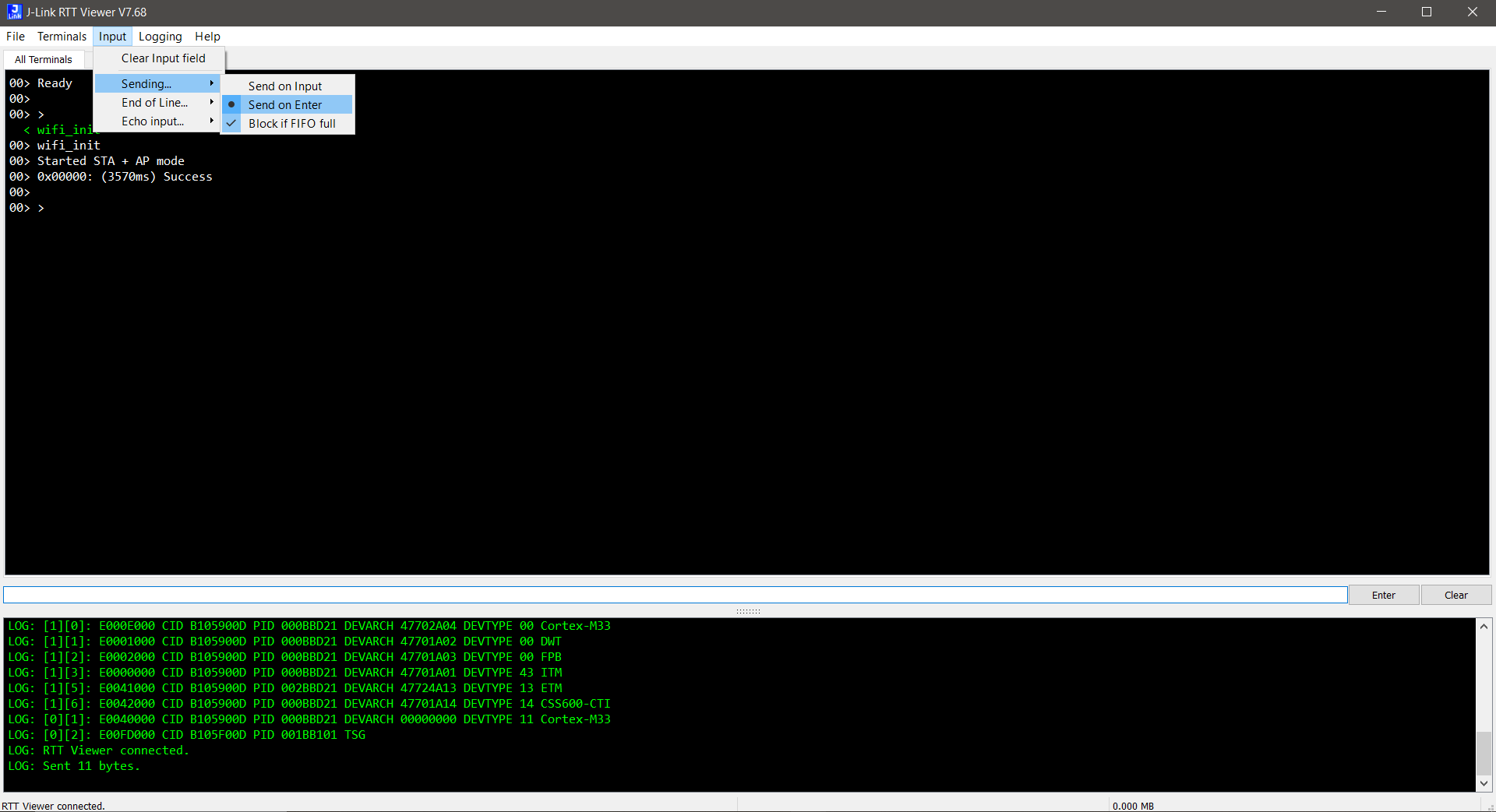
Select Input > Sending... > Send on Enter from the menu so that the entered input is sent to the EFR32 chipset when you click Enter.
To send user input, enter data in the input box below the terminal output and click Enter.
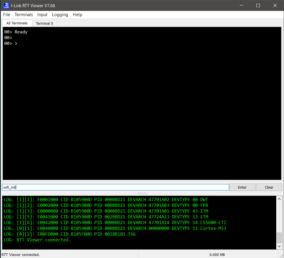
Transmitted user input is shown on the RTT terminal in green.
Flash an Application#
Note: Make sure the bootloader image is flashed separately on to the EFR32 host MCU. Refer to the Simplicity SDK (formerly Gecko SDK) Bootloading Reference for more information.
There are two alternative methods to flash an application to the application processor of the SiWx91x device:
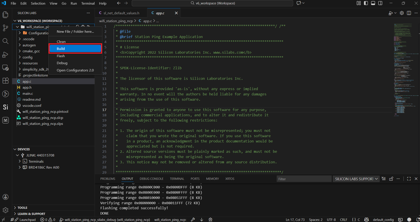
Flash an Application Built Using Simplicity Studio#
Build the application as described in the Build an Application section.
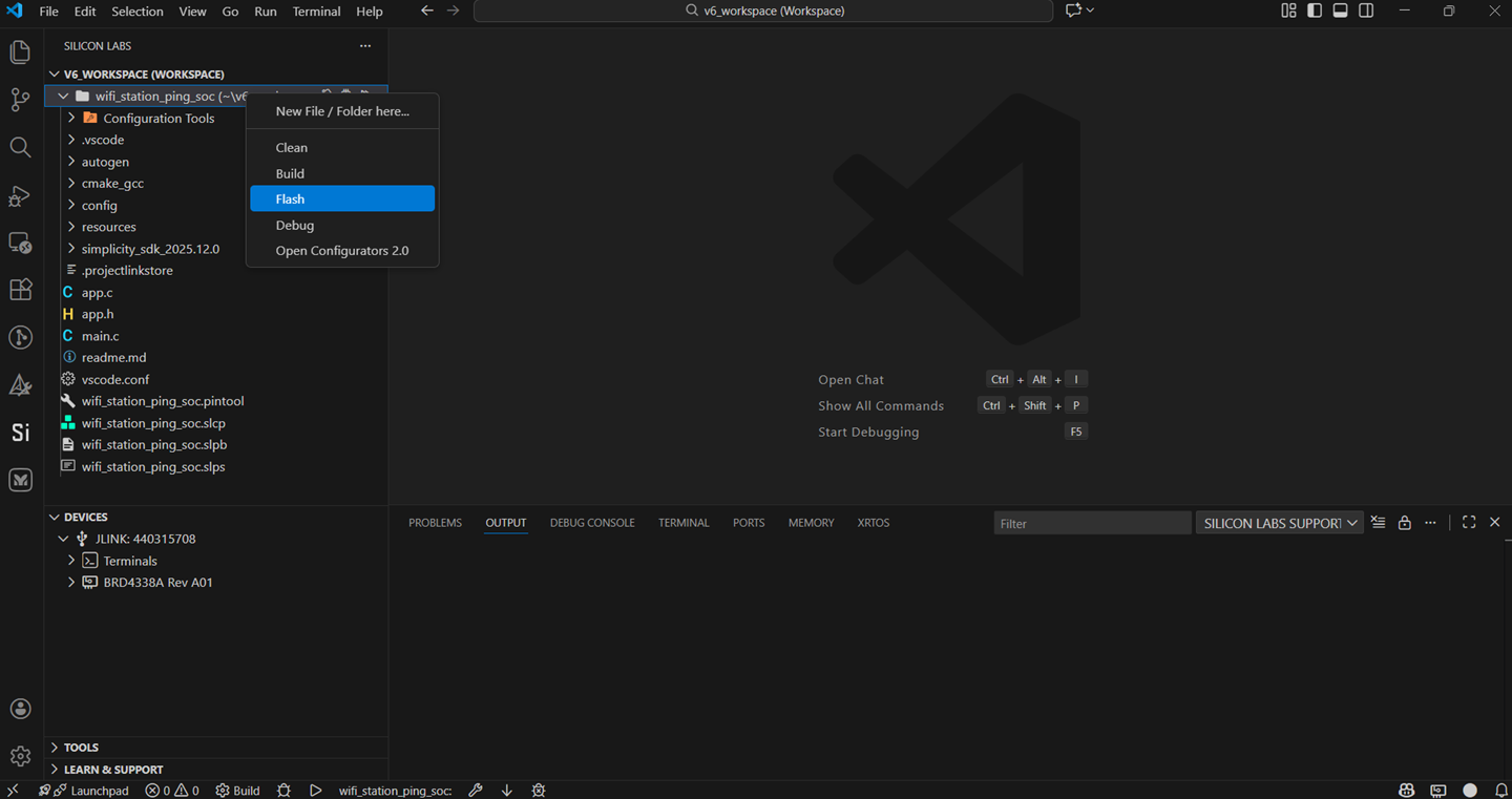
Right-click on your project name and select Flash.
Select the application binary with
.s37extension.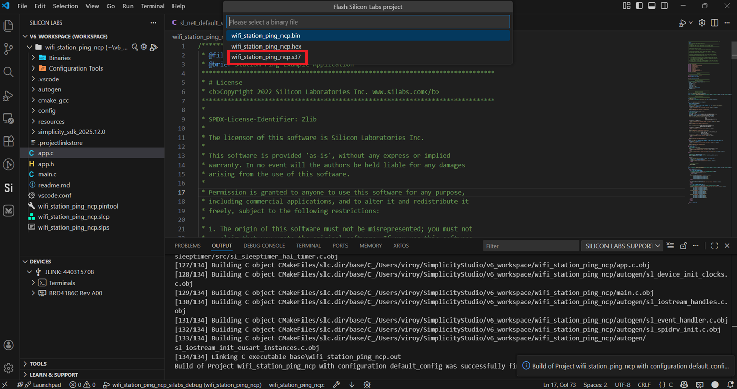
The application binary will be flashed on the EFR32 radio board and the application will start running.
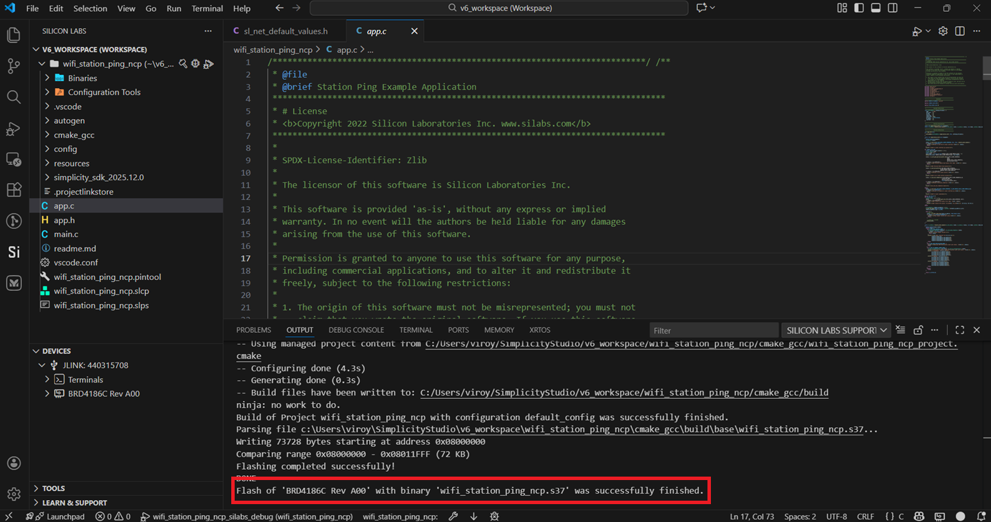
View the standard output or enter input data as needed. See the Console Input and Output section.
Note: See the troubleshooting section in case the application fails to flash.
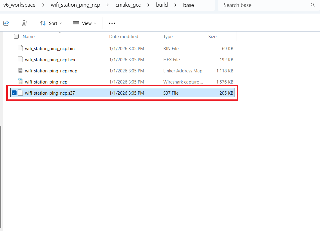
Flash the Application Binary#
If the binary was built as described in the Build an Application section, a file with a
.s37extension is generated. This file will be available under cmake_gcc > build > base in the users workspace.Alternatively, you might have obtained a
.s37file from another source, such as a binary built and provided by another user.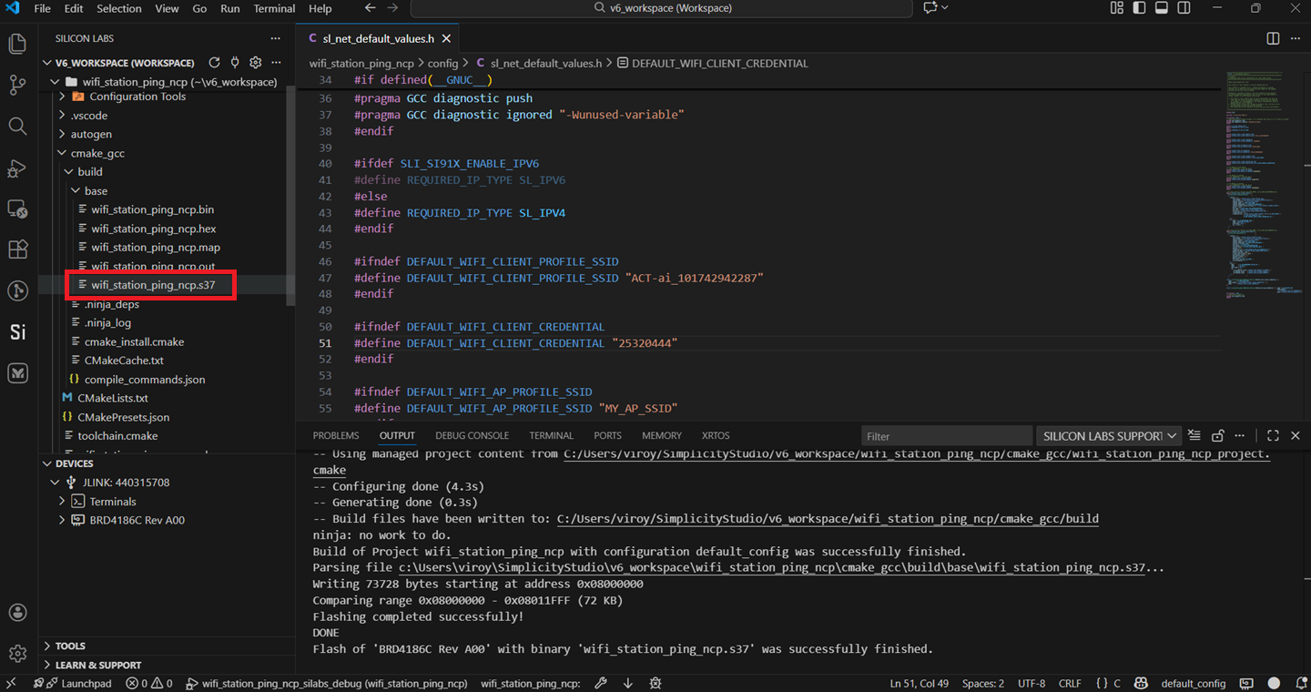
The instructions to flash the application binary are almost the same as those for flashing an SiWx91x firmware file, except for the point noted below:
Instead of choosing the SiWx91x firmware file, select the
.s37you obtained in step 1 above.
Note: If you don't see
.s37files in the sub-folder, select All files in the file filter field in the Browse dialog.
Troubleshoot an Application Flash Failure#
The application may fail to flash for one of the following reasons:
Error code 102 is displayed in the logs, indicating that ISP mode is enabled. Try the following steps:
Press and hold the ISP button on the radio board.
Press and release the RESET button on the WPK board.
Release the ISP button on the radio board.
Retry flashing the application.
"Could not connect debugger. Could not connect to target device" is displayed in the logs, indicating that the application processor is in a low power state with no flash access. Try the same steps as those described above for error 102.
Unknown reason - try re-launching Simplicity Studio.
Studio failed to detect your board. See the Troubleshoot Board Detection Failure section.
Run the Application#
Once you flash the example, you may refer to the Test the Application section of its README page to explore its output.
Note: See the Examples page to explore all available examples. To view their README pages, click on the GO to README link next to it.
Debug an Application#
See here for the instructions for debugging an application.
View the standard output or enter input data as needed. See the Console Input and Output section.
Troubleshoot an Application Debug Failure#
The application may fail to enter the debug mode due to one of the following reasons:
Studio failed to halt execution at the
main()function. Try the following steps:Click the Suspend button (having a pause button icon).
Click the Reset button (having an icon of a play button with an arrow underneath).
Retry debugging the application.
For additional tips, see the Troubleshoot an Application Flash Failure section. Follow the suggested steps and then, instead of retrying flashing the application, retry debugging the application.
Customize Application Components#
Simplicity Studio allows you to add or remove functional components in your application, such as BSD Sockets.
Note: For information about the functional components available with WiSeConnect SDK, see the Application Components section.
Add a Component#
See here for the instructions for adding a component.
Note: You may use the Component Editor to configure a component after adding it or to configure other components in your example.
Remove a Component#
See here for the instructions for removing a component.