Run Your First Z-Wave Sample Application#
This section describes how to run and test the sample application you have just configured and flashed with the help of two commonly used Z-Wave development tools: the Z-Wave PC Controller and the Z-Wave Zniffer. These come as part of the Simplicity SDK suite, described in Install the Z-Wave SDK.
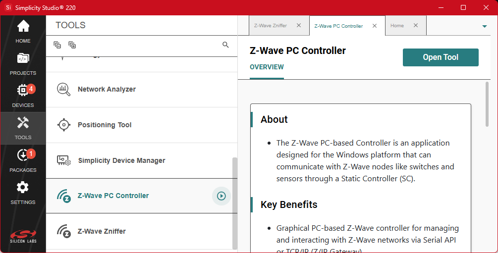
To access these tools, start by opening Simplicity Studio and navigating to the Tools page. Click on the launch icon next to the tool's name to open it.
If these tools are not already installed, you can install them using the Simplicity Installer, which can be opened by clicking the Packages button in the sidebar of Simplicity Studio. For more details, refer to the Simplicity Studio 6 User's Guide.
Z-Wave PC Controller#
The Z-Wave PC Controller is a client application for communicating with Z-Wave and Z-Wave Long Range nodes, like switches and sensors. The application requires a device running the Z-Wave Serial API Controller firmware (a compatible Radio Board or a dedicated USB stick) connected to a USB port on the PC.
The PC Controller is often used in the development of a new Z-Wave end device. The device can be included in the PC Controller’s Z-Wave network, which can then be used to test the end device by sending various commands to test the implemented functionality of the end device.
This getting started guide only covers the very basics of this tool. Refer to the manual [2] to learn about all the features of this tool.
Start by connecting the UZB Controller to your computer.
Launch the PC Controller via the Tools page in Simplicity Studio.
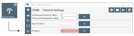
In the PC Controller dialog, click the Settings button

The PC Controller might be set to use an incompatible RF region by default. If your end device is programmed for another region, change the PC Controller's RF Region in the Transmit Settings.
Click Network Management when connection to the UZB Controller has been established.
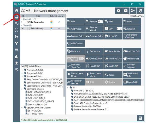
From this view you can add, remove, and send basic commands to an end device. Refer to the following sections in the PC Controller Manual [2]:
3.2 Network Management View
4.2.1 How to Add a Node
4.2.3 How to Remove a Node
To add a node, click Add and activate learn mode on your end device.
On your end device, press the button labeled BTN1 on the WSTK (for SDK versions 7.23 and above) or on the Expansion Board (for SDK versions below 7.23).
Refer to [1] for instructions on how to use the buttons.
A pop-up window will appear listing the available security classes. Click OK.
For the next step, you need the end device’s Device Specific Key or DSK. Refer to Appendix A: Reading Out QR Code and DSK for instructions on how to obtain this key.
Enter the first five digits of the DSK and click OK.
The included nodes will appear in the End Devices section with a Node ID.
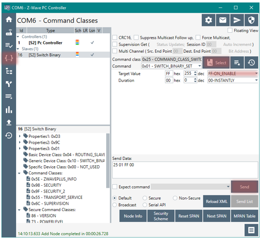
In addition to the basic functionality, it is also worth knowing from the beginning how to send various commands using the Command Class View. Refer to the Command Class View section in the PC Controller Manual [2]:
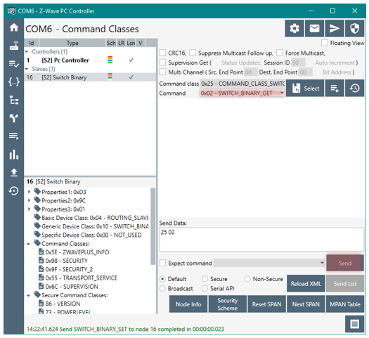
For sending a command to turn on the included switch, go to Command Classes view. Click Select and pick a supported command class, in this case ver.2–BinarySwitch » SwitchBinarySet.
Set the value and click Send. The value on the switch should now be set accordingly, which is indicated by LED0 on the WSTK (or on the EXP board for SDK versions below 7.23).
Send a Get Command to verify the switch was set accordingly.
Use Zniffer to view the response returned by the end device for the Get Command.
Z-Wave Zniffer#
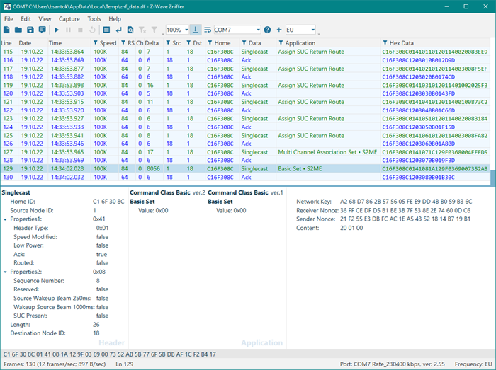
The Z-Wave Zniffer application is a development tool for capturing Z-Wave RF communication and presenting the frames in a graphical user interface on a PC.
The Zniffer tool is a passive 'listener' to the Z-Wave network traffic and will only display the RF communications taking place within direct RF range.
The tool shows the node ID of the Source and Destination for the communication, the type of frame being sent, and the application content, i.e., the specific command that is being sent.
This getting started guide will only cover the very basics of this tool. Refer to the manual [3] to learn about all the features of this tool.
Start by connecting the device running the Zniffer firmware (a compatible Radio Board or a dedicated USB stick) to your computer. For details, see Appendix B: Configuring the Development Kit as a Network Sniffer.
Launch the Zniffer via the Tools page in Simplicity Studio.
Click Detect Zniffer Modules (question mark button) in the tools bar. Then select the correct COM Port and frequency to listen in the dropdown menu.
When ready, click Start capturing frames (Play button).
From this view, you can now see the Z-Wave frames being sent/received in the network. Refer to the following sections in the Zniffer Manual [3] for a suggested next step:
4.1 Layout of the Zniffer Main Window
5 Capturing Live RF Traffic
7.5 Working with Encrypted Frames
Click Home ID to filter the trace to only show the frames of interest, in the case of multiple networks.
To decrypt a message, you must enter the Security keys, which can be found in the PC Controller under Security Settings

The initial handshake during the inclusion process must be captured in the Zniffer for it to be able to decrypt the messages.