Z-Wave Overview#
The Z-Wave protocol is a low bandwidth half duplex protocol designed for reliable wireless communication in a low-cost control network. The main purpose of the protocol is to enable short message transportation in a reliable manner. The Z-Wave protocol is not designed to transfer a large amount of data or any kind of streaming or timing critical data.
The Z-Wave Protocol Stack Architecture#
The Open System Interconnection (OSI) reference model is a representation system for characterizing and standardizing the functions of a communication system in terms of abstraction layers. This allows us to describe similar communication functionalities into logical layers. The 7 layers of the OSI model are regarded by many as an idealized model; too abstract and fine-grained for most real-world protocols. It is however useful to refer to the OSI model when describing a given communication protocol framework. With respect to that, the Z-Wave protocol stack would be described using the model as shown in the figure below. Note that the Z-Wave application layer consists of the OSI stack layers knows as transport, session, presentation, and application.
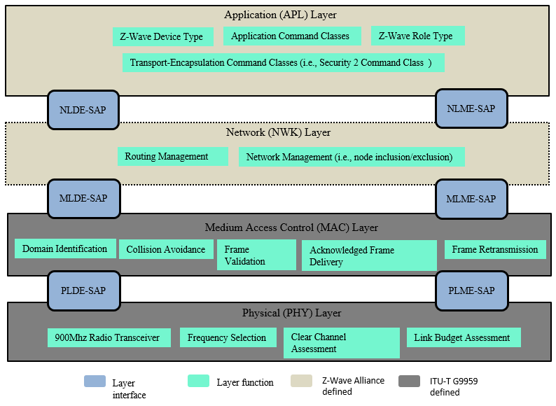
As depicted above, the Z-Wave protocol stack is made up of OSI layers where each layer performs set of services for the upper layer. Each layer has two main interfaces to facilitate the communication with upper layers through a Service Access Point (SAP). The interfaces are described as a data entity and management entity that provide a data transmission service and all other services, respectively.
ITU-T G.9959 [25] defines the physical and medium access control layers.
The physical layer offers a data flow control between the MAC and PHY layers and adds PHY-related management headers. The PHY layer is responsible for activation and deactivation of the radio transceiver, data transmission and reception, frequency selection, clear channel assessments, and the link budget assessment of received frames.
The MAC layer defines the Z-Wave data transfer model and frame structure. During a Z-Wave frame transmission, the MAC layer takes the payload data from higher layers and construct the MAC data payload (MPDU) and the MPDU header. The header comprises addresses, frame control and frame length information. The frame control field is about 16 bits in length and contains information about the frame type and other control flags that can be used by higher layer.
On the foundation of those two lower layers, the Z-Wave alliance defines the Network layer (NWK) and application layers.
The Z-Wave Network Layer (NWK) defines a multi-hop routing protocol, that is employed by Z-Wave nodes to extend their communication range. It means that the Z-Wave nodes can therefore send frames to nodes that are not in direct radio communication range. Besides, the Z-Wave NWK layer is responsible for network formation (i.e., inclusion/exclusion of nodes to/from a network) and its maintenance. The Z-Wave NWK layer manages the network establishment using command frames known as the Z-Wave Protocol Command Class (Refer to [22] in section “Command frames”). These Z-Wave NWK commands are designed for network formation specific purposes.
The Z-Wave application layer is responsible for building applications using dedicated Command Classes, (defined in [11] and [14]). To be certifiable, applications shall comply with Z-Wave device types defined in [1] and [15]. Finally, the applications layer is also responsible for providing some network management functionalities using the NWK interface (for details, refer to [2]). All the Z-Wave specifications can be found on the Z-Wave Alliance website (Member login - Select Specifications under the Home tab).
Network Layer Reference Model#
The Network Layer (NWK) provides an interface between the application layer and the MAC layer. The NWK layer relies on services provided by the MAC layer and offers services to higher layers though the Network Layer Data Entity (NLDE) and Network Layer Management Entity (NLME) service point interfaces. The NLME provides management service interface where the NWK layer management functionalities can be invoked. The NLME is responsible for maintaining a Network Information Base (NIB) that contains the routing information of the network. The figure below illustrates the components and interface of NWK layer.
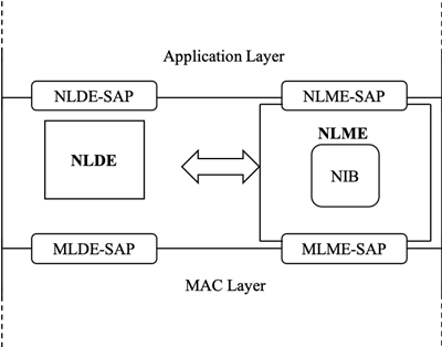
The Z-Wave NWK layer shall provide two services to the Application layer that are accessed through two SAPs:
The data service, accessed through NLDE-SAP, and
The network management service accessed through the NLME-SAP.
The detailed description of the Z-Wave NWK functional model is presented in [22], chapter “Z-WAVE NETWORK LAYER SPECIFICATION”.
Z-Wave Definitions#
Z-Wave Network Topology Basic Principles#
The following is a summary of the basic Network topology principles established by ITU-T G.9959 [25]:
Groups of nodes are divided into domains:
The division of physical nodes into domains is logical. Domains may fully or partially overlap each other’s radio frequency ranges.
The Z-Wave Network Layer supports up to 232 domains.
Each domain is identified by a unique HomeID.
Management of different domains in the same physical media is handled by individual domain masters.
The domain is a set of nodes connected to the same medium:
On node in the domain operates as a domain master, known as the Primary Controller.
Each domain may contain up to 232 nodes (including the domain master).
Each node in the domain is identified by a NodeID that is unique within the actual domain.
Nodes of the same domain can communicate with each other either directly or via other nodes in the same domain.
Nodes of different ITU-T G.9959 [25] domains:
The Z-Wave Network Layer provides connectivity within one domain. In some cases, frames from a foreign domain are repeated into the current domain.
The network is self-healing:
Nodes may autonomously establish new routes on demand. Full mesh routing is supported. There is no requirement for star or tree network topologies.
Controller and End Devices#
The Z-Wave network layer defines two networking node types: controller and end devices.
The controller nodes are responsible for setting up and maintaining the Z-Wave network. They can include or exclude nodes and they are aware for the network topology. This allows controllers to determine the possible routes between any two nodes in the network. Controllers can exchange network topology with each other.
End devices can only be added or removed from a network by a controller, they do not calculate routes, and they simply rely on route information provided by the controllers. Note that end devices can send commands to other nodes and “control” other nodes functionalities at the application level.
Both controller and end devices can participate in mesh routing. It enables nodes within a network to communicate with each other even when they are out of direct communication range.
Network Topology#
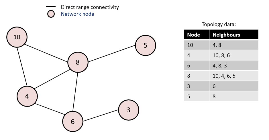
The network topology refers to the list of nodes present in a network as well the list of direct range neighbors for each node.
The figure below illustrates the concept of network topology.
Z-Wave Controller Roles#
A Z-Wave controller is a node that has the capability to provide network management functionalities such as adding/removing nodes to/from a network and distributing network topology to other controllers. The NWK layer defines several controller roles in a network:
Primary Controller#
The Primary Controller is by default the controller that starts the network. The Primary Controller can always be used to set up and maintain a network. It can add/remove nodes and knows the network topology.
There can be only one Primary Controller in a network. The Primary Controller may offer additional services to other controllers. A Primary Controller can handover the Primary Controller (and/or SUC/SIS) role to another controller.
Secondary Controller#
All controllers that are not the Primary Controller are Secondary Controllers. If the Primary Controller does not have any SUC/SIS capability, a Secondary Controller cannot include nodes, exclude nodes, or receive updated network topology automatically. If a SUC is present in the network, a Secondary Controller can request updated network topology at any time.
SUC Controller#
A Static Update Controller (SUC) is the controller that has the responsibility to keep the network topology and distribute it to other controllers, on demand. There can be only one SUC in a network. Both Primary Controllers and Secondary Controllers can be SUC.
SIS Controller#
A SUC ID Server (SIS) Controller is a controller that has both the SUC Controller role and the Primary Controller role. In addition, it provides the SIS functionality. The SIS functionality consists in the ability to reserve NodeIDs to other controllers for enabling them to include and exclude nodes.
Inclusion Controllers#
If the Primary Controller is the SIS, Secondary Controllers in the same network become Inclusion Controllers. Inclusion Controllers are secondary controllers that can include and exclude nodes on behalf of the SIS.
Node Operation Modes#
Z-Wave nodes may operate in three different receiving modes.
Always Listening (AL)#
AL node's RF receiver is always on and these nodes participate in mesh routing by repeating Routed NPDUs and Explore NPDUs. Refer to [22] in section “Routed NPDUs” and “Explore NPDUs”.
Frequently Listening (FL)#
FL nodes’ RF receiver is turned off most of the time. The RF receiver is turned on at regular intervals for a short duration to listen the Wake Up Beams. AL nodes can reach FL nodes by issuing a Wake Up Beam prior to issuing commands to the FL nodes.
FL nodes do not participate in routing and do not repeat Routed NPDUs and Explore NPDUs. Refer to [22] in section “Routed NPDUs” and “Explore NPDUs”.
ITU-T G.9959 [25] defines two possible Wake Up intervals FL nodes: 250ms and 1000ms, and three channel configurations. When operating with a channel configuration 1 and 2, some NWK commands/frames indicate which setting to use (250ms or 1000ms). When operating with channel configuration 3, the 1000ms setting is always used in frames/commands, despite using fragmented beams. For more details, refer to [25].
Non-Listening (NL)#
NL nodes cannot be awakened by another node. They wake up and transmit frames at fixed configured intervals to a single NodeID destination. NL nodes reporting can be configured using the Wake Up Command Class. For more details, refer to [12].
Network Addressing#
Z-Wave supports the following types of addressing:
Singlecast
Multicast
Broadcast
The type of addressing and its frame format are defined in the MPDU Header (refer to [25]). Broadcast may only be used in direct range. Broadcast and multicast may be used to reach more than one destination address. In case of multicast, the same payload will be delivered to selected devices only. It is mandatory that multicast always use single cast follow up to ensure devices are reached out of direct range.