Firmware Update Images and Bootloader#
This section is split into two parts: for the 700 and 800 series. Due to changes in silicon not all steps are the same between the two series. Further the guide assumes that the user is running the latest version of Simplicity Studio (which at the time of writing the guide is V5).
Detailed information regarding bootloaders for the 700 and 800 series is available in Bootloader Fundamentals.
Silicon Labs Gecko Bootloader User’s Guide for GSDK 4.0 and Higher.
Before going further into this guide, it is important to know a few files and locations that are crucial in following the subsequent steps.
Default Simplicity Studio Installation Location: C:\SiliconLabs\SimplicityStudio\v5
Default SDK Installation Location: C:\Users{Username}\SimplicityStudio\SDKs
Default Workspace Location: C:\Users{Username}\SimplicityStudio\v5_workspace
Sample encryption keys: (sample_sign.key, sample_sign.key.pub, sample_sign.key-tokens.txt, sample_encrypt.key)
OTA gbl file 255 version: for purposes of this exercise, let it be the SwitchOnOff file. (SwitchOnOff_brd4204d_REGION_EU_v255.gbl). Sample gbl files are located in {SDK Installation Location}\gecko_sdk_4.1.0\protocol\z-wave\Apps\bin\gbl
Bootloader image files: ota-EFR32ZG23_BRD4204D-crc.s37
sample keys location: {SDK Installation Location}\gecko_sdk\protocol\z-wave\BootLoader\sample-keys
bootloader location: {Simplicity Studio Installation Location}\offline\com.silabs.sdk.stack.super_4.0.1\protocol\z-wave\Apps\bin
Commander utility location: {Simplicity Studio Installation Location}\developer\adapter_packs\commander
Sample project location : {Default Workspace Location}\SwitchOnOff\GNU ARM v10.2.1 – Default
Note: The above paths are customizable by the user and as such must be adapted if they are different from the default paths given above.
For the 700 series#
The purpose of this section is to describe how to generate and manage firmware update images. The SDK provides two bootloaders for a given board type – OTA and OTW. The OTA bootloader is needed for all ZW700 based devices, which implement firmware updates; the OTW bootloader is for devices, which update firmware using the serial port from another host controller. The OTA bootloader is triggered when an image has been transferred over the air using the FIRMWARE_UPDATE command class. The transferred image must be an image in Gecko Bootloader(GBL) format. The bootloaders provided in the SDK require the GBL image to be signed.
Three steps are needed for performing an OTA update:
The OTA bootloader must be flashed.
The Signing keys and optionally an encryption key must be flashed.
A signed image must be transferred using the firmware update command class.
The OTA key locations are as follows depending on SoC:
For ZGM13: protocol\z-wave\BootLoader\sample-keys
For EFR32ZG14P: protocol\z-wave\BootLoader\ZG14_keys
Further information about the bootloaders can be found in [17].
Generate GBL Files
To generate the GBL files needed for the OTA update, a signing keypair must first be created. It is the intention that a vendor will keep the signing keypair for the lifetime of the product. These keys are used to sign all firmware versions for the whole lifetime of the product. An encryption key must also be created, this key is intended for encrypting the GBL file. Encryption makes it harder for a bootlegger to copy the product.
The signing keys can be created by using Simplicity Commanders command line interface.
commander.exe gbl keygen --type ecc-p256 -o vendor_sign.key
This step will create 3 files:
vendor_sign.key - This is the private key and must be kept safely by the product manufacturer.
vendor_sign.key.pub - This is the public key.
vendor_sign.key-tokens.txt - This is the public key in another format which can be programmed into the device at manufacturing using simplicity commander.
A vendor may choose to have a key pair like this for all his products, or one for each product type.
An encryption key can be generated as follows:
commander.exe gbl keygen --type aes-ccm -o vendor_encrypt.key
Once the two keys have been obtained, a GBL file may be produced as follows:
commander.exe gbl create appname.gbl --app appname.hex --sign vendor_sign.key --encrypt vendor_encrypt.key --compress lz4
This should be done each time a new firmware is produced.
Flashing the Bootloader and App
It is possible to flash the bootloader including the public signing key and the encryption key using commander.exe. The list below shows args to commander.exe for a board having SN 440049475 as an example:
Erase Flash args:device masserase -s 440049475 -d Cortex-M4
Reset args:device reset -s 440049475 -d Cortex-M4
Erase Bootloader args:device pageerase --region @bootloader -s 440049475 -d Cortex-M4
Erase Lockbits args:device pageerase --region @lockbits -s 440049475 -d Cortex-M4
Program Bootloader args:flash C:\dk2\Apps458\BootLoader_7.11.0_458\OTA-bootloader-fg13-combined.s37 -s 440049475 -d Cortex-M4
Program Keys args:flash --tokengroup znet --tokenfile C:\dk2\Apps458\BootLoader_7.11.0_458\sample_encrypt.key --tokenfile C:\dk2\Apps458\BootLoader_7.11.0_458\sample_sign.key-tokens.txt -s 440049475 -d Cortex-M4
Erase Flash args:device masserase -s 440049475 -d Cortex-M4
Reset args:device reset -s 440049475 -d Cortex-M4
Program Flash args:flash "C:\dk2\Apps458\PowerStrip\ZW_PowerStrip_7.11.0_458_ZGM130S_REGION_IN.hex" --address 0x0 --serialno 440049475 --device Cortex-M4
Reset args:device reset -s 440049475 -d Cortex-M4
Minor modifications are needed in steps 3 and 4 if the commands are run on a Windows Powershell:
Erase Bootloader args:device pageerase --region "@bootloader" -s 440049475 -d Cortex-M4
Erase Lockbits args:device pageerase --region "@lockbits" -s 440049475 -d Cortex-M4
Note that the bootloader and keys are not erased by a normal mass erase.
For the 800 series#
800 series is different from the 700 series. The process for preparing the eval board to test OTA is easier on the 800 series.
Download the bootloader image files. This is done by running the sample demo in Simplicity Studio. This will download the bootloader images to disk.
Create an example project using the same project above as a template.
Build the project in SimplicityStudio and generate the hex files.
Erase device
commander.exe device masserase -s {jlink_serial}Reset device
commander.exe device reset -s {jlink_serial}Flash the appropriate OTA bootloader image – for purposes of this exercise, let it be eval board BRD4204.
commander.exe flash {bootloader location}\ota-EFR32ZG23_BRD4204D-crc.s37 -s {jlink_serial}Flash initial device firmware built in step 3
commander.exe flash "{sample project location}\SwitchOnOff.hex" --address 0x0 -s {jlink_serial}Flash the encryption keys.
commander.exe flash --tokengroup znet --tokenfile sample_encrypt.key --tokenfile sample_sign.key-tokens.txt -s {jlink_serial}Reset device
commander.exe device reset -s {jlink_serial}Connect a controller or a device running a controller firmware to the PC and start the PC controller application.
Include the node into the network and make sure the device is visible.
In the PC controller application initiate the OTA update using the OTA gbl file mentioned in the prerequisites.
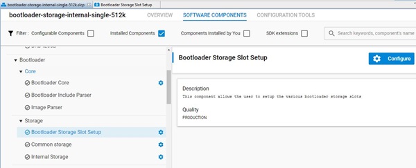
Notes on Bootloader configuration for the 800 series
The bootloader resides at the start address 0x08000000 of the main flash and a fixed space of 24KB is reserved for this. Z-Wave applications will start from address 0x08006000.
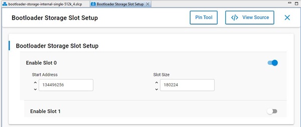
The bootloader must be flashed first before the Z-Wave sample application is flashed. It is also possible to combine the bootloader and the Z-Wave application into a single image. One can use the pre-built bootloader images available in Simplicity Studio or build a bootloader image by themselves using the bootloader sample applications in Simplicity Studio. When building the bootloader, the OTA image storage information must be configured as shown in the following screenshots. Importantly, this storage slot (slot0), start address and size must not be changed.
The postbuild.sh script available in the Simplicity Studio project for Z-Wave sample applications can be used as an example to combine the bootloader and the Z-Wave application into a single image. This script also contains reference example for generating the OTA images.
Linker script for 800 series
The Z-Wave sample applications that are available in Simplicity Studio contain linker scripts that have been tuned to accommodate the OTA image related configuration also. It is a recommendation to not modify this linker script when developing applications.
Bootloader compression for 800 series
The bootloader compression type used for OTA is lzma compression. The corresponding component name to be selected in studio is bootloader_compression_lzma.
Application upgrade version
The studio component bootloader_app_upgrade_version has to be selected for checking the application version during upgrades.
Building a Custom Bootloader#
The bootloader provided with the SDK is built for using the internal flash for storing the downloaded OTA image. This design ensures the lowest possible HW cost of a product but also reduce the code space available for the application. In some products it might be desirable to have more code space and that can be achieved by having the OTA image in an external Flash. If this option is used, an alternative bootloader must be built and programmed onto the product.
The steps to use external flash are:
Use simplicity Studio to create a OTA bootloader for the external Flash you want to use. For details about how to configure the bootloader see [27]
Make sure that the configuration fits the configuration in
protocol\z-wave\ZAF\CommandClasses\FirmwareUpdate\ota_util.c.
Modify linker script.
Copy the default linker script in
protocol/z-wave/Z-Wave/linkerscripts/zgm13-zw700.ldto your local application project and set studio up to use that file for linking in Properties -> C/C++ Build -> Settings -> Memory Layout.
Edit the new linker file.
Extend the FLASH section in the linker script from 232K up to a maximum of 264K to get more code space for the application.
Compile the application.
Remember to follow the steps in the previous chapters to generate a valid firmware update file.
Erase and Read MFG Frequency#
There is a dedicated space in the flash memory where the Manufacturing Tokens datas can be stored. This area can be write once during firmware running. To save the new region the flash must be erased before.
Read token frequency: commander tokendump --tokengroup znet --token MFG_ZWAVE_COUNTRY_FREQ
Write token frequency: commander flash --tokengroup znet --token MFG_ZWAVE_COUNTRY_FREQ:0xFF
0xFF mean, this area is erased.