Z-Wave Long Range Protocol Overview#
The Z-Wave Long Range Protocol Stack Architecture#
The Z-Wave Long Range protocol stack is similar to the Z-Wave protocol stack as illustrated below.
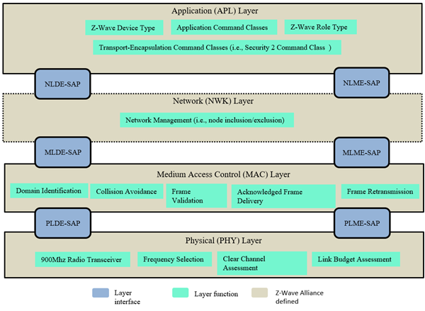
Each layer has two main interfaces to facilitate the communication with upper layers through an SAP. The interfaces are described as a data entity and management entity that provide a data transmission service and all other services, respectively.
“Z-Wave Long Range PHY layer specifications” [23] defines the physical layer and “Z-Wave Long Range MAC layer specifications” [24] defines the medium access control layer.
On the foundation of those two lower layers, the Z-Wave alliance defines the Network layer (NWK) and application layers.
The Z-Wave Long Range NWK layer is responsible for network formation (i.e., inclusion/exclusion of nodes to/from a network). The Z-Wave Long Range NWK layer manages the network establishment using command frames known as the Z-Wave Long Range Command Class (refer to [22] in section “Command frames”). These NWK commands are designed for network formation specific purposes.
The Z-Wave application layer is responsible for building applications using dedicated Command Classes, (defined in [11] [14]). To be certifiable, applications shall comply with Z-Wave device types defined in [1] and [15]. Finally, the applications layer is also responsible for providing some network management functionalities using the NWK interface (for details, refer to [2]).
Z-Wave Long Range Network Layer Reference Model#
The Z-Wave Long Range NWK layer provides an interface between the application layer and the MAC layer. The Z-Wave Long Range NWK layer relies on services provided by the MAC layer and offers services to higher layers though the Network Layer Data Entity (NLDE) and Network Layer Management Entity (NLME) service point interfaces. The Network Layer Reference Model illustrates the components and interface of the Z-Wave Long Range NWK layer.
The Z-Wave Long Range NWK layer shall provide two services to the Application layer that are accessed through two SAPs:
The data service, accessed through NLDE-SAP
The network management service accessed through the NLME-SAP
For a detailed description of the Z-Wave Long Range NWK functional model, refer to [22] in section “Z-WAVE LONG RANGE NETWORK LAYER SPECIFICATION”.
Z-Wave Long Range Definitions#
Z-Wave Long Range Network Principles#
The following is a summary of the network principles established by [23] and [24]:
Groups of nodes are divided into domains:
The division of physical nodes into domains is logical. Domains may fully or partially overlap each other’s radio frequency ranges.
The Z-Wave Network Layer supports up to 232 domains.
Each domain is identified by a unique HomeID.
The domain is a set of nodes connected to the same medium:
Each domain may contain up to 4000 nodes.
Each node in the domain is identified by a NodeID that is unique within the actual domain.
Nodes of the same domain can only communicate with the controller using direct range transmissions.
Controller and End Devices#
Refer to Z-Wave Controller Roles.
Network Topology#
Refer to Network Topology.
Nodes added to a network using Z-Wave Long Range will only have one known neighbor, which is the Primary Controller.
Z-Wave Controller Roles#
Refer to Z-Wave Controller Roles.
A controller starting a Z-Wave Long Range network shall assume the Primary controller role.
The SUC/SIS functionalities will not be used in a Z-Wave Long Range network and included controllers will be Secondary Controllers.
Node Operation Modes#
Refer to Node Operation Modes.
Network Addressing#
Z-Wave Long Range supports the following type of addressing:
Singlecast
Broadcast
The type of addressing and its frame format are defined in the MPDU Header. Refer to [24].