TrustZone Basics#
Introduction#
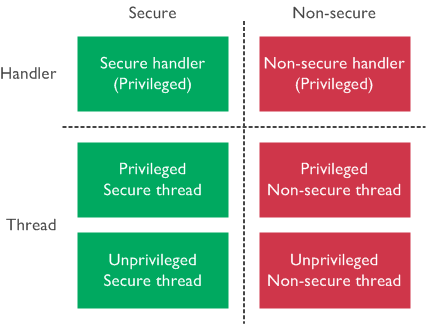
TrustZone for ARMv8-M adds extra states to the Cortex-M processor operations to ensure there is a Secure and Non-secure state. These security states are orthogonal to the existing Thread and Handler modes, thereby having both a Thread and Handler mode in both Secure and Non-secure states. The Thread mode can also be either Privileged or Unprivileged.
Copyright © 1995-2022 Arm Limited (or its affiliates). All rights reserved.
TrustZone for ARMv8-M is an optional architecture extension. By default, the system starts up in a Secure state if the processor implements the TrustZone security extension. The division of Secure and Non-secure worlds is memory-map based (security state depends on the address of the fetched instruction), and the transitions happen automatically. It is also possible to leave the Non-secure state unused and execute the whole application in the Secure state.
Memory Security Attributes#
TrustZone classifies memory into four security attributes as described in the following table.
Security Attribute | Processor State | Description |
|---|---|---|
Non-secure (NS) | Non-secure | Non-secure and Secure software can access these memory regions. |
Secure (S) | Secure | Secure software can access these memory regions. Non-secure software cannot gain access to the Secure memory. |
Non-secure Callable (NSC) | Secure | Secure memory with an NSC attribute provides entry points for Secure APIs that can be called from a Non-secure space. It is a region of memory that contains the Secure Gateway (SG) veneers that allow Non-secure code to call secure functions that exist in Secure code. Non-secure software cannot read/write to an NSC memory but can branch into it if the branch target is an SG instruction. |
Exempted | Secure/Non-secure | Non-secure and Secure software can access these memory regions (exempted from security checking). Exempted regions are typically used by debugging components that do not pose any security risk (e.g., system ROM table) when accessed by the Non-secure software. |
Note: The Non-secure Callable is also known as Secure Non-secure Callable (Secure NSC) to declare that this region resides in Secure memory.
Banked Register#
The concept of a banked register in ARMv8-M between Secure and Non-secure states means that there are two copies of the register, and the core automatically uses the copy that belongs to the current security state. When a register is banked, the _S and _NS suffixes are used in the ARMv8-M architecture to identify whether the resource is for the Secure state or Non-secure state.
General-Purpose Registers#
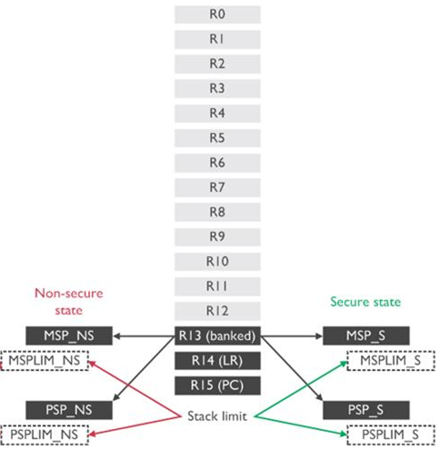
The Cortex-M processors have 16 general-purpose registers (R0 - R15) for data processing (R0 - R12) and control. The following figure shows the general-purpose register view of the ARMv8-M system with TrustZone. Refer to the ARM Cortex-M33 Devices Generic User Guide for details about these registers.
Copyright © 1995-2022 Arm Limited (or its affiliates). All rights reserved.
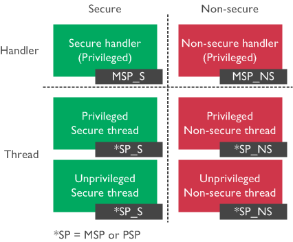
The Secure or Non-secure state can access the data processing registers R0 - R12 and special usage registers R13 - R15. The register R13 (banked SP) is the stack pointer alias, and the actual stack pointer (MSP_NS, PSP_NS, MSP_S, PSP_S) accessed depends on the state (Secure or Non-secure) and mode (Handler or Thread) as described in the following figure.
In addition, stack limit registers (special registers) enable hardware to detect stack overflow conditions. Two pairs of stack limit registers (MSPLIM_NS and PSPLIM_NS, MSPLIM_S and PSPLIM_S) are implemented, one per security state, to protect the Main Stack Pointer (MSP) and Process Stack Pointer (PSP).
Copyright © 1995-2022 Arm Limited (or its affiliates). All rights reserved.
In Thread mode, execution can be privileged or unprivileged. The stack pointer used can be the MSP or PSP, depending on the SPSEL bit in the CONTROL register. When in Handler mode, the processor is Privileged. The stack pointer is always MSP.
It is possible to directly access the stack pointers (MSP and PSP) and stack limit registers (MSPLIM and PSPLIM), providing that the processor is in a privileged state. If the processor is in a Secure privileged state, the software can also access the Non-secure stack pointers (MSP_NS and PSP_NS) through Core Register Access Functions in CMSIS-Core.
Special-Purpose Registers#
Except for the general-purpose registers, there are several special-purpose registers for conditional flags, interrupt masking, control, and stack pointer limit. The following figure shows the special-purpose registers view of the ARMv8-M system with TrustZone. Refer to the ARM Cortex-M33 Devices Generic User Guide for details about these registers.
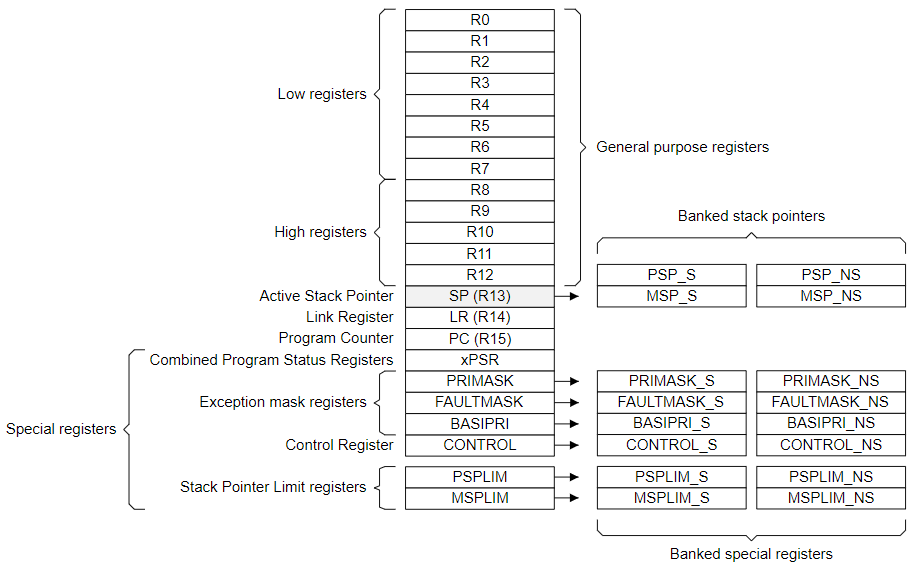
Image:https://documentation-service.arm.com/.Copyright © 1995-2022 Arm Limited (or its affiliates). All rights reserved.
The Combined Program Status Register (xPSR) consists of the Application Program Status Register (APSR), Interrupt Program Status Register (IPSR), and Execution Program Status Register (EPSR).
Some of the special-purpose registers are banked between Secure and Non-secure states. Special-purpose registers are not memory-mapped and can be accessed using Core Register Access Functions in CMSIS-Core (except for EPSR in xPSR).
Secure privileged software can also access the Non-secure interrupt masking registers (PRIMASK_NS, FAULTMASK_NS, and BASEPRI_NS), CONTROL register (CONTROL_NS), and stack limit registers (MSPLIM_NS and PSPLIM_NS) through Core Register Access Functions in CMSIS-Core.
System Private Peripheral Bus (PPB)#
The banking of registers is usually used to separate the Secure and Non-secure information of the system components inside the processor. The following figure shows the System Private Peripheral Bus (PPB) registers view of the ARMv8-M system with TrustZone. Refer to the ARM Cortex-M33 Devices Generic User Guide for details about the System PPB registers.
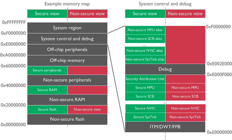
System components for debugging and trace operations (0xE0000000 to 0xE0002FFF):
Instrumentation Trace Macrocell (ITM)
Data Watch point and Trace unit (DWT)
Flash Patch and Breakpoint unit (FPB)
System Control Space (SCS):
The registers in SCS address spaces are memory-mapped and can be accessed using pointers in software
Secure SCS (
0xE000E000to0xE000EFFF) - Secure software using this address space to access the banked Secure SCS registers (e.g.,SCB->CPUID)Non-secure SCS (
0xE000E000to0xE000EFFF) - Non-secure software using this address space to access the banked Non-secure SCS registers (e.g.,SCB->CPUID)Non-secure alias SCS (
0xE002E000to0xE002EFFF) - Secure software using this address space to access the Non-secure SCS registers (e.g.,SCB_NS->CPUID)
The following table describes some core peripherals in the SCS and corresponding data structures defined in the CMSIS-Core header file to access the registers of core peripherals in two SCS address spaces.
Core Peripheral | Data Structure for Secure and NS SCS | Data Structure for NS Alias SCS |
|---|---|---|
Implementation Control Block | SCnSCB (0xE000E004) | SCnSCB_NS (0xE002E004) |
SysTick Timer | SysTick (0xE000E010) | SysTick_NS (0xE002E010) |
Nested Vectored Interrupt Controller | NVIC (0xE000E100) | NVIC_NS (0xE002E100) |
System Control Block | SCB (0xE000ECFC) | SCB_NS (0xE002ECFC) |
Memory Protection Unit | MPU (0xE000ED90) | MPU_NS (0xE002ED90) |
Security Attribution Unit | SAU (0xE000EDD0) | - |
Debug Control Block | CoreDebug (0xE000EDF0) | CoreDebug_NS (0xE002EDF0) |
Software Interrupt Generation | STIR (0xE000EF00) | STIR_NS (0xE002EF00) |
Floating-Point Extension | FPU (0xE000EF34) | FPU_NS (0xE002EF34) |
Notes:
The SCB is a group of system control registers for the various usages below.
System Control Register (SCR) to configure processor low power mode
Fault Status Register (xFSR) to provide fault status information
Vector Table Offset Register (VTOR) for vector table relocation
The SAU register is accessible from the Secure state only.
The STIR register is not physically banked.
Core peripherals such as SysTick, SCB, and MPU are duplicated. One instance is Secure and the other one is Non-secure.
Secure software can use the corresponding functions for ARMv8-M in CMSIS-Core to configure the Non-secure NVIC and SysTick through the Non-secure alias SCS.
Debug or vendor specific components (0xE0040000 to 0xE00FFFFF):
Optional debug components (e.g., ETM)
External Private Peripheral Bus (EPPB) allows designers to add their own debug or vendor-specific components
System ROM Table is a simple lookup table that enables debug tools to extract the addresses of debug and trace components
Secure Attribution Unit (SAU), Implementation Defined Attribution Unit (IDAU), and Memory Protection Unit (MPU)#
Two units determine the security attribute of an address:
The internal programmable Secure Attribution Unit (SAU).
The external Implementation Defined Attribution Unit (IDAU), through the IDAU interface, returns the security attribute and region number of an address.
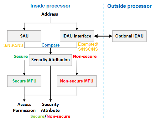
Three possible configurations to define the security attribute of an address:
Internal SAU only
External IDAU only
A combination of the internal SAU and external IDAU
Notes:
Series 2 devices use configuration 3.
IDAU in Series 2 devices is the External Secure Attribution Unit (ESAU).
The Memory Protection Unit (MPU) is a programmable unit that allows privileged software to define memory access permission. If the TrustZone is enabled, there can be up to two MPUs, one for Secure and one for Non-secure.
The number of MPU regions for the Secure and the Non-secure MPU can be different.
The MPU registers are memory-mapped and are placed in the System Control Space (SCS).
Secure software can use the MPU Functions for ARMv8-M in CMSIS-Core to configure the Non-secure MPU through the Non-secure alias SCS (
0xE002ED90-0xE002EDC4).
| Software | Non-secure MPU Registers | Secure MPU Registers | MemManage Fault |
|---|---|---|---|
Non-secure privileged | 0xE000ED90 - 0xE000EDC4 | - | Non-secure MPU violation |
Secure privileged | 0xE002ED90 - 0xE002EDC4 | 0xE000ED90 - 0xE000EDC4 | Secure MPU violation |
Exceptions and Interrupts#
Type of Exceptions#
The following table describes the types of exceptions in the TrustZone implemented system.
| Section | Guidance | Type | Default State |
|---|---|---|---|
1 (-) | Reset | Secure only | Secure |
2 (-14) | NMI | Configurable | Secure |
3 (-13) | HardFault | Configurable | Secure |
4 (-12) | MemManage Fault | Banked | Banked |
5 (-11) | BusFault | Configurable | Secure |
6 (-10) | UsageFault | Banked | Banked |
7 (-9) | SecureFault | Secure only | Secure |
11 (-5) | SVCall | Banked | Banked |
12 (-4) | DebugMonitor | Configurable | Secure |
14 (-2) | PendSV | Banked | Banked |
15 (-1) | SysTick | Banked | Banked |
16 - 495 (0 - 479) | IRQ0 - IRQ479 | Configurable | Secure |
Notes:
"Secure only" means the system exceptions can only trigger in the Secure state.
"Configurable" means the system exceptions and interrupts can be configured to target either the Secure state or the Non-secure state.
Banked means the system exceptions can have Secure and Non-secure versions. Both can be triggered and executed independently and have different priority level settings.
Exception Priorities#
It may cause a security issue if the Non-secure software uses high priority levels to mask the Secure interrupts. To avoid this issue, TrustZone introduces a programmable bit in the AIRCR register called PRIS (Prioritize Secure exception) for Secure software to prioritize, if needed, Secure exceptions and interrupts.
The AIRCR.PRIS is set to 0 out of reset, which means Secure and Non-secure exceptions/interrupts share the same configurable programmable priority level space (columns 2 and 3 in the following table). When the AIRCR.PRIS is set to 1, all Non-secure configurable exceptions/interrupts are placed in the lower half of the priority level space so that Secure exceptions/interrupts can potentially have higher priorities (columns 2 and 4 in the following table).
| Priority Value | Secure Priority | Non-secure Priority (PRIS = 0) | Non-secure Priority (PRIS = 1) |
|---|---|---|---|
0 | 0 | 0 (0x00) | 128 (0x80) |
1 | 32 | 32 (0x20) | 144 (0x90) |
2 | 64 | 64 (0x40) | 160 (0xA0) |
3 | 96 | 96 (0x60) | 176 (0xB0) |
4 | 128 | 128 (0x80) | 192 (0xC0) |
5 | 160 | 160 (0xA0) | 208 (0xD0) |
6 | 192 | 192 (0xC0) | 224 (0xE0) |
7 | 224 | 224 (0xE0) | 240 (0xF0) |
Note: This table uses three bits (Bit [7:5]) of the group priority level (
AIRCR.PRIGROUP) to limit the maximum number of preemption levels to 8. A lower priority value indicates a higher priority.
Vector Tables#
The following figure shows two vector tables for Secure and Non-secure exceptions and interrupts. The vector table offset is defined by a Vector Table Offset Register (VTOR at 0xE000ED08), which can only be programmed in the privileged state.
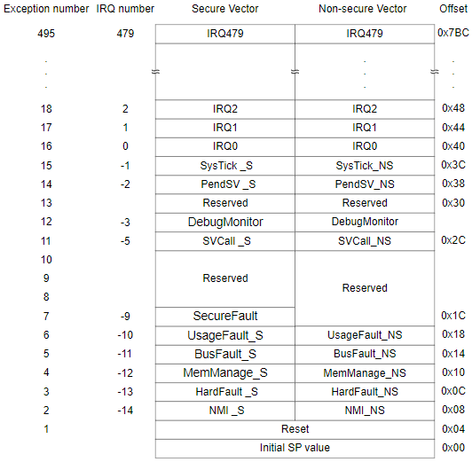
Image: Vector Table.Copyright © 1995-2022 Arm Limited (or its affiliates). All rights reserved.
Notes:
The
VTOR_Sdefines the address of the Secure vector table in Secure memory, and the Secure Main Stack Pointer (MSP_S) is the default stack for the Secure exception handler.The
VTOR_NSdefines the address of the Non-secure vector table in Non-secure memory, and the Non-secure Main Stack Pointer (MSP_NS) is the default stack for the Non-secure exception handler.Secure privileged software can access the
VTOR_NSusing the Non-secure SCB alias (0xE002ED08).The System Control Space contains registers for the SysTick timer, NVIC, and SCB.
The interrupt masking registers (PRIMASK, FAULTMASK, and BASEPRI) are banked between security states. The priority level space is shared between the Secure and the Non-secure world, setting an interrupt mask register on one side can block some, or all, of the exceptions on the other side.
Interrupts (
IRQ0-IRQ479) are defined as Secure by default. Each interrupt can be configured as Secure or Non-secure and is determined by the Interrupt Target Non-secure (NVIC_ITNS) register, which is only programmable in the Secure software.
State Transitions in Exceptions and Interrupts#
The following figure shows transitions between the processor states in ARMv8-M TrustZone.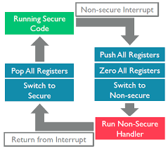
Image (left): Switching-between-Secure-and-Non-secure-states.Copyright © 1995-2022 Arm Limited (or its affiliates). All rights reserved.
Secure Thread → Secure Handler or Non-secure Thread to Non-secure Handler
No security state transition.
The exception sequence is almost identical to the exception stacking mechanism of current Cortex-M processors.
The Interrupt Service Routine (ISR) is executed in the current security state (either Secure or Non-secure).
Non-secure Thread → Secure Handler or Non-secure Handler → Secure Handler
The transition from Non-secure to Secure state.
The exception sequence is almost identical to the exception stacking mechanism of current Cortex-M processors.
The ISR is executed in a Secure state.
Secure Thread → Non-secure Handler or Secure Handler → Non-secure Handler
The transition from Secure to Non-secure state.
To avoid an information leak when transitioning from the Secure to Non-secure state. The processor automatically pushes all general-purpose registers into the Secure stack and erases the contents of all general-purpose registers before executing the Non-secure ISR. The processor pops the contents of all general-purpose registers from the Secure stack when returning from the Non-secure ISR (right side in Figure 2.6 State Transitions on page 12). It incurs a slightly longer interrupt latency.
The ISR is executed in a Non-secure state.
Secure Privileged Thread ↔ Non-secure Privileged Thread or Secure Unprivileged Thread ↔ Non-secure Unprivileged Thread
The transition from Secure to Non-secure state or Non-secure to Secure state.
The Function calls and returns can be used when the privileged level remains the same.
Note: Subject to interrupt priority, there are no restrictions regarding whether a Non-secure or Secure interrupt can occur when the processor runs Non-secure or Secure code.
Switching Between Secure and Non-secure States#
The TrustZone allows direct calling between Secure and Non-secure software. The following figure shows how to use an API function call to trigger security state transitions. The state transitions can also happen because of exceptions and interrupts.

Image: Switching-between-Secure-and-Non-secure-states.Copyright © 1995-2022 Arm Limited (or its affiliates). All rights reserved.
Switching from Non-secure to Secure State#
When the Non-secure program calls a Secure software, the first instruction must be a Secure Gateway (SG) instruction residing in Non-secure Callable memory. The Secure Gateway entry points (veneers) decouple the address of the SG instructions in the Non-secure Callable memory region from the rest of the Secure code. It can eliminate the risk of having inadvertent entry points when the Secure software contains a pattern that matches the opcode of the SG instruction.
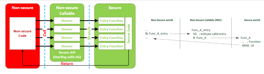
Image (right): Whitepaper - ARMv8-M Architecture Technical Overview. Copyright © 1995-2022 Arm Limited (or its affiliates). All rights reserved.
The bit 0 of the Link Register (LR) is cleared to zero by SG instruction to indicate that returning from this function transits from Secure to Non-secure. The processor is still in the Non-secure state when the SG instruction is executed. The BXNS LR instruction is used when returning since a normal BX LR instruction interprets it as an unsupported execution mode change. A SecureFault exception is triggered if the processor returns to a Secure address. It prevents a hacker from calling a Secure API with a fake return address pointing to a Secure program location. If bit 0 of LR is 1, the BXNS LR instruction behaves like a normal BX LR. Therefore, Secure code can call a Secure API in the NSC region even it is not a usual practice.
| Program | Call Instruction | SG Instruction | Return Instruction |
|---|---|---|---|
Non-secure call Non-secure | BL or BLX | - | BX LR (Return to Non-secure state) |
Non-secure call Secure | BL or BLX | Clear bit 0 of LR | BXNS LR (Return to Non-secure state) |
Secure call Secure | BL or BLX | Set bit 0 of LR | BXNS LR (Return to Secure state) |
To help software developers create Secure APIs in C/C++, the Cortex-M Security Extension (CMSE) defines a C function attribute called cmse_nonsecure_entry.
GCC —
__attribute__((cmse_nonsecure_entry))IAR —
__cmse_nonsecure_entry
Test Target (TT) Instruction#
The software can use an ARMv8-M instruction called Test Target (TT) and the region number generated by the SAU or the IDAU to determine if a contiguous range of memory shares common security attributes and privilege levels.
The TT instruction returns the SAU/IDAU region number, security attributes (S/NS), and MPU region number after passing the start and end addresses of the memory range to the TT instruction. The software can determine whether the memory range has required security attributes and resides in the same region number.
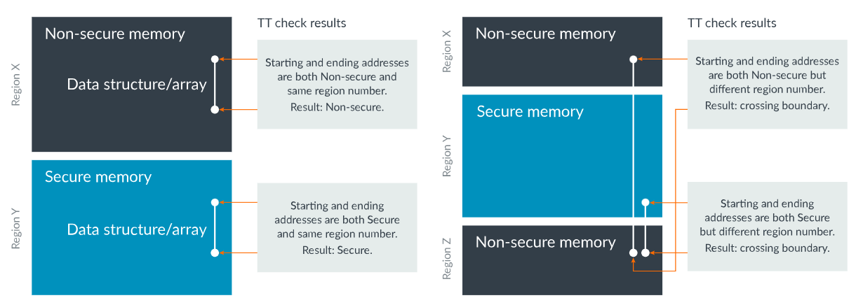
Image: Test-target-instruction.Copyright © 1995-2022 Arm Limited (or its affiliates). All rights reserved.
This mechanism allows security checking at the beginning of the API service (instead of during the operation) to determine if the memory referenced by a pointer from Non-secure software points to the Non-secure address. It prevents Non-secure software from using those APIs in Secure software to access or modify Secure data.
To make these operations easier in a C/C++ programming environment, the Cortex-M Security Extension (CMSE) has defined a range of intrinsic functions for dealing with pointer checks with the TT instructions.
Switching from Secure to Non-secure State#
When the Secure program calls a Non-secure software, the Secure program must use a BLXNS <reg> instruction to invoke the process. If bit 0 of the <reg> is 0, the processor must switch to the Non-secure state when branching to the target address. During the state transition, the return address and some processor state information are pushed onto the Secure stack, while the return address on the Link Register (LR) is set to a special value called FNC_RETURN (0xFEFFFFFF).
The Non-secure function completes by performing a branch (BX LR) to the FNC_RETURN address (bit 0 is 1 to indicate the function was called from the Secure state). It automatically triggers the unstacking of the actual return address from the Secure stack and returns to the calling function. The FNC_RETURN hides the return address of the Secure program from the Non-secure software to avoid the leakage of any secret information. It also prevents Non-secure software from modifying the Secure return address stored in the Secure stack.
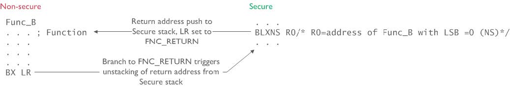
Image: Switching-between-Secure-and-Non-secure-states.Copyright © 1995-2022 Arm Limited (or its affiliates). All rights reserved.
To help software developers declare Non-secure function pointers in C/C++, the Cortex-M Security Extension (CMSE) defines a C function attribute called cmse_nonsecure_call.
GCC:
__attribute__((cmse_nonsecure_call))IAR:
__cmse_nonsecure_call
Software Flow#
The following figure describes a software flow example in a TrustZone implemented system.
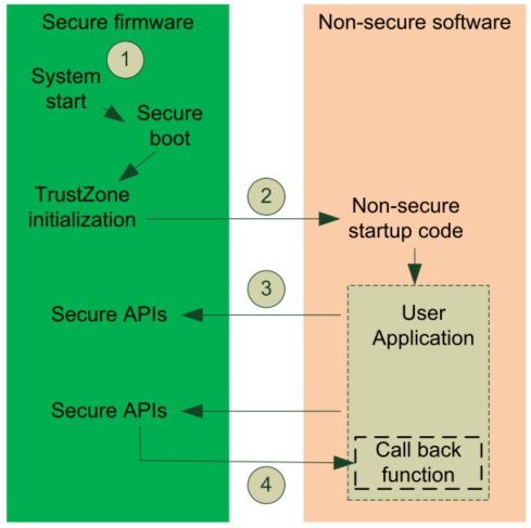
Image: Software Development in ARMv8-M Architecture.Copyright © 1995-2022 Arm Limited (or its affiliates). All rights reserved.
The system starts executing code in the Secure state after a power-on or reset (Secure boot).
The Secure stack pointer (
MSP_S) is set from the address of the Secure vector table (VTOR_S).The Secure Reset Handler pointed by the
VTOR_Sis called.Perform various initialization tasks such as C startup code.
Place peripherals and associated interrupts in either Secure or Non-secure applications.
Program SAU/IDAU to partition the entire memory into Secure, Non-secure Callable, and Non-secure regions.
Program the address of the Non-secure vector table (
VTOR_NS).Initialize the two first entries of the table for the Non-secure stack pointer (
MSP_NS) and Reset Handler to emulate a Non-secure reset.
The Secure firmware branches to the entry point (Reset Handler pointed by the
VTOR_NS) of the Non-secure application.The Non-secure software has its Reset Handler.
Perform various initialization tasks such as C startup code and hardware initialization (e.g., Non-secure peripherals).
It does not conflict with initialization from the Secure code as the stack and heap spaces of Secure and Non-secure code are separated.
During the execution of Non-secure applications, the application could call Secure APIs through the Secure Gateway (SG) veneer in the Non-secure Callable region.
In some cases, Secure APIs might need to call Non-secure call-back functions (e.g., a hardware driver).