TrustZone Implementation#
The goal of TrustZone implementation is to provide Secure Key Storage that can keep access to keys limited to Secure applications while at the same time allowing Non-secure applications to exercise the keys. It is an added feature for the SVM devices that do not have dedicated hardware for Secure Key Storage as in SVH devices.
The PSA Crypto is placed in a Secure region to keep key material hidden from the Non-secure application. The exposed PSA Crypto APIs stay the same while the backend provides persistent key encryption and decryption similar to the key wrapping and unwrapping functionality of the SVH device.
The following items need to be considered when upgrading the existing system for Secure Key Storage with TrustZone.
System Configuration#
The system configuration includes the following items:
Enable system exceptions in the Secure state.
Set the security attributes of different regions in the SAU and ESAU.
Place peripherals and associated interrupts in either Secure or Non-secure applications.
Assign the Bus Masters' security attributes.
The system has two Secure/Non-secure pairs for the bootloader and application. The Secure part of each pair is responsible for properly configuring the split in its Secure application before branching to the Non-secure application.
Note: The secure application will issue a software reset at startup (fatal error) if the device's SE firmware version is lower than the first version that supports TrustZone.
System Exceptions#
The following system exceptions are enabled in the Secure state for the bootloader and application.
MemManage Fault
BusFault
UsageFault
SecureFault
Main Flash Layout#
The following figure is an overview of the main flash layout that covers the isolation requirements for the Secure Key Storage solution. The SAU and ESAU configurations provide the required security to the Cortex-M33 and other Bus Masters during boot and normal operation.

Settings:
The application is set to non-executable (XN) by Secure MPU to avoid any code execution in this area during boot.
The bootloader is set to non-executable (XN) by Secure MPU to avoid any code execution in this area during normal operation.
The ESAU configuration only uses the NSC section by setting mrb01 to the base address of region 0. The reason is that lite ESAU in other Bus Masters treats both S and NSC as a Secure attribute. For the Cortex-M33, the SAU upgrades the NSC in the ESAU to Secure. The 32 bytes region alignment of SAU also relaxes the 4 kB alignment restriction on the start address of the NSC in ESAU.
The whole application area is set to Secure in SAU for Cortex-M33 during boot to hide details from the bootloader NS part.
The ESAU cannot mark any region that comes after a Non-secure section as Secure (must be in the order of S/NSC/NS). Therefore the Secure application area does not align between the Cortex-M33 (SAU + ESAU) and other Bus Masters (lite ESAU) during boot. The secrets stored in that Secure region expose as Non-secure for other Bus Masters during boot (no such issue in normal operations). So the application must not save any plaintext secrets in that Secure region to overcome this limitation during boot.
The NVM storage is in the Non-secure region, so the application must encrypt the persistent keys before storing them in this area.
RAM Layout#
The following figure is an overview of the RAM layout used for the bootloader and application. The SAU and ESAU are used to split the RAM into a Secure and Non-secure region (Non-secure Callable is not required).
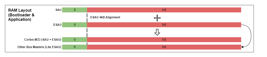
In practice, the Secure part (bootloader or application) takes ownership of the amount of RAM it needs from the beginning of RAM and leaves the rest (up to the ESAU 4 kB alignment requirement) configured as Non-secure.
The bootloader does not know how the application partitions the RAM between Secure and Non-secure. So bootloader removes any secrets from RAM before handing control to the application.
Info Flash and EPPB#
The following figure is an overview of the Info flash and EPPB layout for the application. The Cortex-M33 core is the only Bus Master that can access the EPPB region.

Peripheral and Device#
The following figure is an overview of the peripheral and device layout for the bootloader and application. The SAU and ESAU are used to split the peripheral and device into a Secure and Non-secure region.
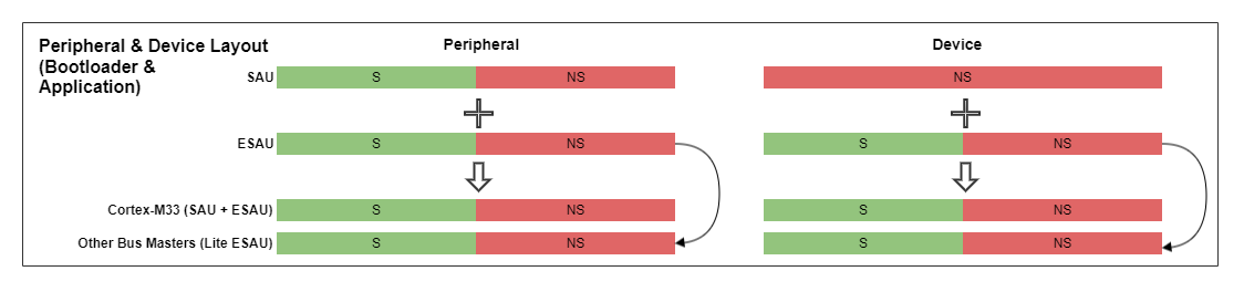
The Secure software is responsible for moving all peripherals and associated interrupts to the Non-secure state at startup, except for the peripherals and interrupts that need to be Secure. The Non-secure software must not include code that attempts to directly access any peripheral that is used by the Secure software.
Peripherals owned by the Secure software (application)
Security Management Unit (SMU)
It prevents Non-secure software from changing the configuration for the ESAUs, BMPUs, and PPUs.
Except for EFR32xG21 devices, some features are also available in the dedicated Non-secure version of SMU registers (
SMU_CFGNS).
CRYPTOACC (VSE devices) or SEMAILBOX (HSE devices)
The crypto engine is placed in the Secure domain for Secure library.
System Configuration (SYSCFG)
It prevents Non-secure software from changing system configurations for Secure software.
Except for EFR32xG21 devices, some features are also available in the dedicated Non-secure version of SYSCFG registers (
SYSCFG_CFGNS).
Memory System Controller (MSC)
It prevents Non-secure software from writing to Secure flash.
Peripheral interrupts owned by the Secure software:
Table: Secure Peripheral Interrupts (Application)
| VSE Device | HSE Device |
| SMU_SECURE_IRQn | SMU_SECURE_IRQn |
| SYSCFG_IRQn | SYSCFG_IRQn |
| MSC_IRQn | MSC_IRQn |
| CRYTOACC_IRQn | SEMBRX_IRQn |
| TRNG_IRQn | SEMBTX_IRQn |
| PKE_IRQn |
The PRIS bit in the AIRCR register is set to 1 to place all Non-secure exceptions/interrupts in lower priority level space. Therefore any Secure exceptions/interrupts can be programmed with higher priority than Non-secure ones.
The BMPUSEC and PPUSEC interrupt enable flags in the SMU_IEN register are set to enable the SMU security fault interrupts (SMU_SECURE_IRQn) on Bus Masters and peripherals.
Floating Point Unit (FPU):
The Secure application does not use the FPU. But the Secure startup code also enables the FPU for use by the Non-secure application.
Bus Masters#
To keep all secrets from the Non-secure world, only the Bus Masters in the table below can access data in the Secure world. For the Bus Masters living in the Secure world, the secure application must configure their corresponding control interfaces in the peripheral space to Secure. The Cortex-M33 core as a Bus Master is split to run in Secure and Non-secure contexts.
Table: Secure Bus Masters (Application)
| Device | Secure Bus Master | Control Interface of Bus Master |
|---|---|---|
VSE | CRYPTOACC | CRYTPOACC |
HSE | SEDMA or SEEXTDMA | SEMAILBOX |
Notes:
Use
SMU_BMPUSATD0register to configure the security attribute of a Bus Master.Use
SMU_PPUSATDnregister to configure the control interface of Bus Master as a Secure peripheral.LDMA is set as a Non-secure Bus Master to make sure it cannot be used to copy out data from the Secure memory.
Application Transitions#
The system contains two Secure/Non-secure pairs.
The [bootloader pair](#bootloader pair) has a Secure bootloader and a Non-secure bootloader containing the communication interfaces.
The [application pair](#application pair) has a Secure application and a Non-secure application consisting of the wireless stacks (if applicable) and application layers.
As described in the preceding sections, the Secure part of these pairs is responsible for setting the security configurations of the system during startup. For the handover between Secure/Non-secure pairs, the software must restore the system so the Secure part of the other pair can execute and reconfigure the system.
The software must reconfigure the following items before transitioning to the next Secure/Non-secure pair:
Restored all peripherals and interrupts to Secure
Reset ESAU to default configuration (all configurable regions to Secure)
Reset SAU to default configuration (Secure for everything)
Reset MPU to default configuration (removes any XN)
Gecko Bootloader#
The Gecko bootloader ensures the Secure assets are protected during the boot flow and normal operation.

The SAU and Secure MPU mark all the flash for application and NVM as Secure and non-executable (XN) during boot. It guards against bootloader NS code execution branching into the application code.
The bootloader needs to split into Secure and Non-secure software to protect secrets in the system. Secure code can access the entire flash to validate or upgrade the system.
For VSE devices, the GBL Decryption Key (AES-128 key) is moved from the NS memory (last page of the main flash) to the Secure part of the bootloader. The Simplicity Commander v1.13 or higher provides a feature to inject the AES-128 key to the bootloader binary file.
commander convert <BL image file> --aeskey <decryption key file> --outfile <BL image with decryption key>The bootloader communication interfaces are placed in the NS area to support various communication components below for firmware upgrades.
BGAPI UART
EZSP-SPI
UART XMODEM
The NS communication functions call into the bootloader APIs placed in the bootloader NSC region. The Secure application validates all input arguments before processing the request.
Before transiting from bootloader to normal operation, it resets the SAU to default configuration to make all the flash for bootloader as Secure.
The Non-secure application software can call bootloader APIs through application NSC, and the corresponding Secure function releases the non-executable (XN) restriction on the bootloader during normal operation.
Secure Library#
The goal of the Secure library is to keep the PSA Crypto key and attestation token protected from malicious code on the NSPE. The following figure overviews multiple components to support the Secure library.
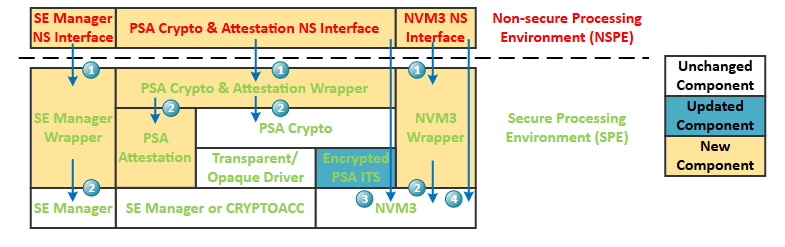
The NS interfaces in NSPE are responsible for packing and passing all input arguments over the NSC functions on wrappers in SPE.
The wrappers in SPE validate all input arguments before calling into the corresponding APIs in different drivers.
Because of the system memory layout limitation, the flash for NVM3 storage is located in the NSPE. Therefore the updated PSA Internal Trusted Storage (ITS) driver needs to encrypt all crypto keys before storing them in Non-secure NVM.
Data stored directly using the NVM3 APIs are not encrypted.
The following table describes the new and updated components of the Secure library.
| Component | Description |
|---|---|
SE Manager NS interface | This component contains SE Manager API callable from the NSPE. It packages the list of input arguments in the appropriate format before calling into the SE Manager wrapper's NSC functions. |
SE manager wrapper | This component contains the interface into SE Manager exposed to the NSPE. These NSC functions grant access to the SE Manager utility API and validate all input arguments before calling into SE Manager. |
PSA Crypto & Attestation NS interface | This component contains PSA Crypto and attestation API callable from the NSPE. It packages the list of input arguments in the appropriate format before calling into the PSA Crypto and attestation wrapper's NSC functions. |
PSA Crypto & Attestation wrapper | This component contains the interface into PSA Crypto and attestation exposed to the NSPE. These NSC functions grant access to the entire PSA Crypto and attestation API and validate all input arguments before calling into PSA Crypto and attestation. |
PSA attestation | This component in SPE provides the functionality required by the PSA attestation specification. |
Encrypted PSA ITS | The PSA ITS layer builds on top of NVM3. This component is updated to support encrypted storage to secure stored keys. The encryption is based on the device's TrustZone Root Key. |
NVM3 NS interface | This component contains NVM3 API callable from the NSPE. It packages the list of input arguments in the appropriate format before calling into the NVM3 wrapper's NSC functions. |
NVM3 wrapper | This component contains the interface into NVM3 exposed to the NSPE. These NSC functions grant access to the NVM3 API and validate all input arguments before calling into NVM3. |
Notes:
The SE Manager NS interface, PSA Crypto NS interface, and NVM3 NS interface in the NSPE provide drop-in replacement on SE Manager utility, PSA Crypto, and NVM3 APIs for existing wireless stacks and user applications.
The NSC calls can only take a limited number of arguments, so all NSC functions take a pointer to a list of parameters to support a long list of arguments. All arguments must be validated using the intrinsic functions from CMSIS.
TrustZone Secure Key Storage#
The TrustZone Secure Key Storage provides a solution to store a user key in Secure RAM or an encrypted form in Non-secure flash.
The TrustZone Root Key stored in the SE NVM for Secure Key Storage encryption is generated or renewed by following operations.
The TrustZone Root Key had already existed if the shipped Series 2 device with SE firmware version supports this key.
Generate a TrustZone Root Key when upgrading from a SE firmware version that did not support this key to the one that does.
Renew a TrustZone Root Key after performing a Device Erase.
Note: The TrustZone Root Key cannot be renewed if Device Erase is disabled.
The TrustZone Root Key is not exposable to the NSPE, and access to this key in SPE is different in HSE and VSE devices.
HSE - The SPE can access the TrustZone Root Key as a built-in non-exportable key in HSE NVM.
VSE - The SPE can access the TrustZone Root Key in Secure RAM, which is copied from VSE NVM during boot.
The TrustZone Root Key value after reset is identical to the value before reset. TrustZone Root Keys are unique on each device. The key allows a user to securely store a key in the Non-secure flash, limiting the number of keys that can be saved only by the amount of Non-secure storage. The following figure describes using the TrustZone Root Key to encrypt a plaintext key and store it in Non-secure NVM.
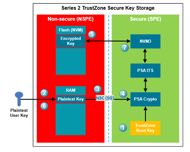
After power-on, the device's TrustZone Root Key is available for the SPE.
A user key is generated and imported into the device's Non-secure memory. In this example, the key is imported into Non-secure RAM for easy deletion, and the key is lost if device power is removed.
Call PSA Crypto API (
psa_import_key()orpsa_generate_key()) through SG in NSC to generate a key for crypto operations.The plaintext key is passed to the PSA Crypto in SPE, where it is encrypted (AES-GCM) with the TrustZone Root Key.
The encrypted key is stored to the NVM in NSPE through the PSA ITS and NVM3 drivers.
The plaintext key can now be deleted from the Non-secure RAM.
Only the PSA Crypto in SPE can retrieve the encrypted key from NVM in NSPE and decrypt it for crypto operations in SPE.
Note: Ignore steps 2 and 6 if the plaintext key is randomly generated by the PSA Crypto.
The following tables describe the storage differences between SVM and SVH devices with and without TrustZone Secure Key Storage (SKS).
| Key Type | Storage on SVM Device | Storage on SVH Device |
|---|---|---|
Volatile Plaintext (without TrustZone SKS) | RAM | RAM |
Persistent Plaintext (without TrustZone SKS) | NVM | NVM |
Volatile Wrapped (without TrustZone SKS) | Not supported | RAM (1) |
Persistent Wrapped (without TrustZone SKS) | Not supported | NVM (1) |
| Key Type | Storage on SVM Device | Storage on SVH Device |
|---|---|---|
Volatile Plaintext (with TrustZone SKS) | Secure RAM (2) | Secure RAM |
Persistent Plaintext (with TrustZone SKS) | Encrypted plaintext key in NS NVM (2) | Encrypted plaintext key in NS NVM |
Volatile Wrapped (with TrustZone SKS) | Not supported | Secure RAM |
Persistent Wrapped (with TrustZone SKS) | Not supported | Encrypted wrapped key in NS NVM |
Notes:
The NVM or NS NVM is at the last part of the main flash.
It is possible to replace the wrapped key solution on the SVH device (1) with TrustZone Secure Key Storage on the SVM device (2), but this is a less secure approach.
PSA Attestation#
The device attestation service creates a token that contains a fixed set of device-specific data when requested by the caller. Each device must have a unique Initial Attestation Key (IAK) pair. The device uses the private IAK to sign the token, and the caller uses the public IAK to verify the token's authenticity.
The generation of the private IAK is different in SVM and SVH devices.
SVM - If the private IAK does not exist in NVM3, it is randomly generated when requested from the PSA Attestation driver and saved to NVM3 through the TrustZone Secure Key Storage.
SVH - The private IAK is generated and securely stored in the HSE during chip production.
An Entity Attestation Token (EAT) is a mini-report that is cryptographically signed. An EAT is encoded in either one of two standardized data formats: a Concise Binary Object Representation (CBOR) or in the text-based format JSON. A digital signature is then used to protect its content. The technical specification defining the content of the EAT, which are claims about the hardware and the software running on a device, is specified by the Internet Engineering Task Force (IETF).
The EAT is a crypto-signed report card with claims. A claim is a data item that is represented as a Key-Value pair. Claims can relate to the device's pedigree or anything one wants the device to attest. Collected data can originate from the Root of Trust (RoT), any protected area, or non-protected areas.
The EAT must be signed following the structure of the CBOR Object Signing and Encryption (COSE) specification. For asymmetric key algorithms, the signature structure must be COSE-Sign1. A COSE-Sign1 is a CBOR encoded, self-secured data blob that contains headers, a payload, and a signature.
The primary need for EAT verification is to check correct formation and signing as for any token. In addition, though, the verifier can operate a policy where values of some of the claims in this profile can be compared to reference values that are registered with the verifier for a given deployment, to confirm that the device is endorsed by the manufacturer supply chain.
The PSA attestation token (aka Initial Attestation Token - IAT) is a profiled EAT. The Series 2 device will generate this token by (Nonce claim below) unless the SE OTP is uninitialized or the SECURE_BOOT_ENABLE option in SE OTP is disabled.
The following tables describe claims used in the PSA attestation token of the Series 2 device.
Table: Claims of PSA Attestation Token
| Key | Claim Name (Present) | Claim Description | Claim Value |
|---|---|---|---|
265 (-75000) | Profile Definition (Must) | The Profile Definition claim encodes the unique identifier corresponds to the EAT profile. | http://arm.com/psa/2.0.0 |
2394 (-75001) | Client ID (Must) | The Client ID claim represents the security domain of the caller. | See note below (2 byes) |
2395 (-75002) | Security Lifecycle (Must) | The Security Lifecycle claim represents the current lifecycle state of the PSA RoT. | Device dependent (2 bytes) |
2396 (-75003) | Implementation ID (Must) | The Implementation ID claim uniquely identifies the implementation of the immutable PSA RoT. | Device dependent (32 bytes) |
2397 (-75004) | Boot Seed (Optional) | The Boot Seed claim represents a value created at system boot time that will allow differentiation of reports from different boot sessions. | Device dependent (32 bytes) |
2399 (-75006) | Software Components (Must) | The Software Components claim is a list of software components that includes all the software loaded by the PSA RoT. | See note below |
10 (-75008) | Nonce (Must) | The Nonce claim is used to carry the challenge provided by the caller to demonstrate freshness of the generated token. The length must be either 32, 48, or 64 bytes. | Random nonce (32/48/64 bytes) |
256 (-75009) | Instance ID (Must) | The Instance ID claim represents the unique identifier of the IAK. The length must be 33 bytes. | SHA-256 hash of public IAK (32 bytes) with header 0x01 |
Notes:
Some claims MUST be present in a PSA attestation token.
The keys
-7500xwere defined in a previous version of the PSA attestation token specification (PSA_IOT_PROFILE_1profile) that is still used in the HSE-SVH firmware.The actual claims returned from the tokens on the SVH device are HSE firmware version-dependent.
Key 2394: In PSA, a security domain is represented by a signed integer where negative values represent callers from the NSPE and positive IDs represent callers from the SPE. The value 0 is not permitted.
Key 2395 (For the definitions of these lifecycle states, refer to the ARM PSA Security Model):
UNKNOWN (
0x0000 - 0x00ff)ASSEMBLY_AND_TEST (
0x1000 - 0x10ff)PSA_ROT_PROVISIONING (
0x2000 - 0x20ff)SECURED (
0x3000 - 0x30ff)NON_PSA_ROT_DEBUG (
0x4000 - 0x40ff)RECOVERABLE_PSA_ROT_DEBUG (
0x5000 - 0x50ff)DECOMMISSIONED (
0x6000 - 0x60ff)
Key 2396:
Word[0]: Die revision
Word[1]: SE OTP version (return 0 for VSE SE firmware < v1.2.14)
Word[2]: Security capability (not applicable to HSE-SVH device, always returns 1 in this word)
0: Unknown security capability
1: Security capability not applicable
2: Basic security capability
3: Root of Trust security capability
4: HSE-SVM security capability
5: HSE-SVH security capability (run HSE-SVM binary on HSE-SVH device)
Word[3]: Production version
Word[4:7]: Reserved (zeros)
Key 2399: Each software component uses the attributes described in the following table, and some MUST be present in a software component claim.
| Key | Attribute (Present) | Description | Value |
|---|---|---|---|
1 | Measurement Type (Optional) | The Measurement Type attribute is a short string representing the role of this software component. | See note below |
2 | Measurement Value (Must) | The Measurement Value attribute represents a hash of the invariant software component in memory at startup time. | SHA-256 hash (32 bytes) of the firmware |
4 | Version (Optional) | The Version attribute is the issued software version in the form of a text string. | A string of 8 bytes |
The following measurement types may be used for Key 1:
"BL": a Bootloader
"PRoT": a component of the PSA Root of Trust
"ARoT": a component of the Application Root of Trust
"App": a component of the NSPE application
"TS": a component of a Trusted Subsystem
The PSA Attestation API allows access to the PSA attestation token, so an external entity can cryptographically verify the identity and trust status of the device.
Table: PSA Attestation API
| PSA Attestation API | Usage |
|---|---|
psa_initial_attest_get_token | Retrieve the PSA attestation Token. |
psa_initial_attest_get_token_size | Calculate the size of a PSA attestation Token. |
sl_tz_attestation_get_public_key | Get the public IAK key for PSA attestation token signature verification. |
Note: The
sl_tz_attestation_get_public_keyis a Silicon Labs custom API.
SE Manager#
SE Manager is the foundation for the Secure library cryptographic operations on HSE devices. It means that SE Manager has to move into the SPE.
The following SE Manager core APIs are always available in the NSPE.
| SE Manager Core API | VSE-SVM | HSE-SVM | HSE-SVH |
|---|---|---|---|
sl_se_init | Y | Y | Y |
sl_se_deinit | Y | Y | Y |
sl_se_init_command_context | Y | Y | Y |
sl_se_deinit_command_context | Y | Y | Y |
sl_se_set_yield | Y | Y | Y |
The following SE Manager core APIs expose to the NSPE through the NSC interface for the VSE devices.
| SE Manager Core API | VSE-SVM | HSE-SVM | HSE-SVH |
|---|---|---|---|
sl_se_read_executed_command | Y | - | - |
sl_se_ack_command | Y | - | - |
The following SE Manager utility APIs expose to the NSPE through the NSC interface for configuring the security features of HSE or VSE devices.
| SE Manager Utility API | VSE-SVM | HSE-SVM | HSE-SVH |
|---|---|---|---|
sl_se_check_se_image | Y | Y | Y |
sl_se_apply_se_image | Y | Y | Y |
sl_se_get_upgrade_status_se_image | Y | Y | Y |
sl_se_check_host_image | Y | Y | Y |
sl_se_apply_host_image | Y | Y | Y |
sl_se_get_upgrade_status_host_image | Y | Y | Y |
sl_se_init_otp_key | Y | Y | Y |
sl_se_read_pubkey | Y | Y | Y |
sl_se_init_otp | Y | Y | Y |
sl_se_read_otp | Y | Y | Y |
sl_se_get_se_version | Y | Y | Y |
sl_se_get_debug_lock_status | Y | Y | Y |
sl_se_apply_debug_lock | Y | Y | Y |
sl_se_get_otp_version | Y | Y | Y |
sl_se_write_user_data | - | Y (EFR32xG21 only) | Y (EFR32xG21 only) |
sl_se_erase_user_data | - | Y (EFR32xG21 only) | Y (EFR32xG21 only) |
sl_se_get_reset_cause | - | Y (EFR32xG21 only) | Y (EFR32xG21 only) |
sl_se_get_status | - | Y | Y |
sl_se_get_serialnumber | - | Y | Y |
sl_se_enable_secure_debug | - | Y | Y |
sl_se_disable_secure_debug | - | Y | Y |
| SE Manager Utility API | VSE-SVM | HSE-SVM | HSE-SVH |
|---|---|---|---|
sl_se_set_debug_options | - | Y | Y |
sl_se_erase_device | - | Y | Y |
sl_se_disable_device_erase | - | Y | Y |
sl_se_get_challenge | - | Y | Y |
sl_se_roll_challenge | - | Y | Y |
sl_se_open_debug | - | Y | Y |
sl_se_disable_tamper | - | - | Y |
sl_se_read_cert_size | - | - | Y |
sl_se_read_cert | - | - | Y |
Note: The NSPE cannot access the other SE Manager APIs for cryptographic and attestation operations.
Common Vulnerabilities and Exposures (CVE)#
At this writing, the following known TrustZone CVE had been fixed in the current implementation.
CVE-2020-16273: Stack sealing
CVE-2021-36465: VLLDM instruction/floating-point vulnerability