Developing with WiSeConnect™ SDK v3.x with the SiWx91x Host™#
This guide describes how to develop applications for the SiWx91x™ chipset family using the WiSeConnect™ SDK v3.x in System-on-chip (SoC) mode, where both the application and the connectivity stack run on the SiWx91x chipset.
Note: The output images in this guide are for illustration purposes only. Details such as board names and version numbers may not exactlyb match the product.
Check Prerequisites#
Software#
Simplicity Studio
Gecko software development kit (GSDK)
Note:
We recommend using the latest GSDK version.
Refer to the Release Notes for the GSDK version tested with this release.
Hardware#
Wi-Fi Access Point (802.11 ax/b/g/n)
SiWx917 SoC development boards or kits. See the Check Prerequisites > Hardware section on the Starting in SoC Mode page.
Windows/Linux/MacOS computer with a USB port
Type C USB cable compatible with the computer's USB port (for e.g., type C to type A if the computer has a type A USB port).
Setup Software#
You may setup the following software in this section while waiting to receive the hardware:
Install Simplicity Studio#
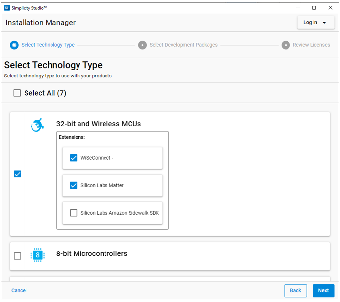
Download the latest version of Simplicity Studio and follow the installation instructions. During the installation:
make sure you log in to Simplicity Studio in the Installation Manager window,
select Install by technology type, and
select the WiSeConnect extension under 32-bit and Wireless MCUs.
Install the GNU ARM v12.2.1 Toolchain#
Note: From v4.4.0 on, Gecko SDK (GSDK) requires v12.2.1 of the GNU ARM toolchain to compile a project successfully. Follow the instructions in this section to install this toolchain version and configure it for your new projects.
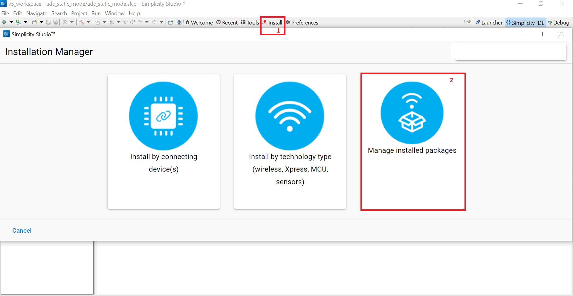
Log in to Simplicity Studio if not already done.
In the Simplicity Studio home page, select Install > Manage installed packages.
Select the Toolchains tab.
Click Install next to GNU ARM Toolchain (v12.2.rel1.xxxx.x) - 12.2.yyyy, where xxxx.x and yyyy may vary depending on the toolchain minor or patch version.
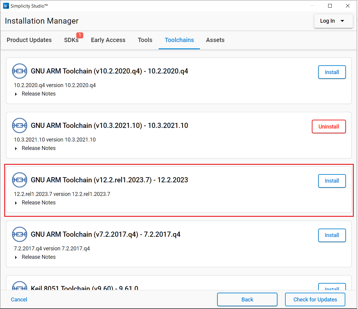
The toolchain will be installed.
Close the Installation Manager window.
Click Preferences.
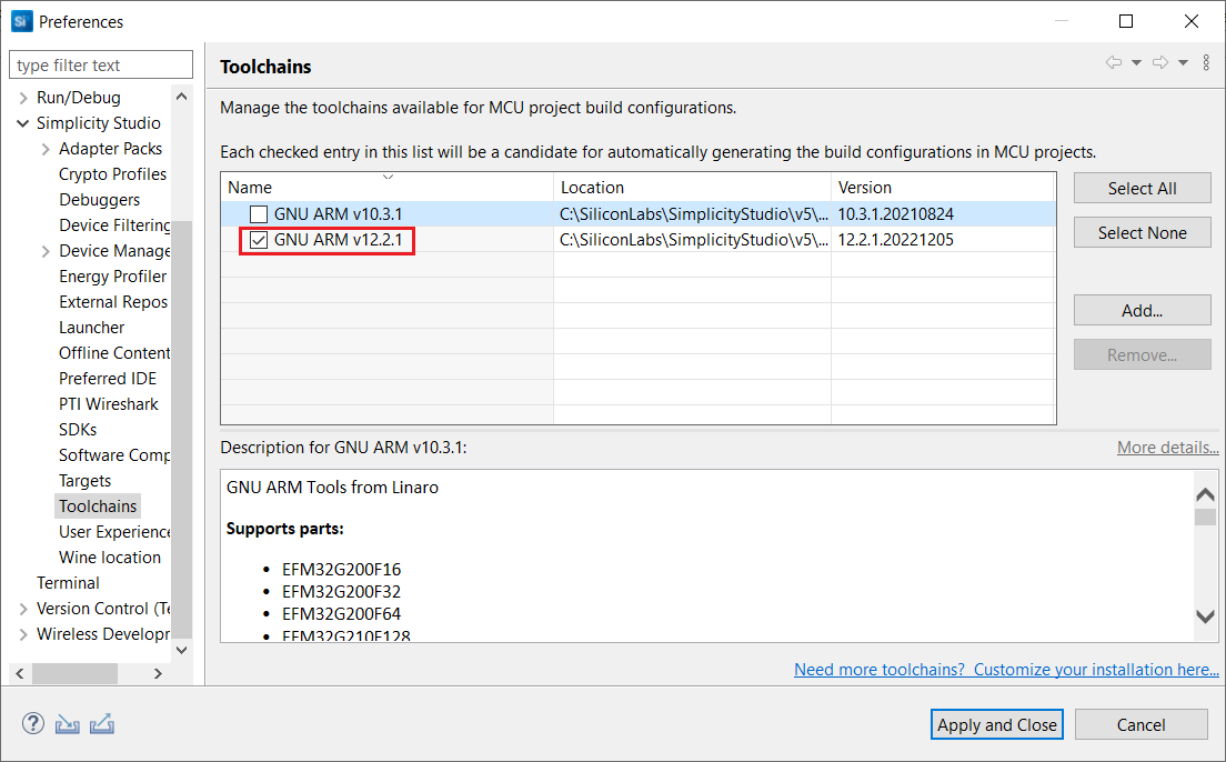
Expand the Simplicity Studio section in the Preferences dialog and select the Toolchains section.
Select GNU ARM v12.2.1 and un-select all other toolchains shown.
Click Apply and Close.
Note: If you have an existing project, see Silicon Labs community page for instructions to configure the toolchain version in your project.
Install the WiSeConnect 3 Extension#
If you already selected the WiSeConnect extension in the Install Simplicity Studio section, you may skip this section.
Before installing the WiSeConnect 3 extension, upgrade to a compatible GSDK version if not already done. See the Prerequisites section for the supported GSDK versions.
You may install WiSeConnect 3 through one of the following alternative paths:
Installation Manager (recommended)
Manage SDKs Window (hardware required)
Install WiSeConnect 3 through the Installation Manager#
Log in to Simplicity Studio if not already done.
In the Simplicity Studio home page, select Install > Manage installed packages.
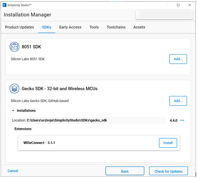
Select the SDKs tab.
Next to the WiSeConnect - 3.x.x extension, click Install.
Install WiSeConnect 3 through the Manage SDKs Window#
Note: You must have the hardware available before using these steps to install the WiSeConnect 3 extension.
Download the WiSeConnect v3.x source code from the following URL after substituting 3.x.x with the desired release version:
https://github.com/SiliconLabs/wiseconnect/archive/refs/tags/v3.x.x.zipIf you don't know your release version, go to the GitHub Releases Page and select the version to download.
Unzip the downloaded
wiseconnect-3.x.x.zipfile. It will be extracted into a folder structure similar to the following:wiseconnect-3.x.x |--- wiseconnect-3.x.x |------ <source code>Launch Simplicity Studio and log in.
Connect the SiWx91x to your computer.
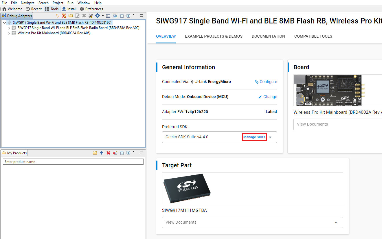
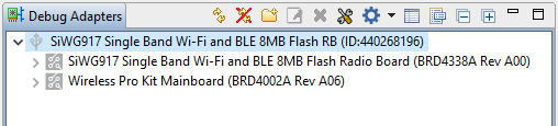
In the Debug Adapters pane, select your radio board.
In the General Information section, click Manage SDKs.
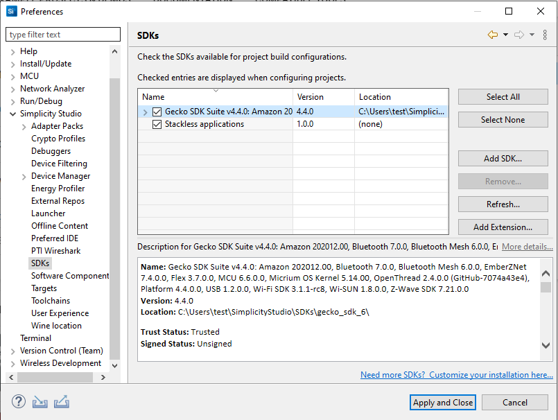
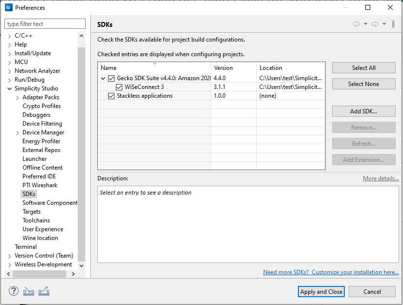
The Preferences window will be opened in the SDKs section.
Select Gecko SDK Suite vx.x.x and click Add Extension.
In the Add SDK Extensions window, click Browse.
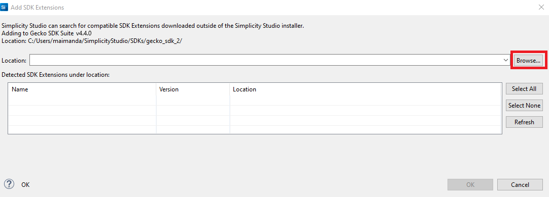
Locate and select the
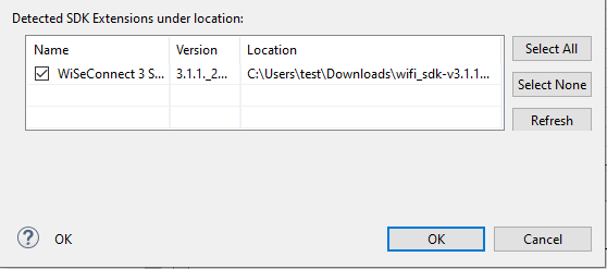
wiseconnect-3.x.xsub-folder extracted in step 2 above which contains the source code.Studio will detect the WiSeConnect 3 SDK extension.
Select the detected extension and click OK.
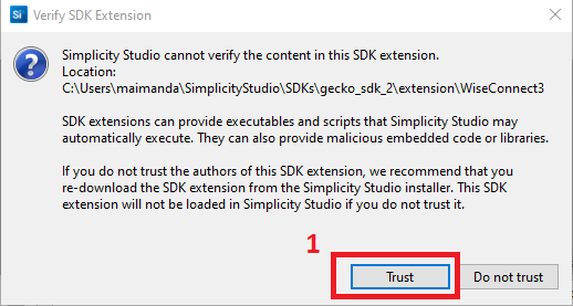
If a Verify SDK Extension popup is displayed, click Trust.
The selected WiSeConnect 3 extension will be displayed.
Click Apply and Close.
Connect SiWx91x to Computer#
Connect the WPK board to your computer using a USB cable.
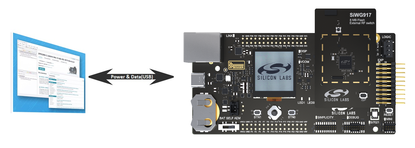
Simplicity Studio will detect and display your radio board.
Troubleshoot a Board Detection Failure#
If Simplicity Studio does not detect your radio board, try the following:
In the Debug Adapters pane, Click the Refresh button (having an icon of two looping arrows).
Press the RESET button on the WPK board.
Power-cycle your device by disconnecting and reconnecting the USB cable.
Upgrade SiWx91x Connectivity Firmware#
Note: The flash memory map has been modified with WiSeConnect SDK v3.1.1. If you have an older radio board, you must migrate to the new memory map before flashing any firmware. Please follow the SiWG917 – TA Flash Memory Map Change Guide to perform a migration.
We recommend that you upgrade the SiWx917 connectivity firmware to the latest available version when:
you first receive an SiWx917 Pro kit
you first receive a radio board, or
you upgrade to a new version of the WiSeConnect 3 extension
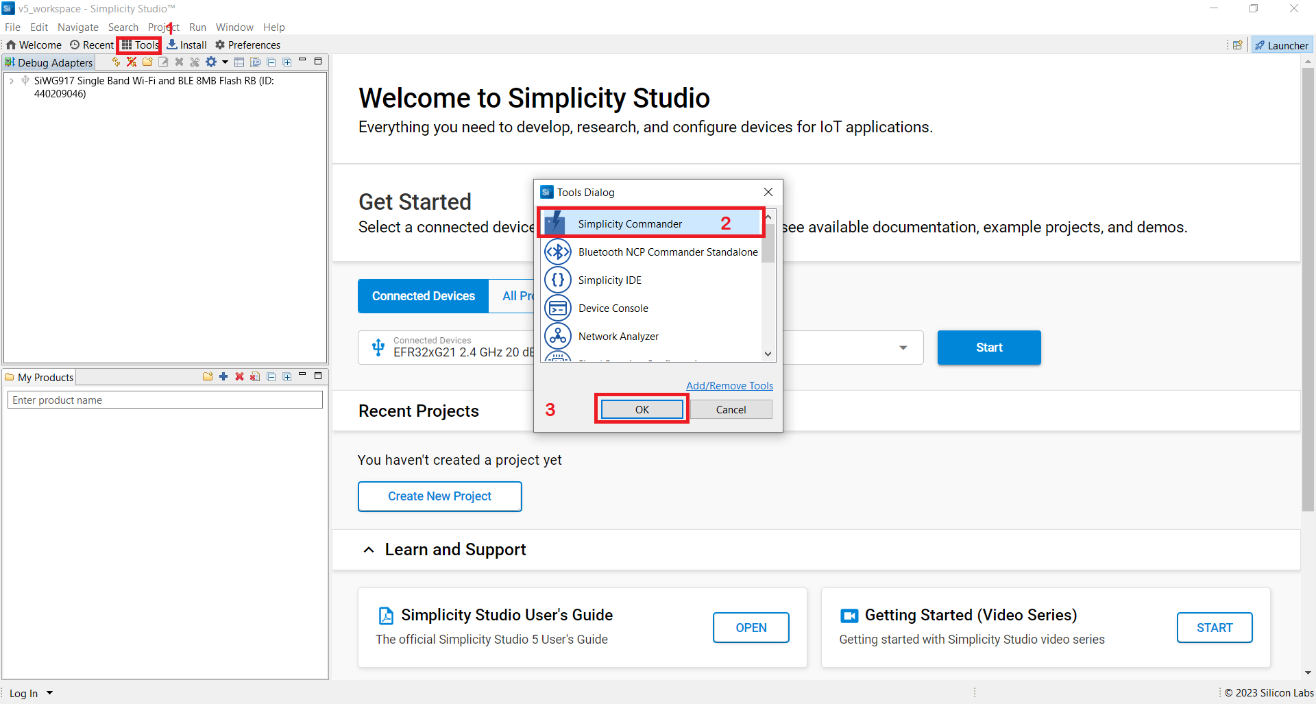
In the Simplicity Studio home page, click Tools.
In the Tools dialog, select Simplicity Commander and click OK.
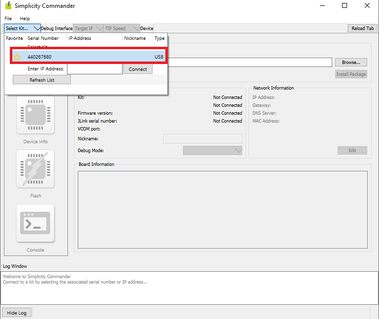
In the Simplicity Commander window, click Select Kit and choose your radio board.
In the navigation pane, go to the Flash section.
Click Browse next to the Binary File field.
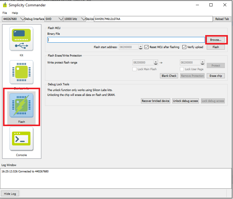
Locate and select the firmware file to flash from within the
connectivity_firmwaresub-folder of the WiSeConnect 3 extension path.Note:
If you don't see any files in the sub-folder, select All files in the file filter field in the Browse dialog.
The WiSeConnect 3 extension path is the one where the extension was downloaded during installation. If you're not sure what the path is, you may refer to the location in the Preferences > SDKs page shown on clicking Manage SDKs.
Click Flash.
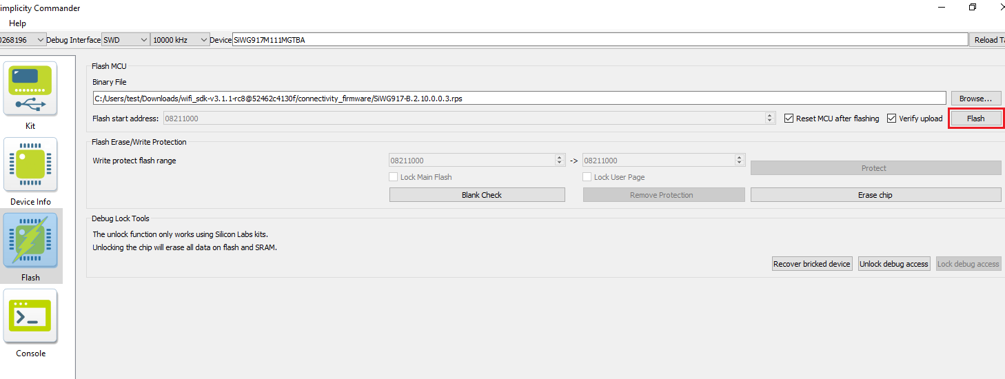
The firmware will be flashed and the Log Window will display the message: "Flashing completed successfully!"
Troubleshoot Firmware Update Failure#
If the firmware update fails, try the following:
Toggle the power switch towards AEM (Advanced Energy Monitoring) on the WPK board
Try the following steps:
Press and hold the ISP button on the radio board.
Press and release the RESET button on the WPK board.
Release the ISP button on the radio board.
In the Flash section in step 5 above, click Erase chip.
The flash will be erased.
Press the RESET button on the WPK again.
Retry the firmware upgrade.
In case studio failed to detect your board, see the Troubleshoot a Board Detection Failure section.
Create Project#
Log in to Simplicity Studio and connect the SiWx91x to your computer.
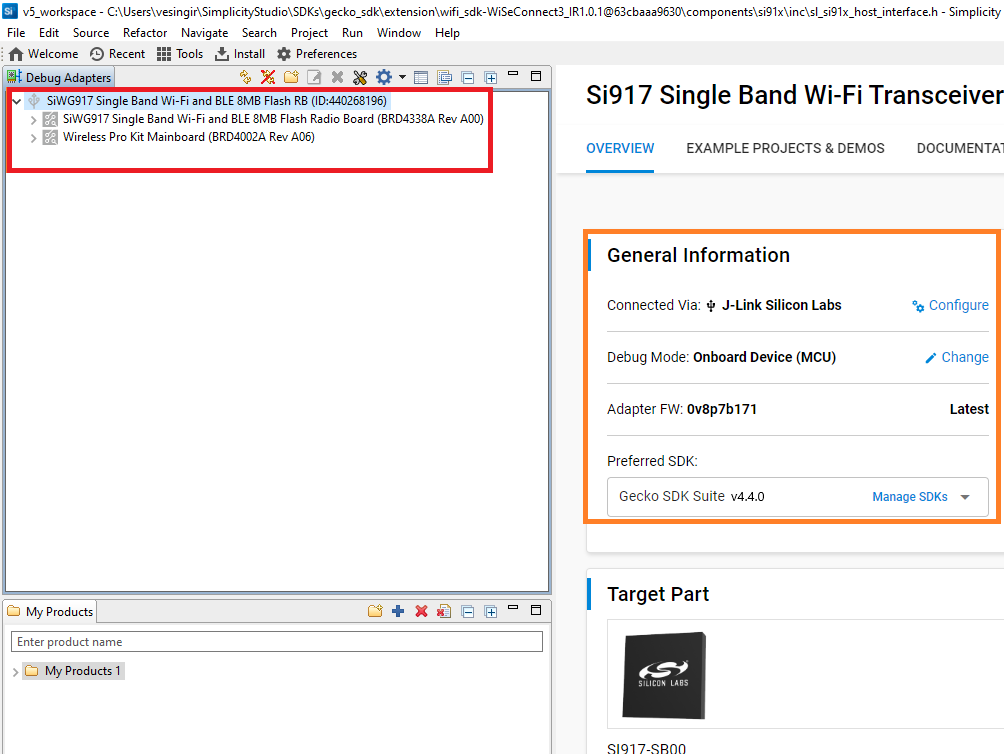
Go to the Debug Adapters section.
Select your radio board from the displayed list.
The Launcher page will display the selected radio board's details.
Select the OVERVIEW tab.
Verify the following in the General Information section:
The Debug Mode is Onboard Device (MCU).
The Preferred SDK is the version you selected earlier.
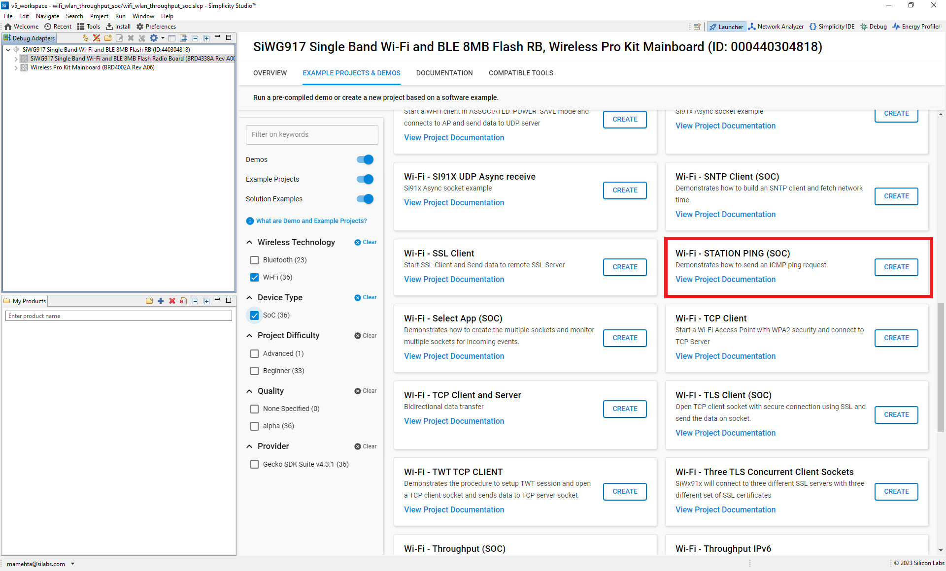
Select the EXAMPLE PROJECTS AND DEMOS tab.
Locate the example you want and click CREATE.
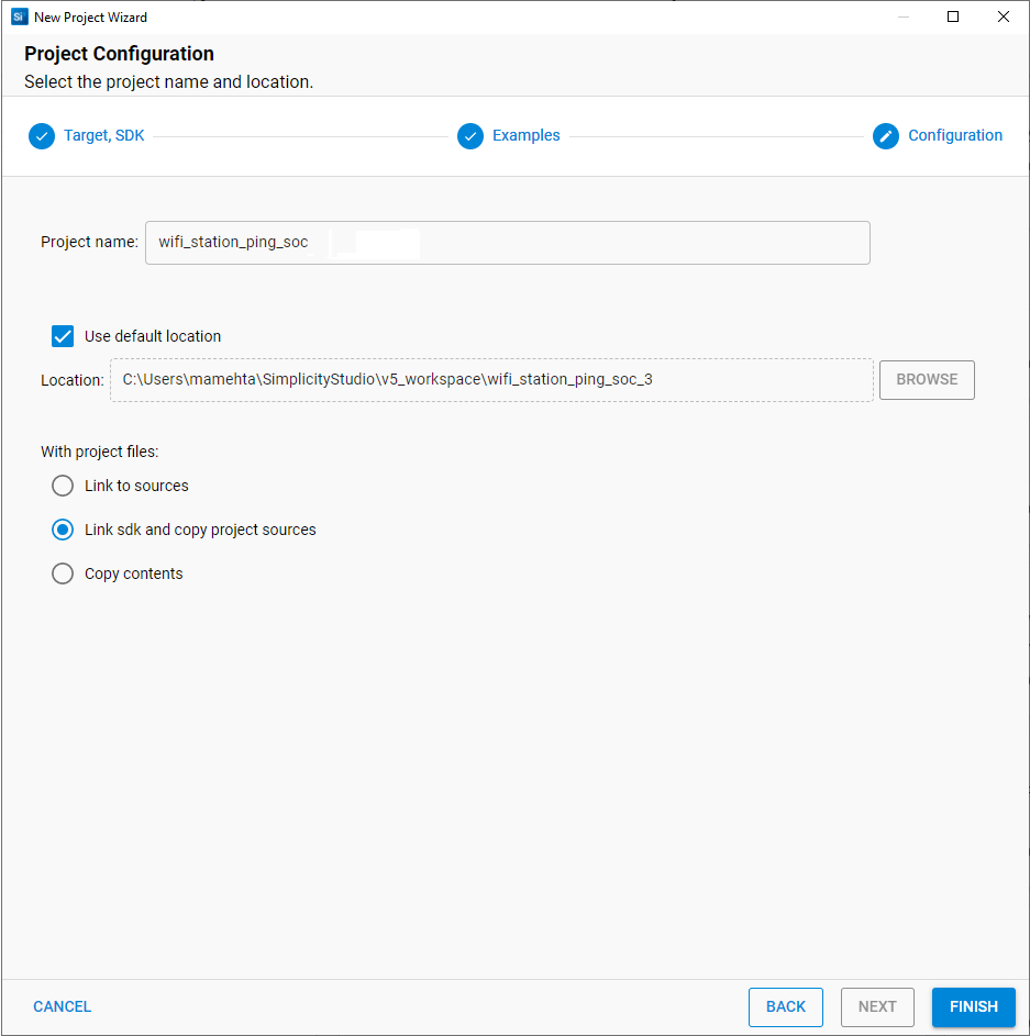
In the New Project Wizard window, click FINISH.
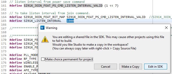
Note: The Copy contents option is not currently supported.
Note: The Make a Copy option is not currently supported while editing a shared SDK file, when prompted to either make a copy of the file or edit it in the SDK itself.
Configure an Application#
Configure the settings for your example. For Wi-Fi - STATION PING (SOC) (the recommended example for this guide) or for other examples, see the Application Build Environment section in the README page for configuration instructions.
You may use the Component Editor to configure the components in your example.
Build an Application#
Launch Simplicity Studio and log in.
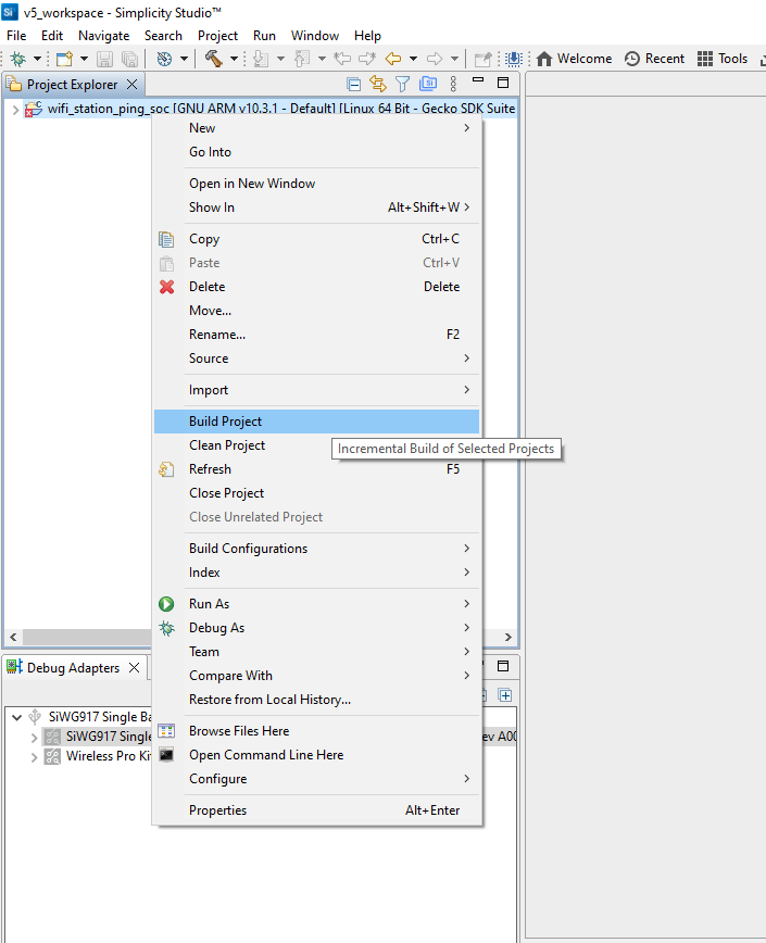
In the Project Explorer pane, right-click the project name and select Build Project.
You may also click the Build button with a hammer icon on the Simplicity IDE perspective toolbar.
Flash an Application#
Note: The SiWx91x SoC comes pre-flashed with a bootloader. A bootloader image does not need to be flashed separately.
Note: The flash memory map has been modified with WiSeConnect SDK v3.1.1. If you have an older radio board, you must migrate to the new memory map before flashing any firmware. Please follow the SiWG917 – TA Flash Memory Map Change Guide to perform a migration.
There are two alternative methods to flash an application to the application processor of the SiWx91x device:
Once you flash the Wi-Fi - STATION PING (SOC) example (the recommended example for this guide), you may refer to the Test the Application section of its README page to explore its output. The other sections of the README like the Purpose/Scope section and Overview section (not present in some README's) provide more information about the example.
See the Examples page to explore all available examples and view their README pages.
Flash an Application Built Using Simplicity Studio#
Build the application as described in the Build an Application section.
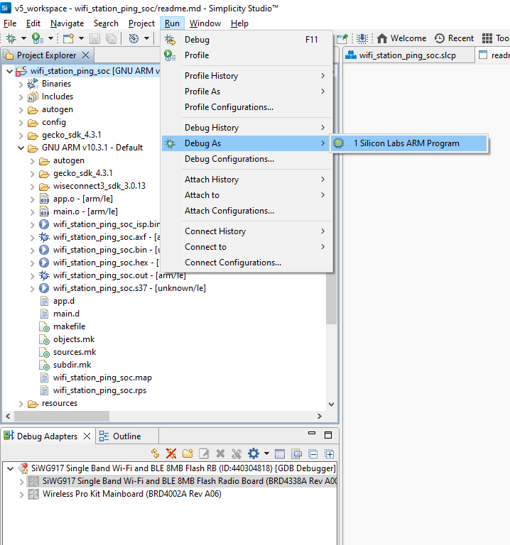
In the Project Explorer pane, right-click on your project name and select Run As > 1 Silicon Labs ARM Program.
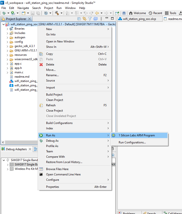
The application binary will be flashed on the radio board and the application will start running.
View the standard output or enter input data as needed. See the Console Input and Output section.
Note: See the troubleshooting section in case the application fails to flash.
Flash an Application Binary#
If the binary was built as described in the Build an Application section, a file with a
.rpsextension is generated. This file will be available under GNU ARM vXX.x.x - Default in the users workspace. To see its location in your computer's file system, right-click on the.rpsfile and select Show In > System Explorer.Alternatively, you may have obtained a
.rpsfile through another means such as someone else building and providing the binary to you.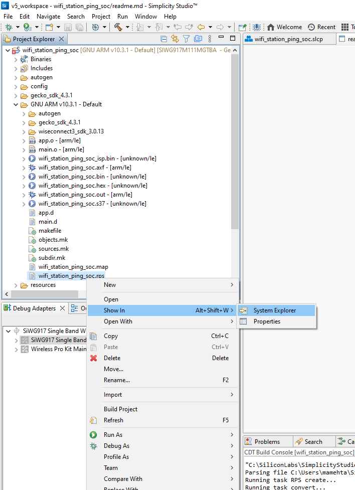
The instructions to flash the application binary are almost the same as those for flashing an SiWx91x firmware file, except for the point noted below:
Instead of choosing the SiWx91x firmware file, select the
.rpsyou obtained in step 1 above.
Note: If you don't see
.rpsfiles in the sub-folder, select All files in the file filter field in the Browse dialog.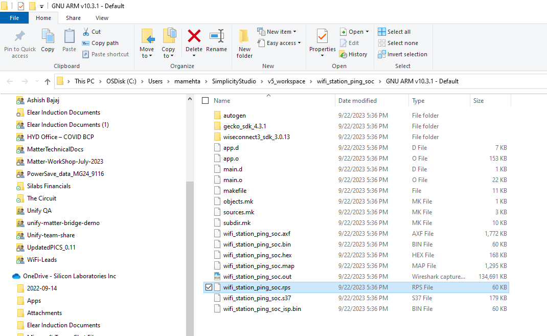
Troubleshoot an Application Flash Failure#
The application may fail to flash for one of the following reasons:
Error code 102 is displayed in the logs, indicating that ISP mode is enabled. Try the following steps:
Press and hold the ISP button on the radio board.
Press and release the RESET button on the WPK board.
Release the ISP button on the radio board.
Retry flashing the application.
"Could not connect debugger. Could not connect to target device" is displayed in the logs, indicating that the application processor is in a low power state with no flash access. Try the same steps as those described above for error 102.
Unknown reason - try re-launching Simplicity Studio.
For additional tips, see the Troubleshoot Firmware Update Failure section. Follow the suggested steps and then, instead of retrying the connectivity firmware update, retry flashing the application.
Configure the Debugger#
Note: Application debugging currently does not work. This is a known issue and has two alternative workarounds:
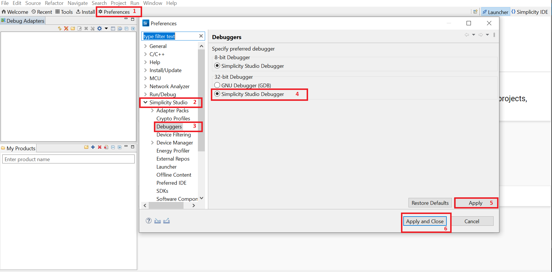
Configure the Simplicity Studio Debugger#
Open Simplicity Studio.
Click Preferences.
In the Preferences window, select Simplicity Studio > Debuggers.
Select Simplicity Studio Debugger and click Apply.
Click Apply and Close.
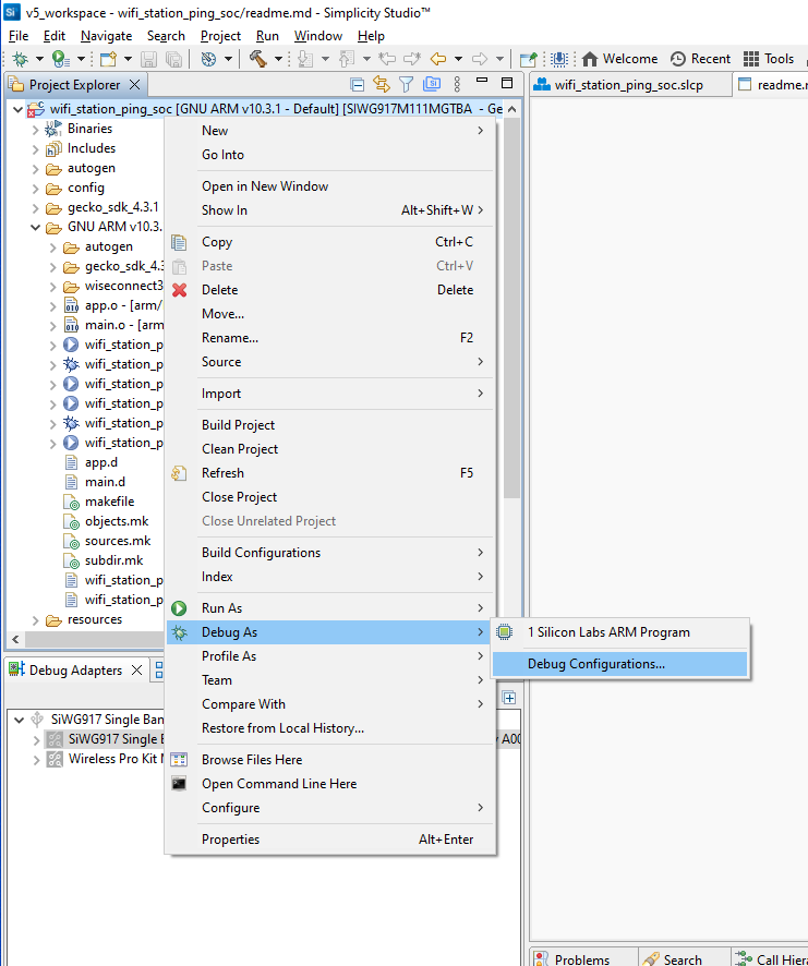
Configure the GDB Debugger#
In the Project Explorer pane, right-click on your project name and select Debug As > 1 Silicon Labs ARM Program.
Studio will switch to debug mode and fail to halt execution at
main()as described in the debugging section.Close the Debug pane.
In the Project Explorer pane, right-click on your project name and select Debug As > Debug Configurations.
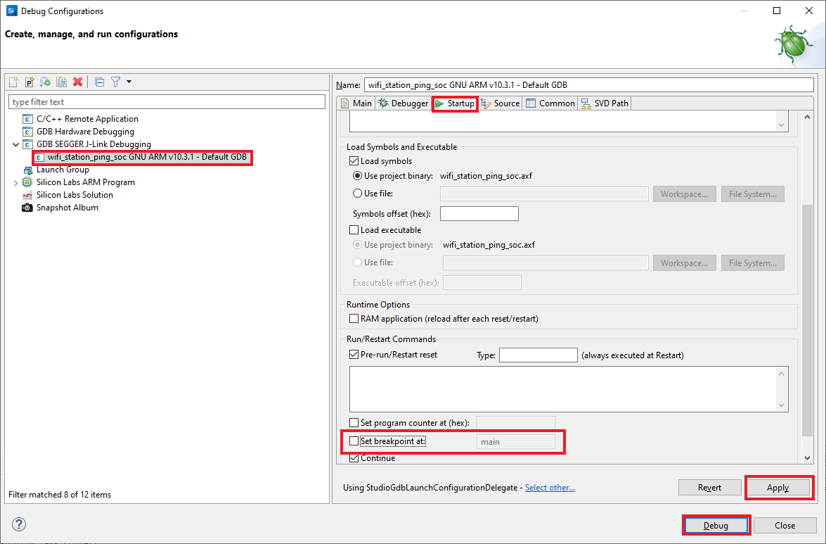
Under GDB SEGGER J-Link Debugging, select your project name.
Select the Startup tab.
Unselect the Set breakpoint at field.
Click Apply and click Debug.
Debug an Application#
In the Project Explorer pane, select your project name.
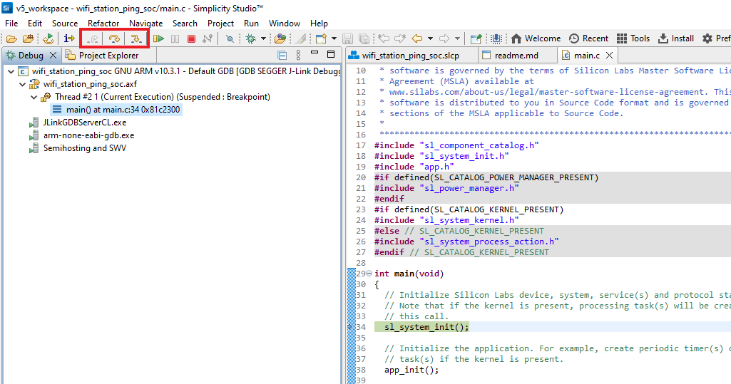
From the menu, select Run > Debug As > 1 Silicon Labs ARM Program.
Studio will switch to debug mode and halt execution at the
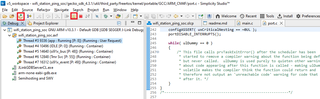
main()function in your application.Add a break point in the desired location of the code and click the Resume button (having an icon with a rectangular bar and play button).
Execution will halt at the break point.
Use the following debug functions to direct the execution of the code:
Step In button (having an icon with a arrow pointing between two dots).
Step Over button (having an icon with an arrow going over a dot).
Step Out button (having an icon with an arrow pointing out from between two dots).
View the standard output or enter input data as needed. See the Console Input and Output section.
Troubleshoot an Application Debug Failure#
The application may fail to enter the debug mode due to one of the following reasons:
Studio failed to halt execution at the
main()function. Perform the following steps before trying again:Click the Suspend button (having a pause button icon).
Click the Reset button (having an icon of a play button with an arrow underneath).
Retry debugging the application.
For additional tips, see the Troubleshoot an Application Flash Failure section. Follow the suggested steps and then, instead of retrying the flashing of the application, retry debugging the application.
Console Input and Output#
Connect your WPK board to your computer.
Open Simplicity Studio.
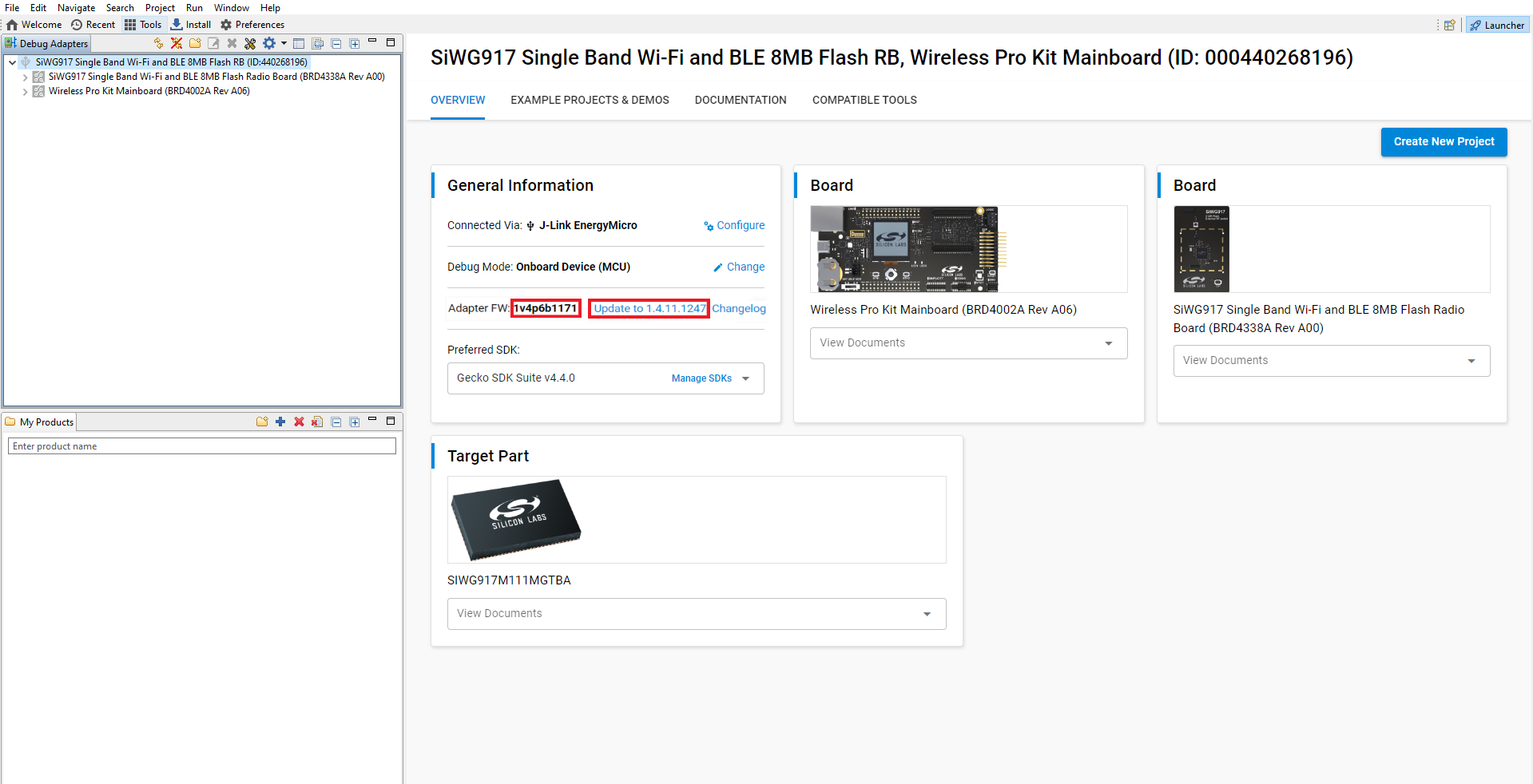
In the Debug Adapters pane, select your WPK board.
The Adapter FW field shows your WPK board's current firmware version, similar to 1vnpxxbyyy, where n is the major version, xx is the patch version number and yyy is the build number.
Click Update to 1.4.xx.yyyy if the version is before 1v4p10b215, or in other words:
Major version = 4 and one of the following is true:
patch < 10 or
patch = 10 and build < 215
The firmware will be upgraded on your WPK board.
In the Debug Adapters pane, right-click on your radio board and click Launch Console.
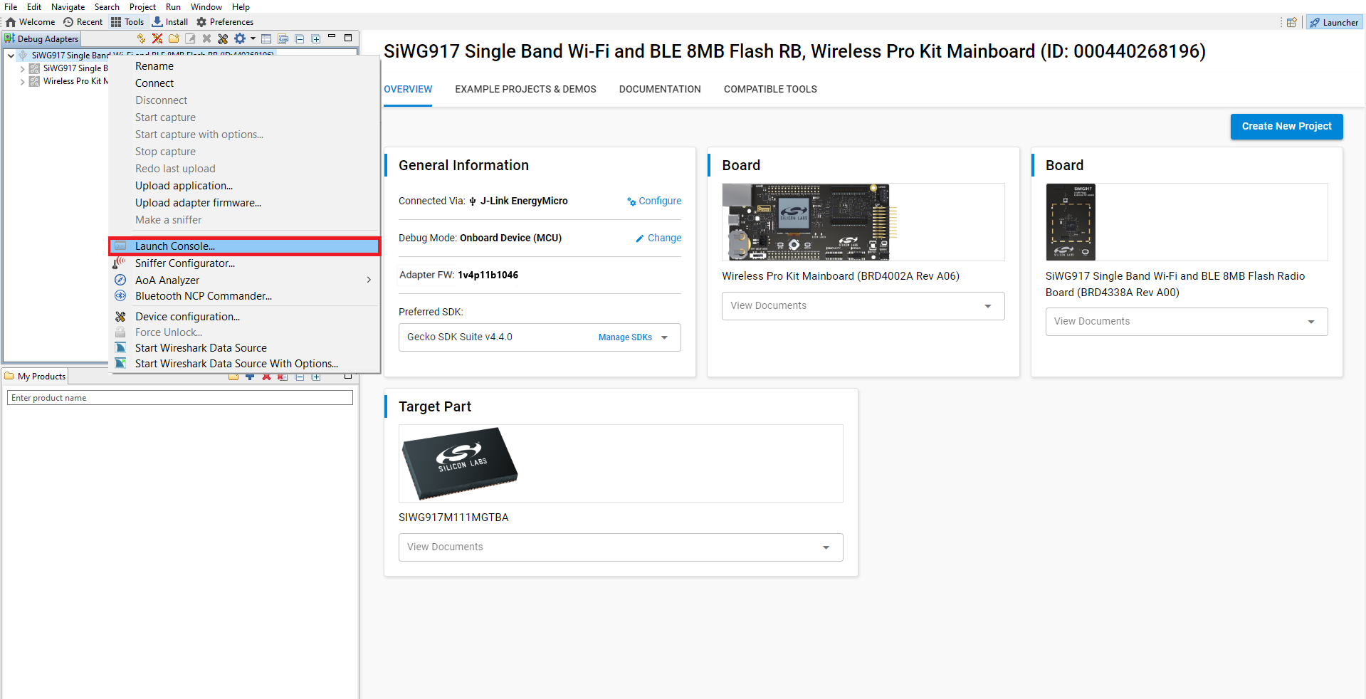
Select the Admin tab and press Enter to see the
WPK>prompt.Enter the following command to set the baud rate:
pti config 0 vuart 115200Select the Serial 1 tab.
Place the cursor inside the text input field and hit Enter.
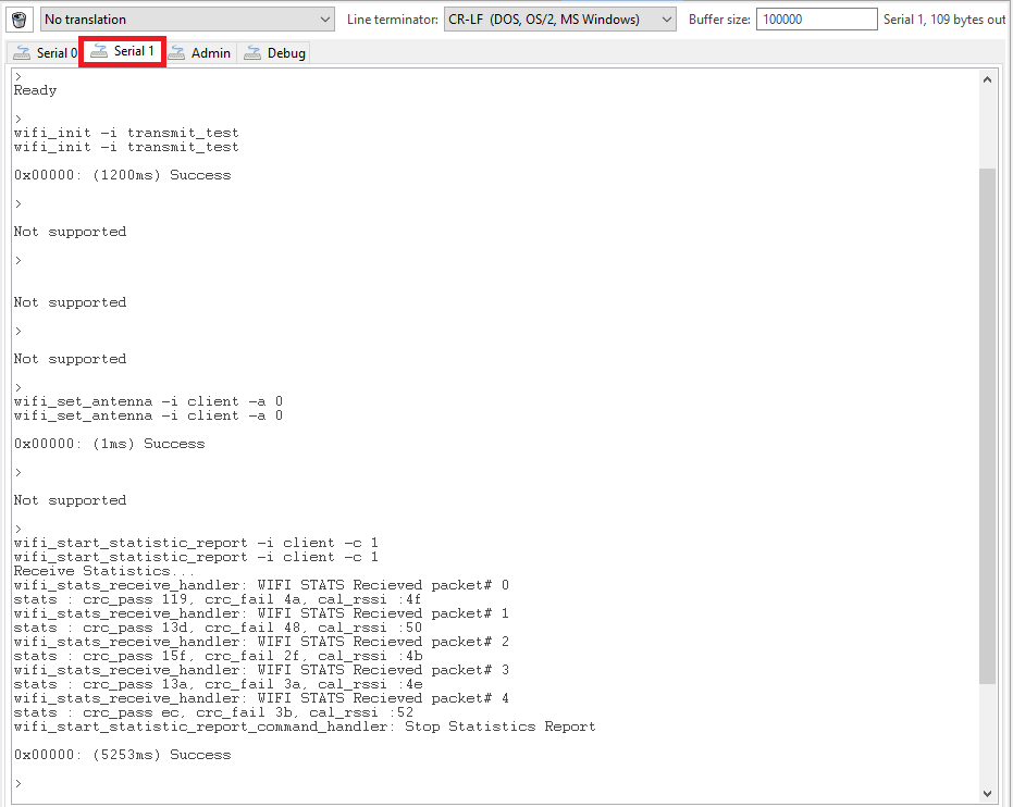
Console output will start getting displayed in the Serial 1 tab.
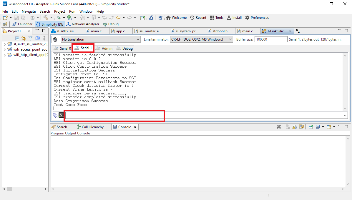
Console input can be entered and sent to the device.
Customize Application Components#
Simplicity Studio allows you to add or remove functional components in your application, such as BSD Sockets.
Note: For information about the functional components available with WiSeConnect SDK v3.x, see the Application Components section.
Add a Component#
In the Project Explorer pane, double-click the project_name.slcp file.
Select the SOFTWARE COMPONENTS tab.
Select the SDK Extensions filter.
Browse or search for and select the component that you want to install.
Click Install.
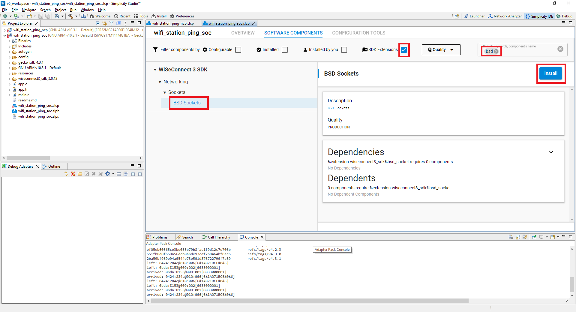
Note: Image is for illustration only. Component details shown may be outdated.
Studio will add the component and display a success message.
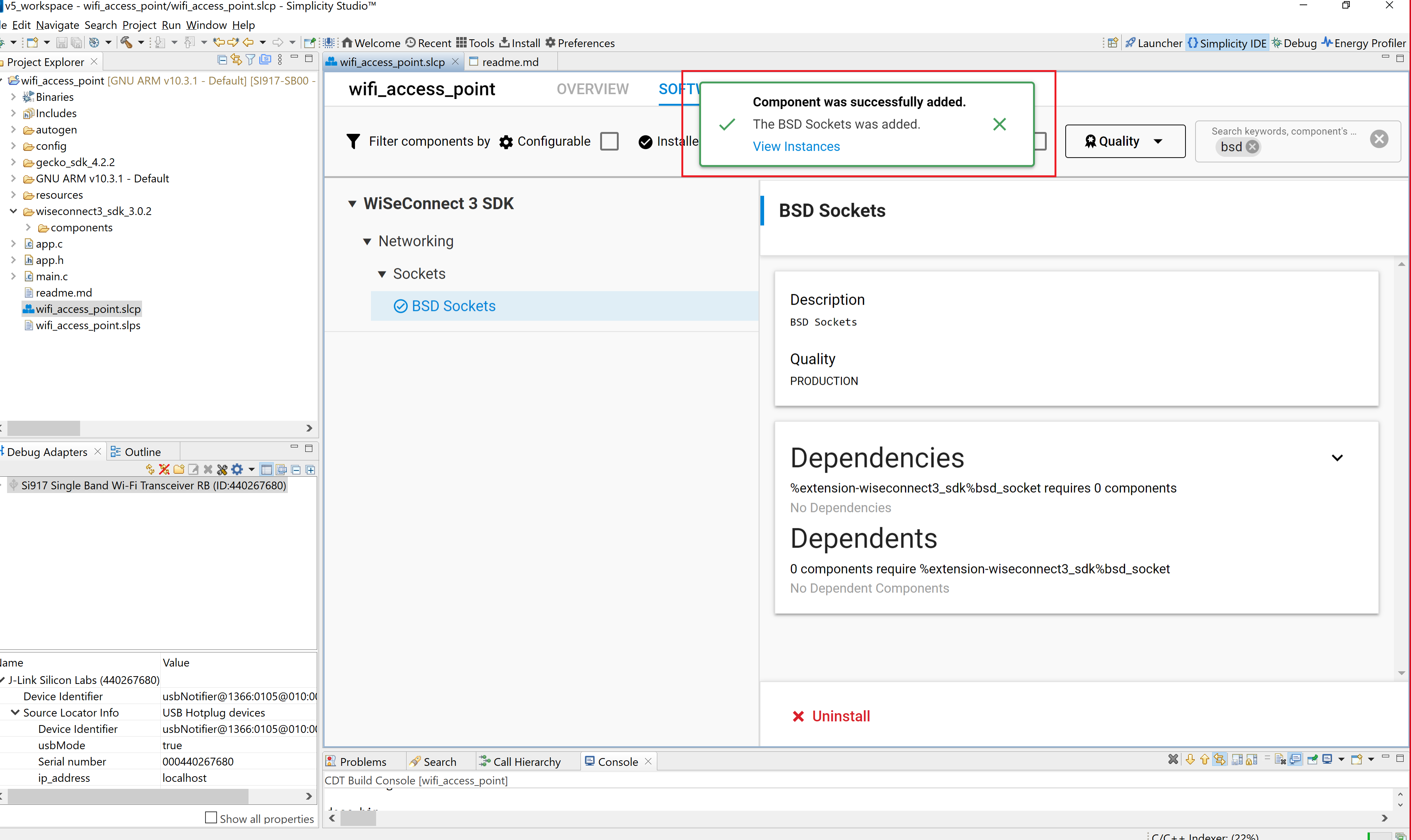
Note: Image is for illustration only. Component details shown may be outdated.
Note: You may use the Component Editor to configure a component after adding it or to configure other components in your example.
Remove a Component#
View the list of WiSeConnect 3 extension components by following steps 1-3 of the previous section.
Select the Installed filter to view the components you have installed.
Browse or search for and select the component you want to remove.
Select the component and click Uninstall.
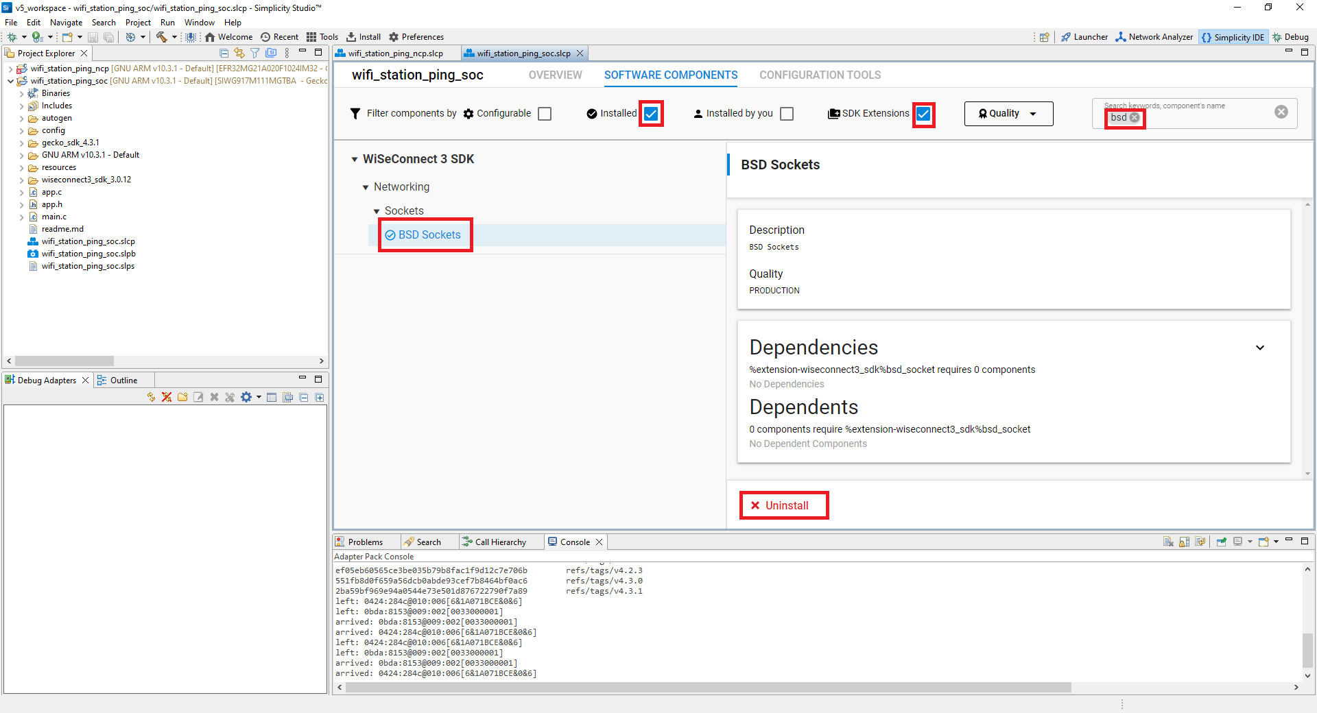
Note: Image is for illustration only. Component details shown may be outdated.