Hardware Configurations#
GPIO Pin Configurations#
The following table describes the GPIO pin connections between the EFR32MG21 Zigbee device and the SiWG917 Wi-Fi device, including the GRANT, REQUEST, PRIORITY, and EFR Tx signals.
Pin Description (BRD4002A) | EFR32 (BRD4002A) Pins | SiWG917 radio board GPIO Pins | SiW917 Evaluation Board |
|---|---|---|---|
REQUEST | Pin 7 | ULP_GPIO_1 | P16 |
PRIORITY | Pin 11 | ULP_GPIO_6 | I2C_SDA (Expansion Header 16) |
GRANT | Pin 9 | GPIO_7 | P20 |
EFR Tx | Pin 13 | NA | NA |
EFR32MG21 + SiWG917 Setup#
To configure PTA in Main and Secondary modes, use the setup shown in the following figure. This setup includes several key components.
The SiWG917 SoC radio board serves as the PTA Main and is mounted on the EFR32 baseboard, where PTA configurations are implemented.
The combined EFR32 + SiWG917 setup manages Wi-Fi communication as the PTA Main.
A Zigbee module functions as the PTA Secondary, handling Zigbee communication.
These modules are connected via the PTA 3-wire interface, which consists of the following signals:
Request: Asserted by the Zigbee module to request access to the communication channel.
Grant: Asserted by the SiWG917 (WLAN module) to grant access to the Zigbee module.
Priority: Indicates that the Zigbee device is requesting high-priority access to the 2.4 GHz band for transmission and reception (Tx/Rx).
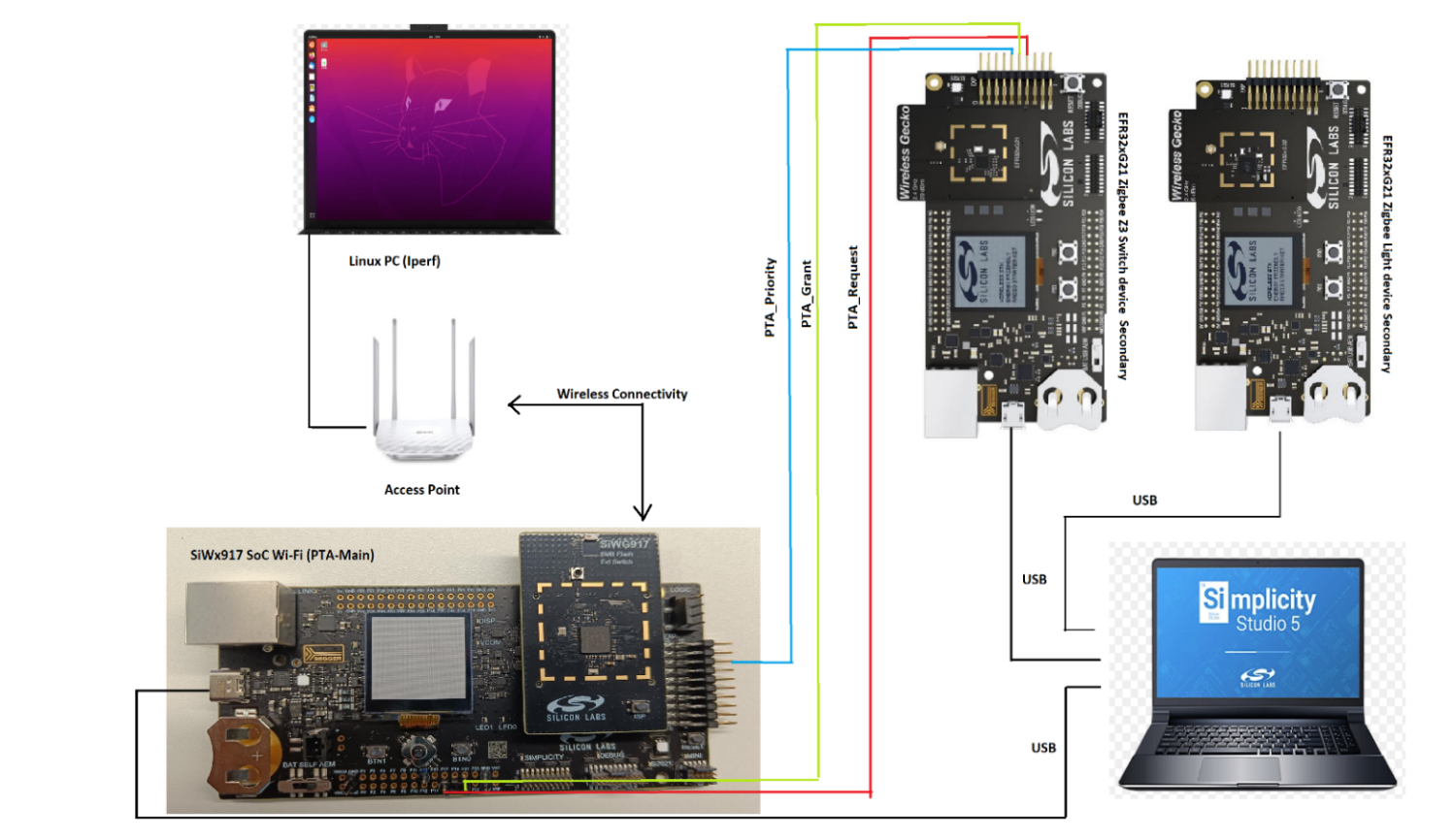
This setup enables PTA coordination, where the SiWG917 SoC manages arbitration between WLAN and Zigbee channels to minimize interference and optimize performance. It provides a reference for implementing coexistence and interference management between Wi-Fi and Zigbee in IoT environments, ensuring reliable and efficient communication.