Commander Command Line Interface (CLI) Operations#
This section describes common Commander Command Line Interface (CLI) operations for programming, managing, and maintaining SiWG917 devices.
Each subsection includes a short description, an example command, and key usage notes.
Notes:
For SiWG917Y Module Orderable Part Numbers (OPNs), include the
--serialnoparameter with all Commander CLI commands to specify the module’s serial number.For no in-package flash OPNs, use
--pinset [n], where n corresponds to the General Purpose Input/Output (GPIO) pinset to which the external flash is connected.
Pinset Configuration#
When using Commander with devices that have no in-package flash, you must specify the flash pin configuration using the --pinset [n] parameter.
Pinset No. (n) | GPIO Set | Description |
|---|---|---|
| GPIO 0–5 | Default setting for in-package flash or standard development boards. |
| GPIO 46–51 | Used for external flash connected via alternate GPIO lines. |
| GPIO 52–57 | Used for external flash on secondary or custom hardware interfaces. |
Tip: Incorrect pinset configuration may cause flash read or write failures.
Always confirm the flash-to-GPIO mapping for your board before using--pinset.
MBR Provision#
The Master Boot Record (MBR) defines configuration parameters such as flash mode and boot options.
Provisioning the MBR is typically the first step when setting up a new device.
Command#
commander mfg917 provision --mbr <filename.bin|default> -d <OPN> [--skipload] [--pinset n]Use
--mbr defaultto apply default configuration settings.Use
--pinset nif the device does not have in-package flash.Use the
--skiploadoption to skip loading the manufacturing firmware into device RAM. Normally, the Commander CLI automatically loads this firmware when the first command is issued to the device.
Note: Each time the device is powered on, ensure that the first command sent using the Commander CLI does not include the
--skiploadoption.
Example:
For SiWG917M111MGTBA to apply the default MBR configuration, use the following command:
commander mfg917 provision --mbr default -d SiWG917M111MGTBA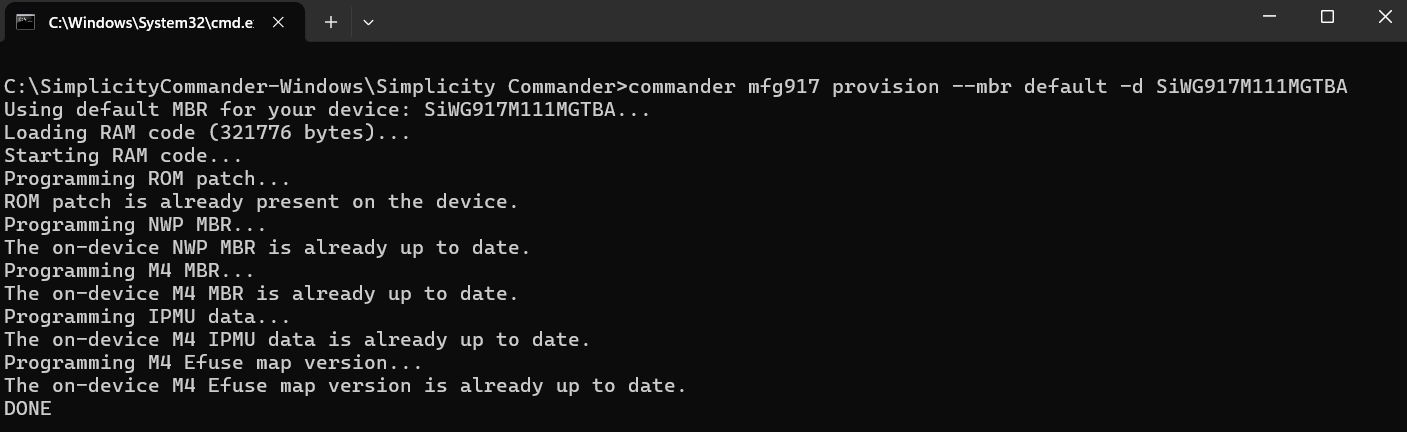
MBR Read#
Read the current Network Wireless Processor (NWP) and M4 MBR contents and save them to a file for verification or backup.
NWP MBR Read Command#
commander mfg917 read tambr --out tambr_backup.json -d <OPN>M4 MBR Read Command#
commander mfg917 read m4mbrcf --out m4mbrcf_backup.json -d <OPN>Example:
For SiWG917M111MGTBA to read NWP MBR configuration, use the following command:
commander mfg917 read tambr --out tambr_backup.json -d SiWG917M111MGTBA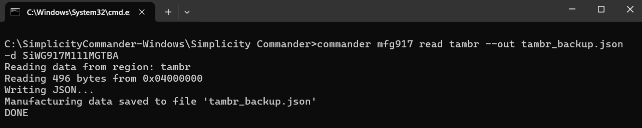
eFuse Read#
Read the eFuse contents and save them to a file for verification or backup.
eFuse Read Command#
commander mfg917 read efuse --out efuse_backup.json -d <OPN>Example:
For SiWG917M111MGTBA to read eFuse contents, use the following command:
commander mfg917 read efuse --out efuse_backup.json -d SiWG917M111MGTBANWP and M4 Firmware Load#
Load firmware images for both SiWG917 cores:
NWP: Handles connectivity and networking functions.
M4 Core: Executes user application logic.
Commands#
# Load NWP firmware
commander rps load nwp_fw.rps -d <OPN>
# Load M4 firmware
commander rps load app_fw.rps -d <OPN>Example:
For SiWG917M111MGTBA to load NWP and M4 firmware, use the following command:
# Load NWP firmware
commander rps load SiWG917-B.2.14.5.2.0.7.rps -d SiWG917M111MGTBA
# Load M4 firmware
commander rps load out_of_box_demo.rps -d SiWG917M111MGTBA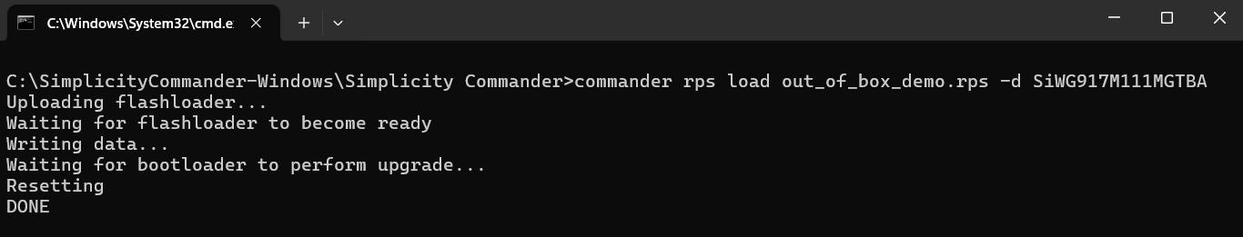
Combine NWP and M4#
Generate a single combined RPS image that merges both NWP and M4 firmware images.
This operation is commonly used for XiP (Execute in Place) configurations and for creating secure production images.
Combine NWP and M4 Conversion and Loading Steps#
Step | Description | Security | Command (Syntax) |
|---|---|---|---|
1 | NWP Image with Combined Flag | Disabled |
|
Enabled |
| ||
2 | M4 Image with Combined Flag | Disabled |
|
Enabled |
| ||
3 | Combine NWP and M4 Images | Disabled |
|
Enabled |
| ||
4 | Load the Combined Image | — | Load the combined image using the Over-the- Air (OTA) process only. Refer to the HTTP OTAF example for detailed instructions. |
Example:
For SiWG917M111MGTBA to combine NWP and M4 firmware images, use the following command:
# NWP Image with Combined Flag - Security is disabled
commander rps convert nwp_image_combinedflag.rps --taapp SiWG917-B.2.14.5.2.0.7.rps --combinedimage
# M4 Image with Combined Flag - Security is disabled
commander rps convert m4_image_combinedflag.rps --app out_of_box_demo.rps --combinedimage
# Combine NWP and M4 Images - Security is disabled
commander rps convert combined_image.rps --app m4_image_combinedflag.rps --taapp nwp_image_combinedflag.rps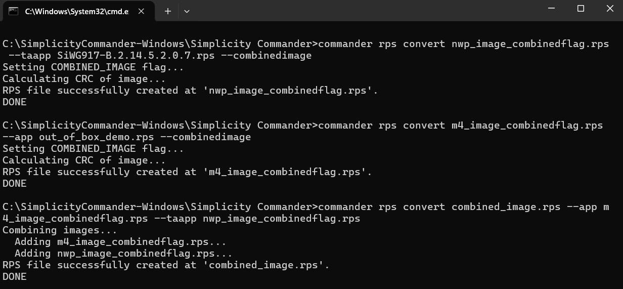
Flash Dump#
Extract the full flash memory contents into a binary file.
This is useful for debugging or creating a firmware backup.
Command#
Use
--pinset nif the device does not have in-package flash.
Example:
For SiWG917M111XGTBA to extract a full flash memory dump, use the following command:
commander mfg917 dump flashdump.zip -d SiWG917M11XMBTGA --pinset 2Flash Erase#
Erase flash memory either completely or by specific regions as needed.
Command#
# Erase entire flash
commander device masserase -d <OPN> [--pinset n]
# Erase only the userdata region
commander mfg917 erase userdata -d <OPN> [--pinset n]Use
--pinset nif the device does not have in-package flash.
Note: Erasing flash permanently deletes firmware, configuration data, and user content.
Example:
For SiWG917M111MGTBA to erase entire flash and user data, use the following commands:
# Erase entire flash
commander device masserase -d SiWG917M111MGTBA
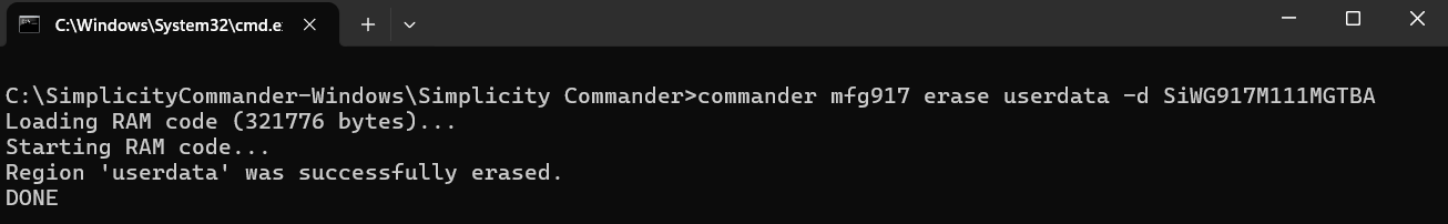
# Erase only the userdata region
commander mfg917 erase userdata -d SiWG917M111MGTBA 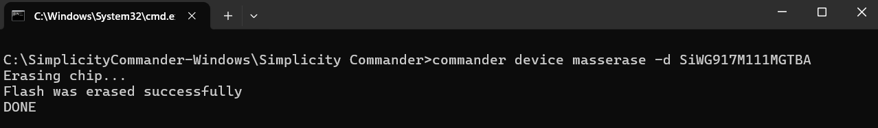
Device Reset#
Perform a soft reset on the SiWG917 device.
Command#
commander device reset -d <OPN>Example: For SiWG917M111MGTBA to reset the device, use the following command:
commander device reset -d SiWG917M111MGTBA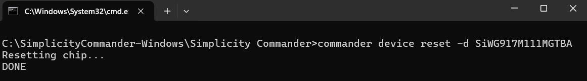
Read Memory Region#
Read data from a specific memory range.
Command#
commander mfg917 read --range (address):+(number of bytes) -d <OPN>Example: For SiWG917M111MGTBA to read a memory region, use the following command:
commander mfg917 read --range 0x04201000:+120 -d SiWG917M111MGTBA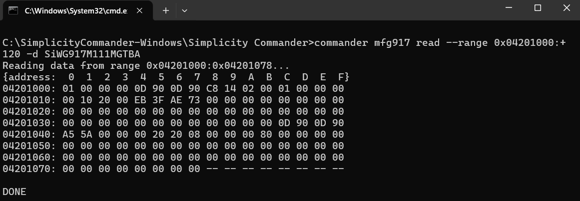
User-Space Operations#
The user data space for the M4 core is located at the following memory range:
Start Address:
0x047F7000End Address:
0x047FBFFF
You can use the following Commander CLI commands to write and read user data in this region.
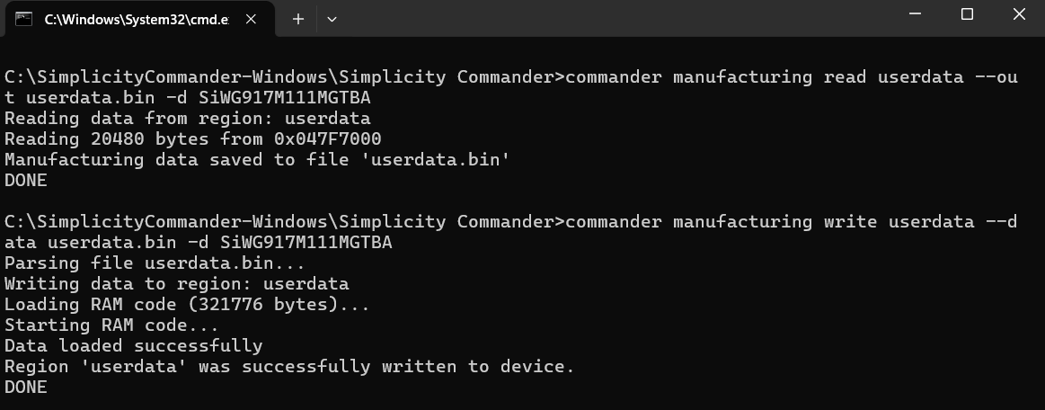
Read User Data#
commander manufacturing read userdata --out userdata.bin -d <OPN> [--pinset 2]Write User Data#
commander manufacturing write userdata --data userdata.bin -d <OPN> [--pinset 2]Example: For SiWG917M111MGTBA to read and write user data, use the following commands:
# Read User Data
commander manufacturing read userdata --out userdata.bin -d SiWG917M111MGTBA
# Write User Data
commander manufacturing write userdata --data userdata.bin -d SiWG917M111MGTBA