Connect the SiWG917 Device#
Supported Hardware and Interfaces#
Hardware Options#
SiWG917 Development Kits: Recommended for evaluation and prototyping.
Custom Boards: Supported if Serial Wire Debug (SWD)/Joint Test Action Group (JTAG) and power connections are properly configured.
Supported Interfaces#
SEGGER J-Link debugger (SWD/JTAG)
Required Drivers#
Install the following drivers before connecting the device:
Note: You do not need to install any drivers. The required drivers are preinstalled when you download the Simplicity Commander Command Line Interface (CLI).
SEGGER J-Link drivers — required for SWD/JTAG communication
libusb (Linux/macOS) — required for USB communication on non-Windows platforms
Note: You may need administrative or
sudoprivileges to install these drivers.
Physical Connection Setup#
Follow these steps to connect the SiWG917 device:
If you are using a custom board (skip for the evaluation kit), connect the J-Link debugger to the SWD/JTAG pins on the SiWG917.
Connect the board to your host PC using a USB cable.
Power on the board.
Verify that the power LED and other status indicators are active.
Tip: Always confirm correct pin alignment when connecting J-Link to avoid damage.
Detecting Connected Devices#
After connecting the hardware, verify that the Commander CLI detects your device.
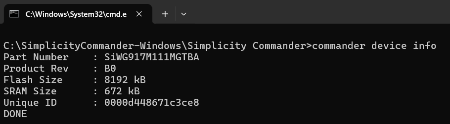
Run the following command:
commander device infoExpected Output: If the device is detected successfully, the system displays information such as serial number, device type, and memory details.
Note: For more details on Command Line Syntax and General Options used with Simplicity Commander, see the official documentation: Simplicity Commander General Information
Common Troubleshooting Tips#
If you encounter issues while connecting or operating the SiWG917 device, refer to the table below for common causes and recommended actions.
Issue | Possible Cause | Recommended Action |
|---|---|---|
Device not detected | Missing drivers, incorrect cabling, or no power | Verify driver installation, check cable connections, and ensure the board is powered on. |
USB connection issue | Driver or permission error | Reinstall USB drivers or adjust user permissions ( |
Flash operation fails | Incorrect command sequence or skipped firmware load | Do not use |
Tip: Always verify physical connections and power indicators before performing software troubleshooting.
Manufacturing Utility Commands – Parameters#
The following table lists the parameters used by manufacturing utility commands in the Simplicity Commander CLI.
These parameters are referenced throughout subsequent sections and are essential for performing provisioning, configuration, and calibration tasks on SiWG917 devices.
Parameter Descriptions#
Field | Description |
|---|---|
provision | Writes TA Master Boot Record (MBR), M4 MBR, and reads/writes M4 IPMU in common flash mode. |
write | Compares the provided MBR file with the one on the device and writes only the new changes to the MBR. |
read | Reads the contents of the specified region or file. |
init | Generates the activation code for device provisioning. |
--mbr | Specifies the MBR file. |
--keys | Defines security or encryption keys to be used during provisioning. |
m4mbrcf | Common flash M4 MBR configuration. |
m4mbrdf | Dual flash M4 MBR configuration. |
m4ipmucf | M4 IPMU data for common flash configuration. |
m4ipmudf | M4 IPMU data for dual flash configuration. |
efusecopy | Updates eFuse data to flash for the selected region. |
<full opn> | Specifies the full Ordering Part Number (OPN) of the device. Example: |
<updated-mbr-fields.json> | JSON file containing updated MBR fields, such as security level configuration. |
-d <Device> | Specifies the target device for Commander operations. |
--skipload | Skips loading the manufacturing firmware (normally loaded into device RAM during the first CLI command). Use only after the first firmware load. |
Note: The first command given to the device after power-on must not use
--skipload. Always allow Commander to load the manufacturing firmware into RAM on initial connection.
Pinset Configuration#
When using Commander with devices that have no in-package flash, you must specify the flash pin configuration using the --pinset [n] parameter.
Pinset No. (n) | GPIO Set | Description |
|---|---|---|
| GPIO 0–5 | Default setting for in-package flash or standard development boards. |
| GPIO 46–51 | Used for external flash connected via alternate GPIO lines. |
| GPIO 52–57 | Used for external flash on secondary or custom hardware interfaces. |
Tip: Incorrect pinset configuration may cause flash read or write failures.
Always confirm the flash-to-GPIO mapping for your board before using--pinset.
Radio Transmission Parameters#
Parameter | Description |
|---|---|
--stop | Turns off radio transmission. |
--noburst | Enables continuous transmission instead of burst mode. |
--internalant | Selects the virtual internal RF switch. By default, the external antenna RF switch is selected. |
--ctuneoverride | Writes the XO CTUNE value directly into flash, replacing the existing frequency offset. |
--store | Stores computed calibration values in flash memory. |
--storeinefuse | Stores computed calibration values in the device’s eFuse memory. |