Z-Ware Portal Installation and Use of Web Portal#
This lab exercise explores how to set up and use the Z-Ware reference portal design. It is the fifth exercise in the ‘Z-Wave controller training course’ series. In the course of the exercise, you will learn how to do the following:
Installing Z-Ware portal
Connecting to Z/IP Gateway
Including and removing nodes
Controlling devices
Setting up scenes
Doing Smart Start inclusion
Introduction#
In this lab exercise, the Z-Ware portal is installed and the features of the the Web portal are explored.
Hardware Requirements#
2 UZB Controllers
1 Raspberry 3B (+)
1 SD card
1 IP Router with built in DHCP
1 WSTK Main Development Board
1 Z-Wave Radio Development Board: ZGM130S SiP Module
1 USB Zniffer
Software Requirements#
VNC and optionally SSH client https://www.realvnc.com/en/connect/download/viewer/ https://www.chiark.greenend.org.uk/~sgtatham/putty/latest.html
Simplicity Studio v4
Z-Wave 7 SDK
Z-Wave PC Controller
Z-Wave Zniffer
Prerequisites#
Familiarize yourself with the protocol by referring to the following materials:
https://www.silabs.com/support/training/z-wave-700-series
Videos 1-3 and
exercise 6,7 and 10 will be relevant.
Further the participant should have completed
Controller training session 1
Controller training lab exercise 1
Controller training session 2
Controller training lab exercise 2
Controller training session 3
Controller training lab exercise 3
Controller training session 4
Controller training lab exercise 4
Controller training session 5
You should also be familiar with connecting to the Raspberry Pi.
Installing Z-Ware#
The Z-Ware binaries was transferred to the Raspberry Pi as part of Basic Z/IP Gateway Lab
First, unpack the Z-Ware binaries:
$ tar -zxvf zwarelocal-rpi.tar.gzEnter the folder:
$ cd zwarelocal-rpi/Run the install script:
$ ./install.sh --configure-rpi /home/pi/zwarelocal/Leave all parameters at their default, and press enter at each prompt to continue. When the installation has completed, restart the Raspberry Pi.
First Connection to Z-Ware#
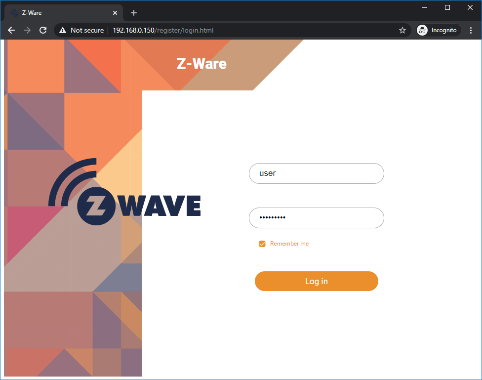
Enter the IP or URL of the Raspberry Pi in the address bar of a browser. Ignore the certificate error (in Chrome, click “Advanced” and “Proceed to address” When prompted for username and password enter “user” and “smarthome”:
Connecting Z-Ware to Z/IP Gateway#
If Z-Ware is not connected to Z/IP Gateway, a spinning wheel will be shown on the home screen. To verify the connection, select “Settings” on the left-hand bar:
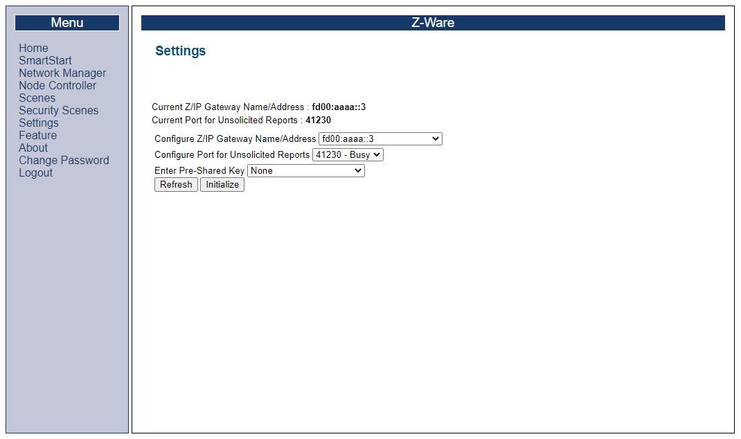
If “Current Z/IP Gateway Name/Address” and “Current Port for Unsolicited Reports” are both populated, Z-Ware is correctly connected to Z/IP Gateway.
If this is not the case, a connection can be achieved by selecting the gateway from the “Configure Z/IP Gateway Name/Address” drop down, setting “Configure Port for Unsolicited Reports” to 41230, “Enter Pre-Shared Key” to “Select Pre-Shared Key...” and set the key to “123456789012345678901234567890AA”. Finally, click “Initialize”
Including Nodes#
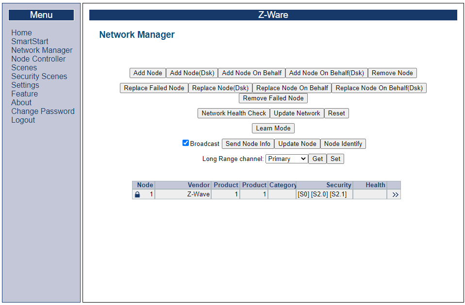
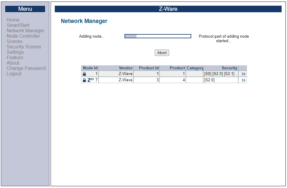
Start out with a WSTK board programmed with the Switch on/off sample application. On the left-hand pane in the UI, select “Network manager” and “Add Node”
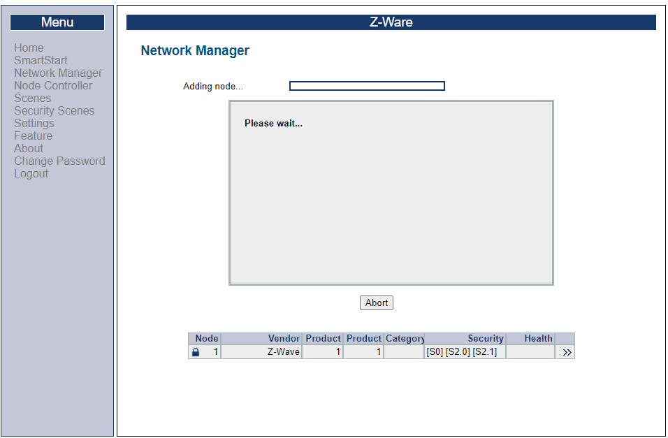
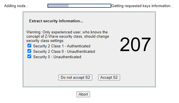
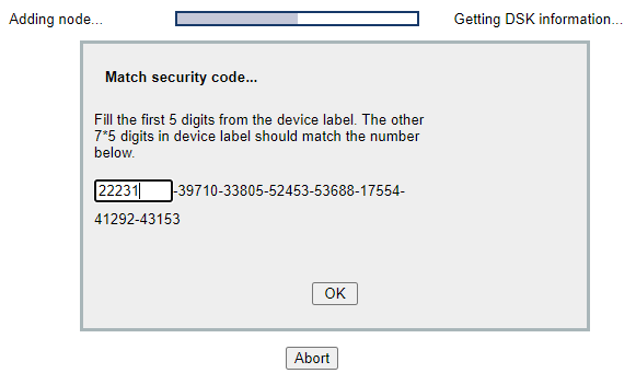
When prompted click “Accept S2” to accept security request, and enter the S2 DSK.
Wait for the inclusion to finalize
Other Network Management Operations#
Select “Network Manager” -> “MAINTENANCE”
Here, general network management operations are available, such as remove devices or resetting the Z-Wave network entirely.
Controlling Devices#
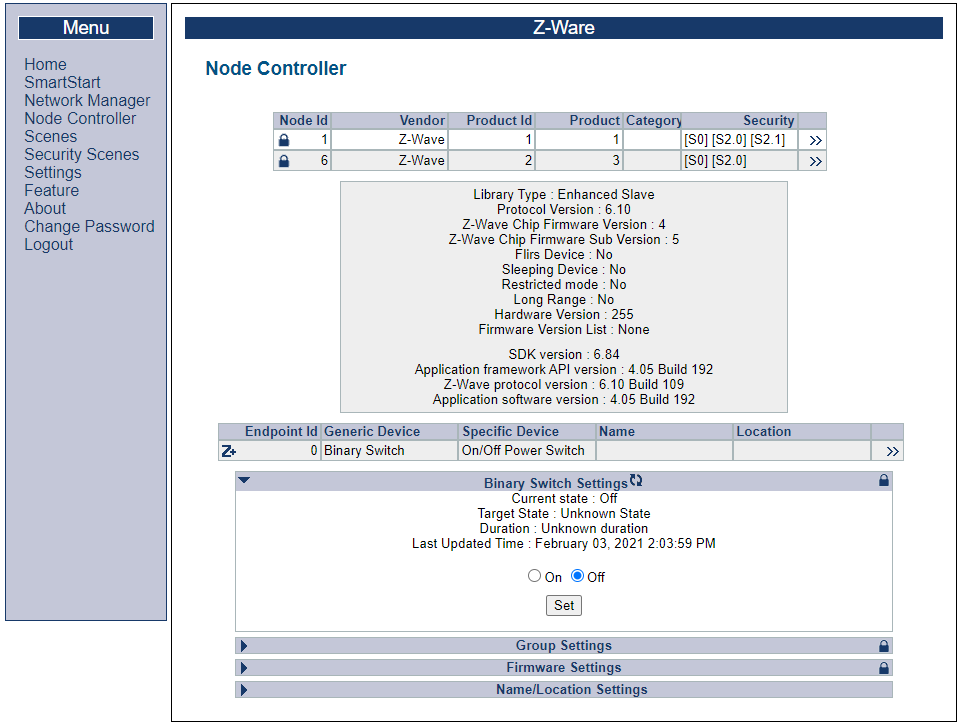
On the left-hand pane, under “Node Controller”, Click “>>” next to node 6, the newly included switch On/off, and control it by expanding “Binary Switch Settings” and toggle the state between “On” and “Off”.
Creating Scenes#
In this exercise, the control of device 6 is automated.
Include a new WSTK board programmed with the Sensor PIR sample application. Check that both switch and sensor devices are listed in the left-hand pane.
Next, Click “Scenes” and select “+ Add New Scene” to create a new scene. Give the scene an appropriate name, e.g., “Lights on when motion detected”.
Configure an Action#
Next, add an action: Under “Action” select the switch device, most likely “Node 6”, and select the endpoint and interface type from the drop down. Make sure “on” is highlighted. Click “Add”.
Configuring a Trigger#
Under “Events, select the sensor device, most likely “Node 7”, and select the endpoint and interface type from the drop down. Select the “Event” “Motion Detection, Unknown Location”. Click “Add”.
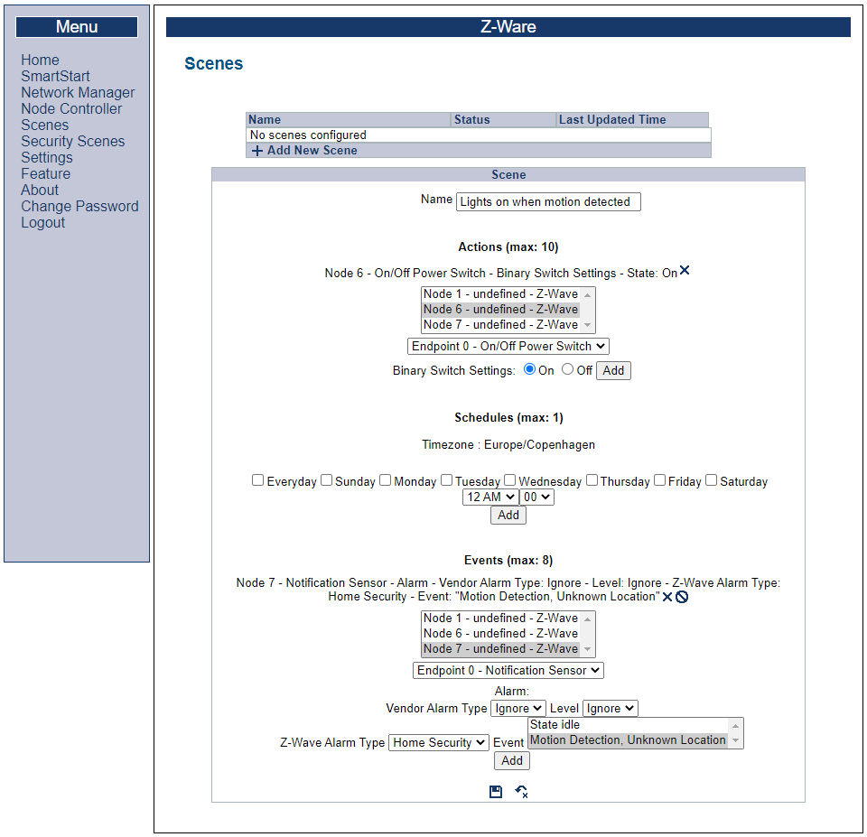
Finally, click the floppy icon to save.
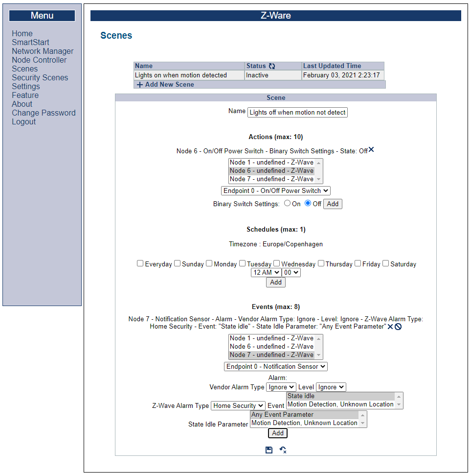
Configuring the opposite Scene#
Because the Sensor PIR both sends “motion detected” and state “idle”, create an additional scene which turns the light off when motion is no longer detected:
Testing the Scene#
Press BTN2 on the Sensor device for a short while. This results in LED0 lighting up on the switch device for 5 seconds and then being turned of again.
Smart Start Inclusion#
First exclude the Switch on/off from the network, to allow it to be included again. To add a WSTK based sample app using smart start, make sure it is connected to Simplicity Studio. Select the board the “Simplicity Launcher” view, right click it and click “device options”. Under device options, click “Z-Wave device settings”:
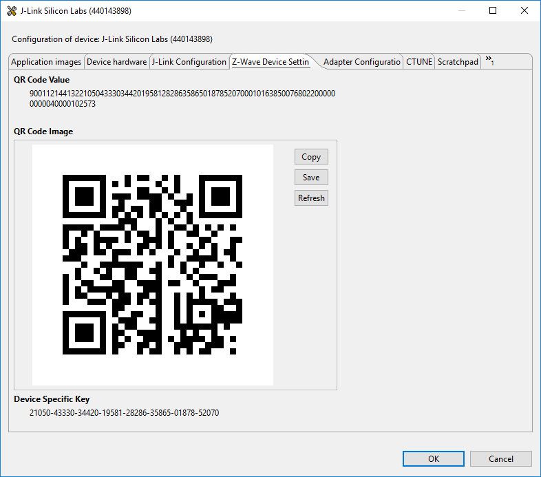
In Z-Ware select “SmartStart”, “Add Device”. Enter the DSK found in Simplicity Studio, name the device and click “Save”.
After a short wait, the provisioned the device will change state to "including" in the provisioning:
Conclusion#
At this point, you should be familiar with the Z-Ware UI and it’s capabilities.