Setting up a Client#
This section describes how to set up an OTA client with the following configurations:
Using internal flash to store the OTA image.
Using specific addressing.
Using the internal flash bootloader.
EFR32MG24-based development kit (see the UG526: EFR32xG24 2.4 GHz 20 dBm Radio Board User's Guide for details about how to configure the Wireless Pro Kit (WPK) development board for use with the EFR32MG24).
At a high level, the client set up contains the following steps:
ZAP Configuration
Install Required Components
Component Configuration
Flash the Client
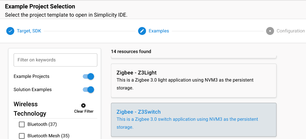
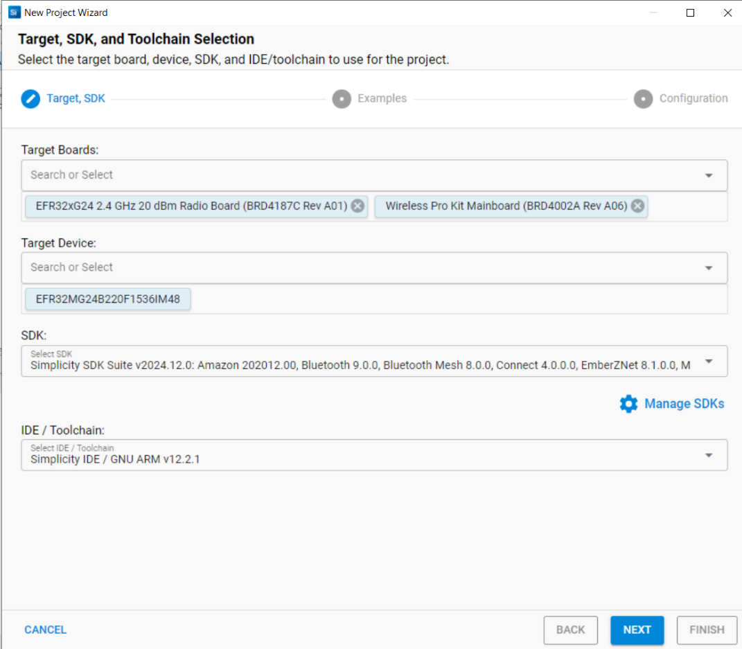
As a base, use the Zigbee - Z3Switch SoC sample application. To create this sample application, begin by opening Simplicity Studio v5. Click File > New > Silicon Labs Project Wizard. Then select the appropriate device, board, compiler, and stack. The image below shows the sample application. Select it and give it a name. For this document, the client is named "ZNet_OTA_Client_7".
1. ZAP Configuration#
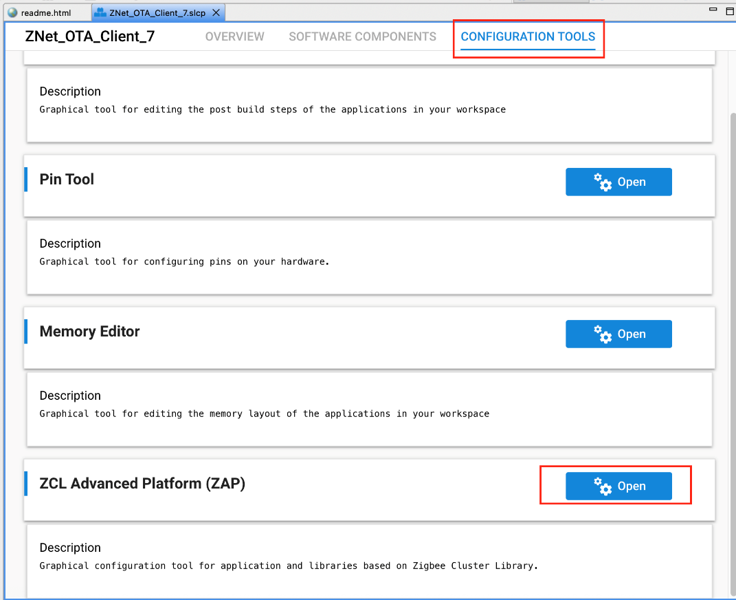
The first step in the OTA process is to enable the OTA cluster on the client's project. This adds all necessary OTA attributes and commands required for transferring the image from the server to the client. To begin, open the ZAP tool by launching your project file (*.slcp), navigating to the Configuration Tools tab, and selecting ZAP.
The next step is to enable the Over the Air Bootloading cluster as a client. First select endpoint number 1, and enable client for the cluster by checking the checkbox.
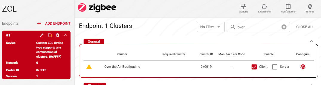
For more information, such as what commands and attributes have been enabled by default, click Configure.
2. Install Required Components#
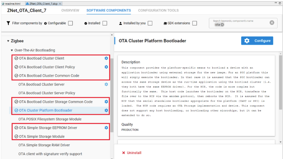
After the OTA ZCL Cluster is enabled, which enables the correct Zigbee messages (e.g., image query and next block request) to be sent and received, processing of those messages needs to be enabled. This is done by enabling the correct components. The diagram below shows the components used in this example and their dependencies. The yellow components handle the cluster. The green components are related to storing the OTA image in non-volatile memory.
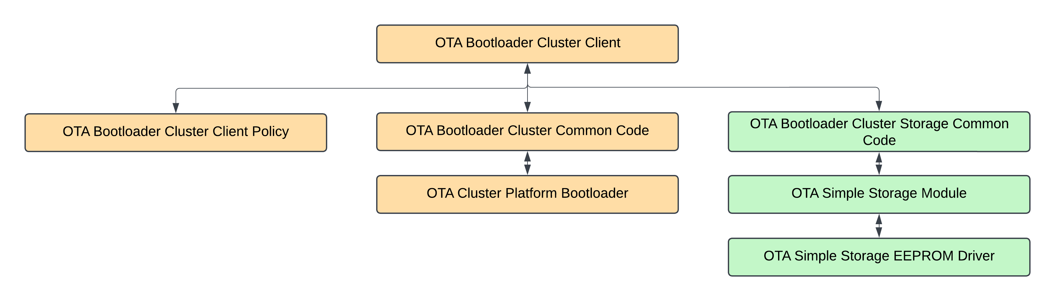
Each component is briefly described below to give an impression of what the functionality is. All of these components need to be enabled for the client to work properly and store the OTA image in the internal flash.
Component Name | Description |
|---|---|
OTA Bootload Cluster Client | Implementation of the Zigbee Over-the-air Bootloading Client Cluster. This implementation finds the OTA server in the network, periodically queries the server for a new image to download, downloads the data, and then waits for the server command to tell it to upgrade. Optionally it can cryptographically verify the image before upgrade. |
OTA Bootload Cluster Client Policy | This implementation shows how to define the policies of the Zigbee Over-the-air bootloader cluster client. It allows the implementor to decide what manufacturer ID, image type ID, and file version information is used when querying the server. It also defines callbacks, such as download complete and ready to bootloading. |
OTA Bootload Cluster Common Code | Common code for Silicon Labs implementation of the Zigbee Over-the-air Bootloading Cluster Client and Server components. |
OTA Cluster Platform Bootload | This component provides the platform-specific means to bootload a device with an application bootloader using external storage for the new image. For an SOC platform this will simply execute the bootloader. In that case it is assumed that the SOC bootloader can access the same storage device as the run-time application using the bootload cluster (i.e. they both have the same EEPROM driver). For the NCP, the code is more complex but functionally the same. This host code launches the bootloader on the NCP, transfers the file over to the NCP via the xmodem protocol, then reboots the NCP. It is assumed for the NCP that the serial standalone bootloader appropriate for the platform (UART or SPI) is loaded. The NCP code requires an OTA Storage implementation and device. This component does not support any host bootloading, or bootloading other microchips, but it can be extended to do so. |
OTA Bootload Cluster Storage Common Code | Common code for any storage module implementing an Over-the-air bootloading cluster. This is used by either the Zigbee or legacy Standalone bootloader implementations. |
OTA Simple Storage Driver Module | This is a simple Over-the-air bootloading cluster storage module that stores only ONE file in the storage device (for use by the client or server component). It requires a storage driver. Silicon Labs provides two, an EEPROM version and a RAM version. |
OTA Simple Storage EEPROM Driver | This is a driver for the Over-the-air simple storage module component. It uses an EEPROM as the underlying storage device. It provides a means to record data being read or written, as well as metadata with information about how far along a client download is. It can be used either by an OTA Client or an OTA Server. Note that this component assumes that the flash storage does not have read-modify-write support. Users should ensure this value matches the flash storage device used by the application. A mismatch between the project-configured value and the actual flash storage support value will result in an application that asserts upon startup. |
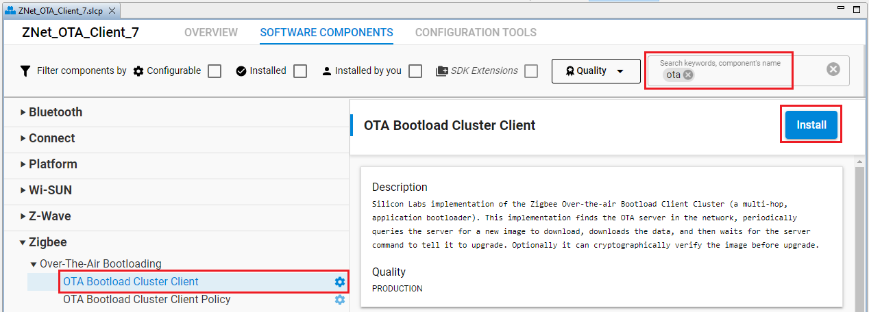
Components can be installed by searching for 'OTA' in the search bar. Select them and click on the install button as shown in the figure below.
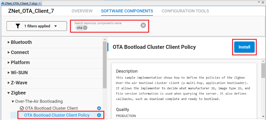
The following components should be added to the OTA client's project:
Note: Installing one component may pull in other required components due to dependencies. Please ensure all required components are installed before moving to the next section. If you get any pop-ups or have questions about configurations, reference the details below for more information.
3. Component Configuration#
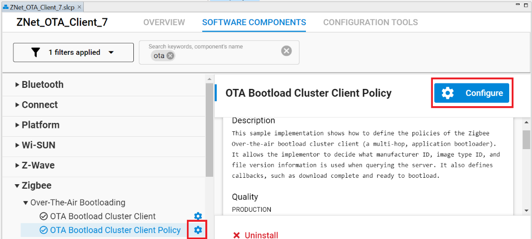
This section describes the configuration for each of the mandatory components. You can configure the component by searching for the component name, select the component, and click on the configuration button, as show in the figure below.
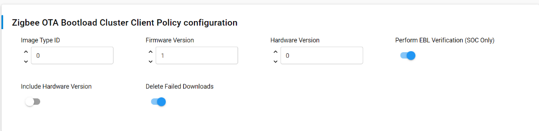
OTA Bootloader Cluster Client Policy
Configure the OTA Bootloader Cluster Client Policy as shown in the figure below. The following table describes each configuration parameter briefly.
| Parameter | Default Value | Description |
|---|---|---|
| Image Type ID | 0 | This is the device's OTA image identifier used for querying the OTA server about the next image to use for an upgrade. When the OTA client queries the server for updates, it includes this Image Type ID in its request. This allows the server to determine if it has a compatible update for the specific device type. |
| Firmware Version | 1 | When the OTA client queries the server for updates, it includes this firmware version in its request. The server uses this information to determine if a newer firmware version is available for the device. When creating a new firmware image for OTA updates, you should increment this version number. |
| Hardware version | 0 | Hardware Version is the hardware version of the device. It's used to determine if a particular OTA image is compatible with the device's hardware. OTA Images may be configured with minimum and maximum hardware versions that they are supported on. If set to 0xFFFF (65535), it indicates that the device is not restricted by hardware version. |
| Preform GBL verification | enabled |
This option is only applicable to SOC (System-on-Chip) devices, not for NCP (Network Co-Processor) setups. If enabled, the OTA client will perform GBL (bootloader) verification during the OTA update process. After the signature verification passes, the device will use the application bootloader routines to verify the GBL image. The update process may take slightly longer due to this additional verification step. If disabled, the OTA client will not perform the additional GBL verification step. The device will rely solely on the signature verification process to validate the OTA image. |
| Include hardware Version | disabled |
If enabled, the OTA client will include the current hardware version of the device in messages sent to the OTA server. This allows the server to consider the device's hardware compatibility when offering firmware updates. This is useful for managing updates across different hardware revisions of the same product. If disabled, the OTA client will not include the hardware version information in messages to the OTA server. The server will not have explicit information about the device's hardware version when considering updates. |
| Delete Failed Downloads | enabled |
If enabled, the OTA client will delete any image (partial or complete) that has been downloaded but failed verification. It will also delete the image if the server instructs the client to abort the download or upgrade process. This helps conserve storage space and ensures that only valid and approved firmware images are kept on the device. If disabled, the OTA client will retain failed or aborted download images on the device. This might be useful for debugging purposes or if there's a need to analyze failed updates. However, it may consume more storage space on the device over time. |
OTA Bootloader Cluster Client
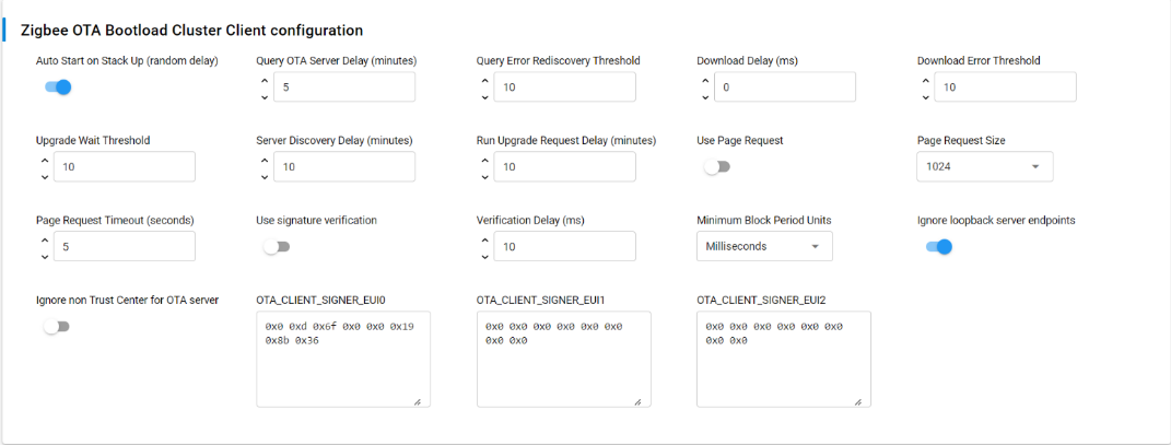
Configure the OTA Bootloader Cluster Client as the picture below. The table below the picture describes each configuration parameter briefly.
| Parameter | Default Value | Description |
|---|---|---|
| Auto Start on Stack Up (Random Delay) | Enabled |
If enabled, the OTA Client will automatically start when the Zigbee stack starts up, with a random delay of up to 5 minutes. This delay is implemented to avoid an issue where multiple devices in the network all query the server simultaneously after a power-outage. If disabled, the OTA Client won't automatically start. |
| Query OTA Server Delay (minutes) | 5 | Query OTA Server Delay determines how often the OTA client queries the OTA server for a new upgrade image. |
| Query Error Rediscovery Threshold | 10 | Query Error Rediscovery Threshold determines the maximum number of sequential query errors before the client initiates a rediscovery of the OTA server. |
| Download Delay (ms) | 0 |
Download Delay determines how often a new block of data (or page) is requested during a download by the client. A value of 0 means the client will request the blocks (or pages) as fast as the server responds. |
| Download Error Threshold | 10 | Download Error Threshold determines the maximum number of sequential errors when downloading that will trigger the OTA client to abort the download. |
| Upgrade Wait Threshold | 10 | Upgrade Wait Threshold determines the maximum number of sequential, missed responses to an upgrade end request that will cause the OTA client to apply the downloaded upgrade anyway, even without explicit permission from the server. |
| Server Discovery Delay (minutes) | 10 | Server Discovery Delay determines how often a client will look for an OTA server in the network when it did not successfully discover one. Once a client discovers the server, it will remember that server until it reboots, or until the Query Error Rediscovery Threshold is hit. |
| Run Upgrade Request Delay (minutes) | 10 | Run Upgrade Request Delay determines how often the OTA client will ask the server to apply a previously downloaded upgrade when the server has previously told the client to wait. |
| Use Page Request | disabled |
If enabled, the client device uses an OTA Page Request command to ask for a large block of data all at once. If disabled, the client device uses individual image block requests for each block of data. |
| Page Request Size | 1024 | Page Request Size determines the size of the page to request from the server when using the OTA Page Request feature. |
| Page Request Timeout (seconds) | 10 | Page Request Timeout determines the length of time to wait for all blocks from a page request to come in. After this time has expired, missed packets will be requested individually with image block requests. |
| Use signature verification | Disable |
If enabled, all received OTA images must be signed with an ECDSA (Elliptic Curve Digital Signature Algorithm) signature. The client verifies the signature once the download has completed, before applying the update. If disabled, the OTA client does not perform signature verification on received images. Images are accepted and processed without checking for an ECDSA signature. |
| Verification Delay (ms) | 10 |
Verification Delay defines how often an ongoing verification process executes. When Signature verification is enabled this will control how often digest calculation is executed. Digest calculation can take quite a long time for an OTA image. Other processing for the system may be deemed more important and therefore we add delays between calculations. This also controls how often custom verification written by the application developer is executed. A value of 0 means the calculations run to completion without any delays. |
| Minimum Block Period Units | Milliseconds |
Minimum Block Period Units defines how the OTA client interprets the Minimum Block Period field in ImageBlockRequest and ImageBlockResponse messages during OTA updates. It has three possible settings:
The Minimum Block Period is used to control the rate at which the client requests blocks of data during an OTA update process. This helps manage network traffic and prevents the client from overwhelming the server with too many requests in a short time. |
| Ignore loopback server endpoints | Enabled |
If enabled, the OTA client will ignore any OTA server endpoints that are on the same device (loopback messages). It will only consider remote OTA servers during the server discovery process. This allows the client to discover and use OTA servers on other devices in the network. The first remote server to respond will be the one the client uses for OTA updates. If disabled, the OTA client will consider all OTA server endpoints, including those on the same device. The client might not discover remote OTA servers if a local server endpoint responds first. |
| Ignore non Trust Center for OTA server | Disabled |
If enabled, the OTA client will only consider the Trust Center as a valid OTA server. This restricts OTA updates to come only from the Trust Center, which is typically the most secure device in the network. If disabled, the OTA client will consider all OTA servers in the network, regardless of whether they are the Trust Center or not. This allows the client to use any available OTA server for updates. |
| OTA_CLIENT_SIGNER_EUI0 | {0x00, 0x0D, 0x6F, 0x00, 0x00, 0x19, 0x8B, 0x36} |
OTA_CLIENT_SIGNER_EUI defines the EUI64 (Extended Unique Identifier, 64-bit) of an authorized signer for OTA images. The EUI64, represented as an array of 8 bytes (uint8_t), is used to verify the authenticity of downloaded OTA images. The OTA client will check if the signer of a received image matches this authorized EUI64 before accepting and installing the update. OTA_CLIENT_SIGNER_EUI0 is the primary or default authorized signer EUI64. The default value is the EUI64 of the test certificate embedded within the image-builder tool provided by Silicon Labs. Using this default will allow customers to test image signing and verification prior to obtaining production signing certificates from Certicom. For production devices, you should use your own certificates and corresponding EUIs to ensure the security of your OTA update process.>/p |
| OTA_CLIENT_SIGNER_EUI1 | {0x00, 0x00, 0x00, 0x00, 0x00, 0x00, 0x00, 0x00} |
It sets the second authorized signer EUI64 for the OTA client. The default value provided (all zeros) is effectively a null or invalid EUI64 and will be ignored. In a production environment, you would replace this with your own authorized signer's EUI64 if you want to use multiple signers. |
| OTA_CLIENT_SIGNER_EUI2 | {0x00, 0x00, 0x00, 0x00, 0x00, 0x00, 0x00, 0x00} |
It sets the second authorized signer EUI64 for the OTA client. The default value provided (all zeros) is effectively a null or invalid EUI64 and will be ignored. In a production environment, you would replace this with your own authorized signer's EUI64 if you want to use multiple signers. |
OTA Bootloader Cluster Client Setup with Component Editor#
The steps to set up a sample OTA Bootloader Cluster Client with simply storage (on-chip) using Component Editor are described below.
On the SOFTWARE COMPONENTS tab, search for ota in the component's name search field (at the top right).
Under Zigbee > Over-The-Air Bootloading components, select the OTA Bootload Cluster Client component, and click Install as shown in the following figure.
In the pop-up window that appears, select and install the OTA Simple Storage Module. This component offers a simple and easy-to-understand storage solution, particularly for those who are new to OTA updates in Zigbee. By installing this module, the following components will also be installed:
OTA Bootload Cluster Common Code
OTA Bootload Cluster Storage Common Code
OTA Simple Storage EEPROM Driver
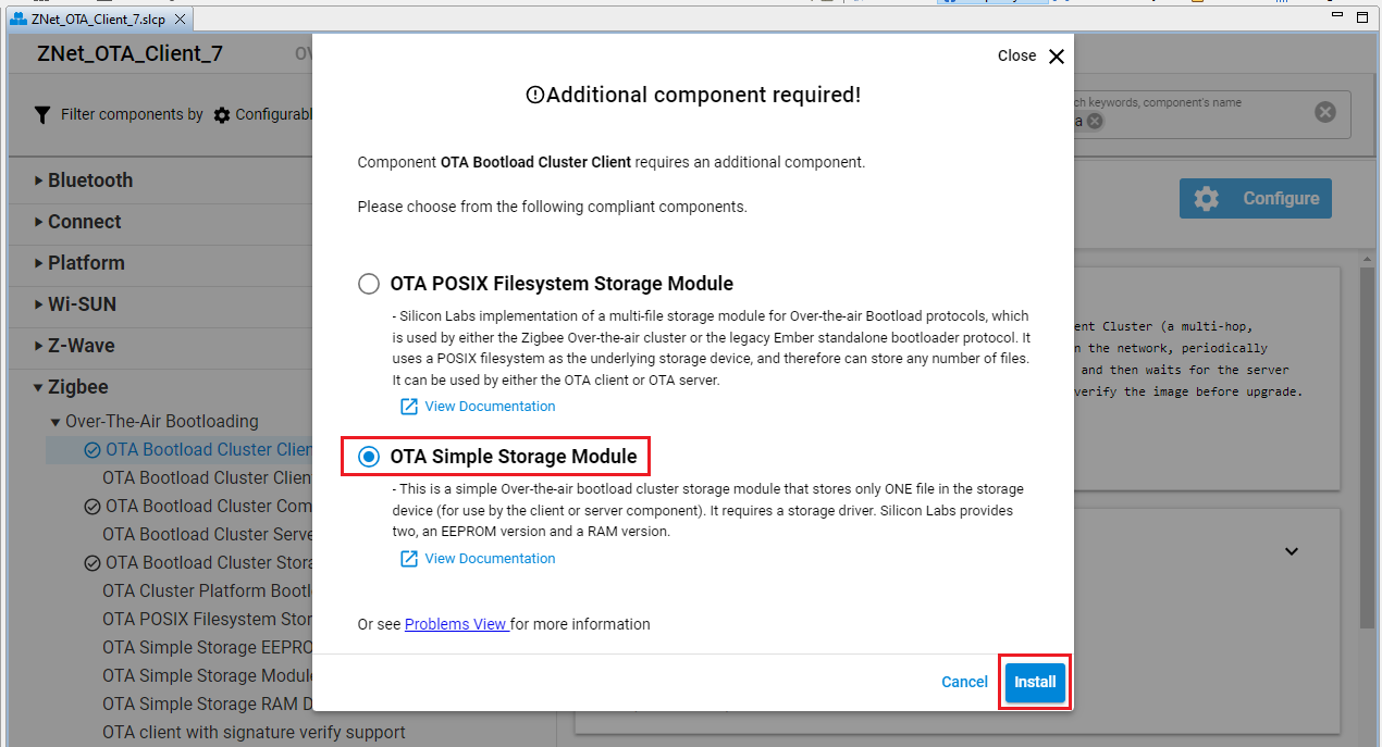
OTA Cluster Platform Bootloader
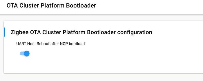
The required OTA Cluster Platform Bootloader component has only one configurable parameter as shown below:
| Parameter | Default Value | Description |
|---|---|---|
| UART Host Reboot after NCP bootload | True | This option will trigger the UART host to reboot. On Unix hosts this will trigger the process to terminate. Disabling this option will allow the UART host to continue running and just reset the NCP. SPI Hosts are always rebooted. |
OTA Simple Storage EEPROM Driver
Make sure to configure the OTA Simple Storage EEPROM Driver as in the image below. The table below the image describes each configuration parameter briefly.
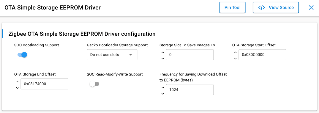
Here is a small description for each of the parameters.
| Parameter | Default Value | Description |
|---|---|---|
| SOC Bootloading Support | True | This option enables bootloading support for SOC devices. When enabled, it will re-map the OTA image file so that the GBL data is at the top of the EEPROM and therefore can be accessed by all existing Silicon Labs bootloaders. It requires that the GBL portion of the image is the first TAG in the file. The OTA storage starting offset should be 0 when this is enabled. |
| Gecko Bootloader Storage Support | Do not use Slots | This option dictates the method for saving OTA images to slots. This is only applicable if a Gecko storage bootloader is running on the chip. The Slot Manager plugin must be selected in order for slots to be used. If a Gecko storage bootloader is not present on the chip, the offsets entered below will be used. If "Do not use slots" is selected, then the offsets entered below will be used to determine where to save the image. This is not recommended, as using set offsets to addresses with a Gecko storage bootloader requires knowledge of storage slot addresses and boundaries. A mismatch in addresses will cause OTA to not work. |
| Storage Slot To Save Images To | 0 | If the user selects "Use specific slot" for Gecko Bootloader Storage Support, then this value dictates the slot to use. |
| OTA Storage Start Offset | 0 | This is the starting offset for where the OTA image will be stored in the EEPROM. |
| OTA Storage End Offset | 262144 | This is the last offset for where the OTA image may be stored in the EEPROM. |
| SOC Read-Modify-Write Support | False | This indicates to the OTA code whether the underlying EEPROM driver has support for 'read-modify-write'. Read-modify-write assumes a page erase is not required prior to writing, and any location or length of data can be re-written. If not present, then the OTA code will note each full page of data downloaded and must erase entire pages before downloading a chunk of data. |
| Frequency for Saving Download Offset to EEPROM (bytes) | 1024 | How often the current download offset is stored to EEPROM, in bytes. If set to 0 it will always be written to EEPROM. This is only used for "read-modify-write" drivers. |
OTA Bootload Cluster Storage Common Code
Configure the OTA Simple Storage EEPROM Driver as the picture below. The table below the picture describes each configuration parameter briefly.
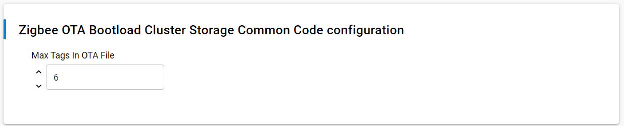
Here is a small description for each of the parameters
| Parameter | Default Value | Description |
|---|---|---|
| Max Tags In OTA File | 6 | Maximum amount of tags embedded within an OTA file. Most images will include an Upgrade Image tag, a certificate tag and a signature tag. The default max should be more than enough. |
Tags are blobs of data inside the OTA file that are interpreted by the device receiving and processing the update. A few tags are defined and global to all devices, such as the ECDSA Signature Tag and the ECDSA Signer Certificate tag. However, tags can be manufacturer-specific and contain information only pertinent to certain devices that know how to handle them. Each tag is labeled with an identification number. The list of identification numbers is specified by the OTA cluster, as shown in the following table.
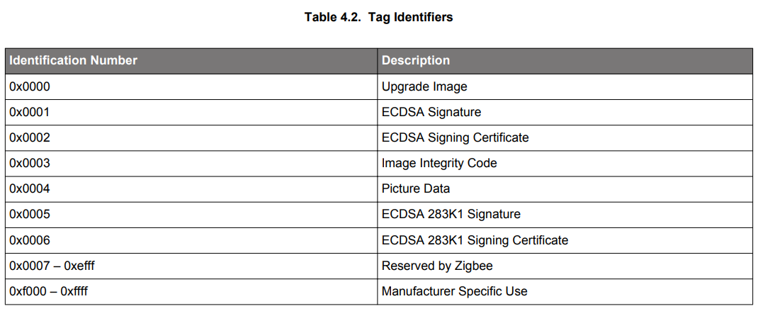
An OTA file should have at least one tag containing data that is of use to the client receiving the file. There is no limit to the maximum number of tags in the file. The main upgrade file (such as the GBL file) is normally specified as tag 0x0000 (upgrade file), but this is not required by the specification. The OTA cluster code looks for this tag when passing this data to the bootloader of the device (refer to AN716: Instructions for Using Image-Builder).
Max Tags in OTA File <1-16>
Default: 6
The following is an example of creating an OTA file and signing using a user-supplied certificate:
$ ./image-builder-ecc --create test.ota --manuf-id 0x1002 --image-type 0x5678 --version 0x00000005 --string
"EFR32 uart fifo ecc tokens" --tag-id 0x0000 --tag-file uart-fifo-ecc-tokens.gbl --sign user-supplied-cert.txt
image-builder (C) 2013 by Silicon Labs
Version: 1.5.2
ECC signature support present.
Using user supplied key and certificate.
Using Certicom TEST CA issued certificate.
Using /dev/random for random number generation
Gathing sufficient entropy... (may take up to a minute)...
File: test.ota
Magic Number: 0x0BEEF11E
Header Version: 0x0100
Header Length: 56 bytes
Field Control: 0x0000
Manufacturer ID: 0x1002
Image Type: 0x5678
Firmware Version: 0x00000005
Stack Version: 0x0002
Header String: EFR32 uart fifo ecc tokens
Total Image Size: 112044 bytes
Total Tags: 3
ID: 0x0000 (Upgrade Image)
Length: 111872 bytes
ID: 0x0002 (ECDSA Signing Certificate)
Length: 48 bytes
Subject: (>)000D6F000092E04E
Issuer: (>)5445535453454341 (Certicom TEST CA)
ID: 0x0001 (ECDSA Signature)
Length: 50 bytes
Signer: (>)000D6F000092E04E
Data: 03E9F2CE826C4CB9 B734BBA2933F1F27
3485DDE831030C78 F214589E1C46EB9D
7C50C3FFA300D4C1 8C40
Using Certicom TEST CA issued certificate.
Message Digest: 040797A3C2BC13BC04D1B5C661E4D877
Signature is valid4. Flash the Client#
Once the client image has been created, modified, and compiled, it's time to flash the image into the MG24 and verify it. Users can follow the Simplicity Studio Users Guide for more information on how to flash the image.
Note: Both the client image AND bootloader image (see: Setting up Bootloader below) will need to be flashed into the MG24 in order for the device to properly function.
Once the image is flashed, locate the WPK + MG24 combo in the "Debug Adapters" window of Simplicity Studio, right click it, and select Launch Console. In the client's CLI console, input "plugin ota-client". If set up correctly, a list of available client commands should be displayed.
Setting up Bootloader#
The bootloader on the client side will validate and copy the received OTA image to the main flash area to overwrite the current application. For these tasks, you need to configure the bootloader correctly, so it knows where the OTA image is stored and which storage mechanism is used. The configuration below is for the MG24 device; for other devices the memory layout is different and therefore the configuration can differ.
Sample Bootloader Application#
To run the OTA upgrade successfully, the bootloader must be created and configured correctly. Review UG489: Silicon Labs Gecko Bootloader User’s Guide for GSDK 4.0 and Higher or Silicon Labs Gecko Bootloader User’s Guide for Series 3 and Higher to learn more about how the bootloader works and how to configure it for OTA upgrade.
The following steps configure and build an internal storage bootloader that stores the firmware update image on an EFR32MG24 of a BRD4187C SoC board. The storage slot is configured to start at address 0x80C0000 with a size of 737 kB. This bootloader can be used by both the OTA client and server.
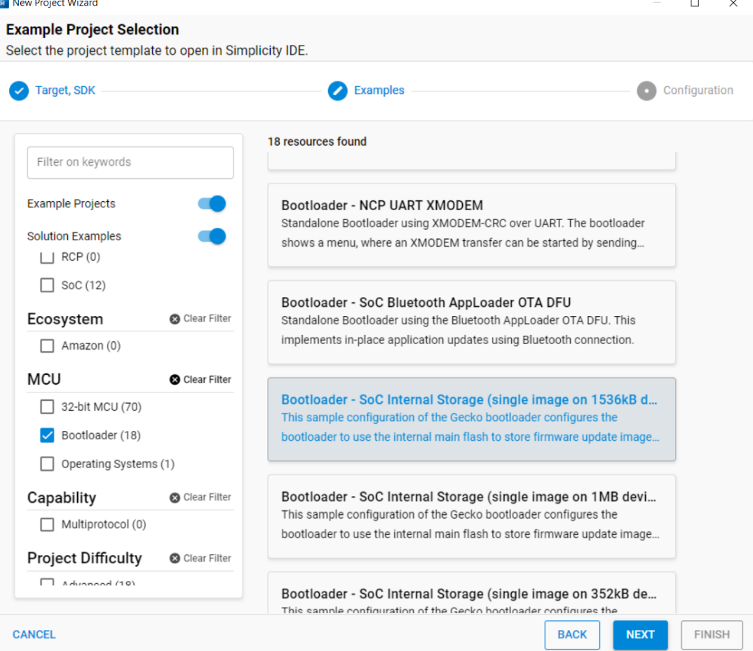
Run the New Project Wizard from Simplicity Studio (SSv5) to select and create the new internal storage bootloader project as shown below:
Once the project is created, open and configure the Bootloader Storage Slot Setup software component. Make sure the storage start address is at 0x80C0000 with a size of 0xb4000 (737kB). Ensure these values match with the OTA client’s OTA Storage Start Offset and the End Offset specified during OTA client configuration in the OTA Simple Storage EEPROM Driver component. If these values do not match, the OTA may fail.
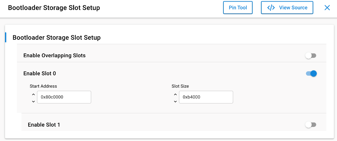
You can build and flash this example straight away if you only want to use the single image storage. When using the slot manager storage mechanism, you need to configure the start address and the size of each slot in the Bootloader Storage Slot Setup component.