Setting up a Server#
The server will operate using the Host-NCP configuration. This section outlines the setup process for a Linux-based host. It is organized into the following sub-sections:
Build the PC Host
ZAP Configuration
Install Required Components
Component Configuration
Build the NCP Server Firmware
Run the OTA Server
Some of the steps are not required for the Linux host sample application because these are already embedded into the sample application. This will be explicitly mentioned in the beginning of the paragraph.
1. Build the PC Host#
As described in the Server Requirements, a Linux system connected to a development board acting as a UART NCP or RCP is the friendliest option for an OTA server because there are many mechanisms to push OTA files into the server’s file system. In this configuration, the Linux host runs an application that communicates configurations and commands to the EFR32. In the context of OTA file transfer, this host application is in charge of locating the OTA files, initiating the server, and fragmenting an OTA image so the EFR32 can transmit it to the Zigbee network.
This section describes how to build the OTA server's host, based on the Z3Gateway sample application. It is assumed that the project will be generated in a Windows/Mac PC using Simplicity Studio and then transferred over to the Linux host (e.g. Raspberry Pi) to be compiled and executed.
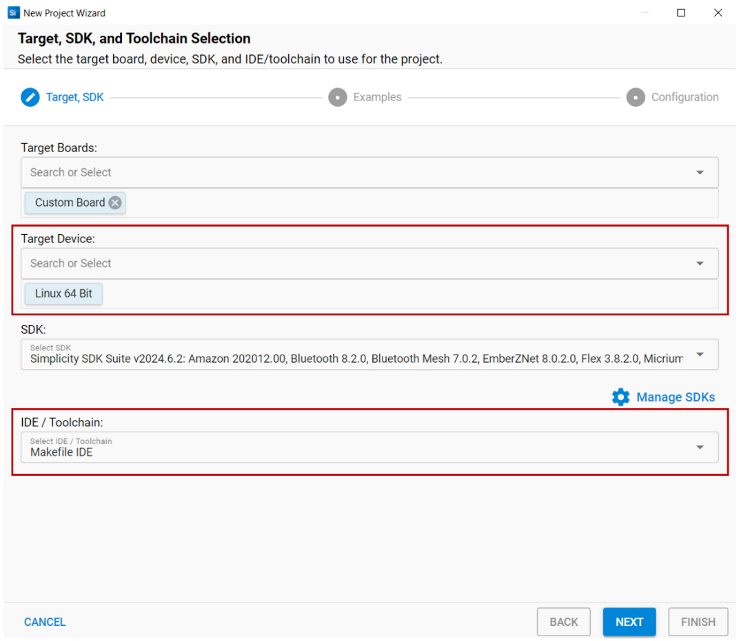
In Simplicity Studio, start the New Project Wizard. Select Linux 64 Bit as the target device and Makefile IDE as the Toolchain. Click Next.
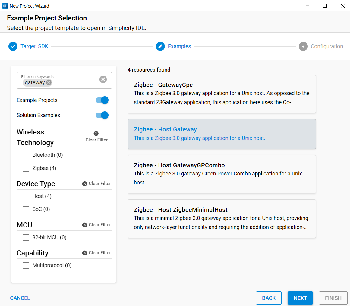
Select the Zigbee - Host Gateway application as shown below and click Next.
Select Copy contents and click Finish to create the project as shown below.
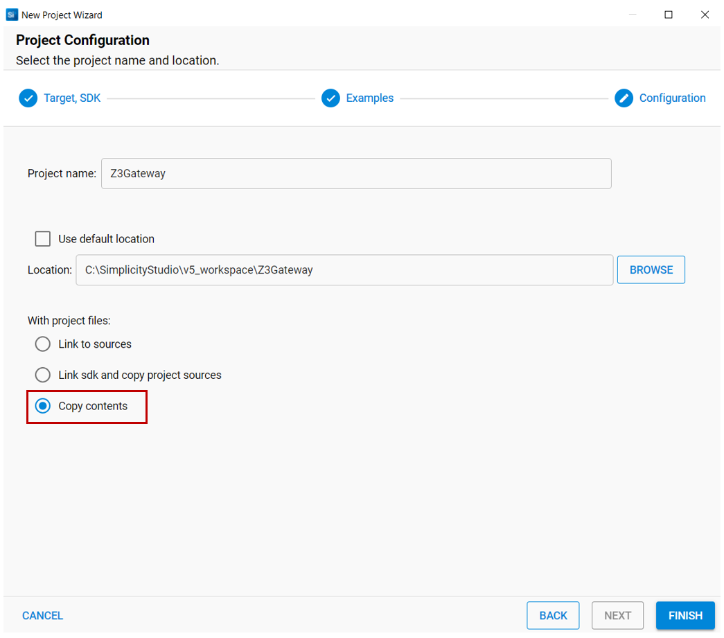
The Z3Gateway host project files are generated in the location specified in the previous step.
The steps to build the OTA server under Linux follow. The default Z3Gateway application should have all required components already installed to run the server. If users would like to configure the host application, it must be done before Step 1 below.
Copy the host's project files from the local PC to a directory on the Linux PC (e.g. user home directory). Make sure to include all files generated by Simplicity Studio.
In the Linux host, launch a Bash shell.
Change to the project directory on your Linux PC or Raspberry Pi. For example, cd /home/<UserID>/Z3Gateway
Run Make on the generated Makefile from that directory, for example make –f Z3Gateway.Makefile or simply make if the generated Makefile is in the current working directory and is specifically named Makefile.
The compilation should complete successfully with the generated Z3Gateway executable in the subdirectory ./build/debug/.
2. ZAP Configuration (Z3Gateway)#
The Zap configuration is already set up correctly on the Z3Gateway sample application, so you can skip this section.
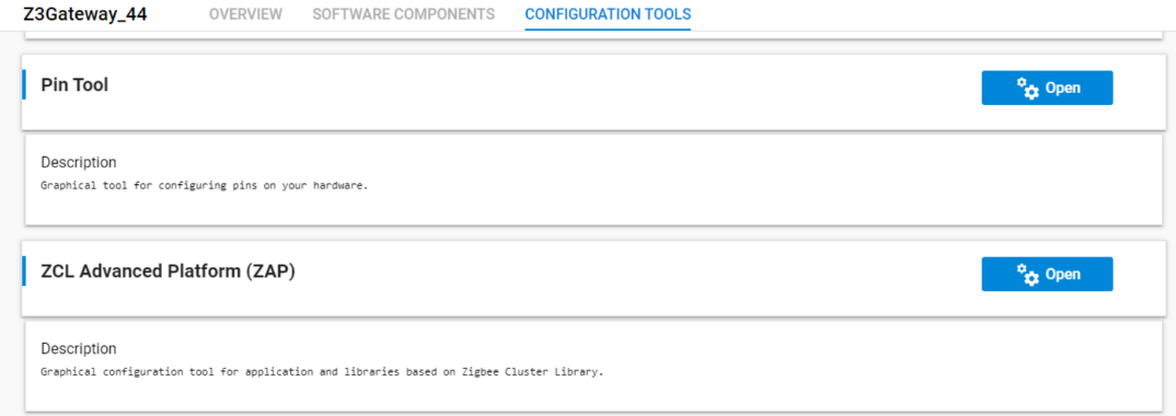
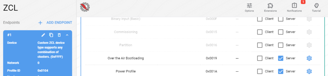
When setting up the OTA server, the first step is enabling the OTA server cluster on the device. This is done by opening the ZAP configuration tool inside your studio project. First, open the ZAP tool by opening the project (*.slcp) file, go to the Configuration Tools tab, and open the ZAP tool.
The next step is to enable the "Over the Air Bootloading" cluster as a server. First select endpoint number 1, and enable client for the cluster by checking the checkbox.
3. Install Required Components#
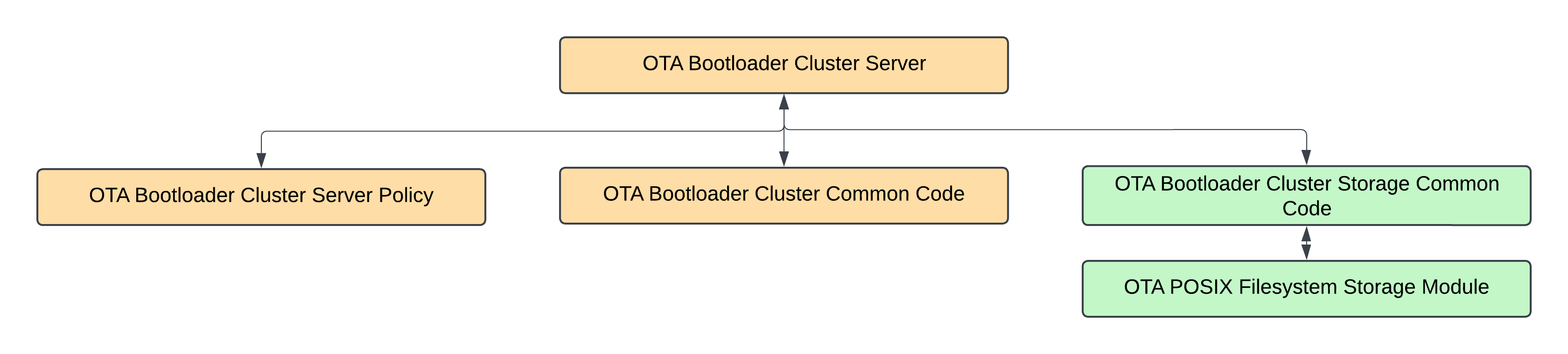
The figure below shows the dependencies between the different components. These components are already enabled in the sample application, so they don't have to be added to the project. The orange colored components handle the OTA server side, while the green colored components handle the storage of the OTA image. Because this is a Host NCP setup, the OTA images are stored on the host and use the file system for storage.
All the different components required for the OTA server are described below:
Component Name | Description |
|---|---|
OTA Bootloader Cluster Server | Silicon Labs implementation of the Zigbee Over-the-air Bootloader Server Cluster (a multi-hop, application bootloader). This implementation serves up a file from an OTA storage device and sends the data to clients. It also controls when they can upgrade to the downloaded file. |
OTA Bootloader Cluster Server Policy | Silicon Labs implementation of the server policies for the Zigbee Over-the-air bootloader cluster (a multi-hop, application bootloader). This controls when a client can upgrade, when new images are made available, and which version the client will download and install. This component should be expanded to support the developer's own server policy. |
OTA Bootloader Cluster Common Code | Common code for Silicon Labs implementation of the Zigbee Over-the-air Bootloader Cluster Client and Server components (a multi-hop, application bootloader). |
OTA Bootloader Cluster Storage Common Code | Common code for any storage module implementing an Over-the-air bootloader cluster. This is used by either the Zigbee or legacy standalone bootloader implementations. |
OTA POSIX Filesystem Storage Module | Silicon Labs implementation of a multi-file storage module for Over-the-air Bootloader protocols, which is used by either the Zigbee Over-the-air cluster or the legacy standalone bootloader protocol. It uses a POSIX filesystem as the underlying storage device, and therefore can store any number of files. It can be used by either the OTA client or OTA server. |
4. Server Component Configuration#
ZAP configuration and the OTA component are enabled by default in the Z3Gateway, allowing users to use the OTA server without making any configuration changes. You can view more details for each parameter depending on your specific use case. The following section provides more detail.
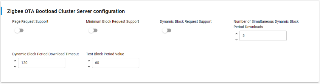
OTA Bootload Cluster Server
The configuration of the Bootload Cluster Server is the described in the picture below, each configuration parameters is described in the table below that.
| Parameter | Default Value | Description |
|---|---|---|
| Page Request Support | Disabled |
Whether the server supports clients making an OTA page request. If enabled (set to 1), the OTA server will be able to handle page requests from OTA clients. This means that when a client device requests a large block of data all at once using an OTA Page Request command,the server will be able to respond and send multiple blocks of the download image back to the client. If disabled (set to 0), the server will not support this feature, and clients will have to use individual image block requests for each block instead of page requests. |
| Minimum Block Request Support | Disabled |
Whether the server supports the Minimum Block Period support field in the Image Block Request/Response messages. This is used to rate limit clients. If enabled (set to 1), the OTA server will support the Minimum Block Period field in Image Block Request/Response messages and can specify a minimum time period that must elapse between consecutive block requests from a client. This helps in controlling the rate at which clients can request data blocks, which can be useful for managing network traffic and server load during OTA updates. The Minimum Block Period as seconds or milliseconds. When a client begins an OTA download, it is sent a Minimum Block Period with this value. The amount of time that the client delays determines whether it treats this value as seconds or milliseconds (the client's delay time is judged against a threshold of this configured value). If disabled (set to 0), the server will not support this feature, and clients will not be rate-limited based on a minimum block period. |
| Dynamic Block request Support | Disabled |
If the Minimum Block Request Support is enabled, this additional support provides dynamically treating the Minimum Block Period field as milliseconds or seconds, depending on the OTA client's support. When a client starts an OTA transfer, it will be tested to determine whether it treats the Minimum Block Period as seconds or milliseconds, and the determination will be used throughout the OTA transfer. When enabled, the OTA server will dynamically determine whether to treat the Minimum Block Period field as milliseconds or seconds, based on the client's behavior.The server tests each client at the start of an OTA transfer to determine how it interprets the Minimum Block Period field. This is done by sending a preset delay value to the client and observing its response time. Once the server determines whether the client treats the period as milliseconds or seconds, it uses this information consistently throughout the rest of the OTA transfer for that particular client. If disabled, the OTA server will not use the dynamic treatment of the Minimum Block Period field. |
| Number of Simultaneous Dynamic Block Period Downloads | 5 |
If the Dynamic Minimum Block Request Support is enabled, this option's value dictates how many simultaneous OTA client transfers are supported at one time. When at full capacity, Query Next Image Requests will be responded to, but Image Block Requests and Page Requests will be told to delay until a free connection opens up, which will occur when a device concludes the OTA process. A device will be aged out as an active connection if it does not query a piece of the OTA file at least once every 'Dynamic Block Period Download Timeout' seconds. This parameter is only relevant when the Dynamic Minimum Block Request Support is enabled (EMBER_AF_PLUGIN_OTA_SERVER_DYNAMIC_MIN_BLOCK_PERIOD_SUPPORT is set to 1). It limits the number of concurrent OTA downloads that the server can manage using the dynamic block period feature. This helps in controlling server resources and network traffic. |
| Dynamic Block Period Downloads Timeout | 120 |
This option's value dictates the amount of inactivity in seconds before the server purges a client from the dynamic block period downloads. This value must be greater than the 'Test Block Period Value' below, otherwise a client who resumes querying after a test delay will be immediately purged. This parameter is used when the Dynamic Minimum Block Request Support is enabled (EMBER_AF_PLUGIN_OTA_SERVER_DYNAMIC_MIN_BLOCK_PERIOD_SUPPORT is set to 1). If a client doesn't request any part of the OTA file for the duration specified by this parameter, it will be purged or removed from the server's list of active dynamic block period downloads. This timeout helps manage server resources by freeing up slots for new clients when existing clients become inactive. |
| Test Block Period Value | 60 |
The value a client is told to delay when determining whether it treats the Minimum Block Period as seconds or milliseconds. When a client begins an OTA download, it is sent a Minimum Block Period with this value. The amount of time that the client delays determines whether it treats this value as seconds or milliseconds (the client's delay time is judged against a threshold of this configured value). It is recommended that this value not be less than the longest expected delay time in the network, as sleepy end devices may delay longer than the Minimum Block Period amount, which tricks the OTA server into thinking that the client treats this value as seconds. Once the client is judged to be using seconds or milliseconds, the Minimum Block Period will revert to being the value contained in the otaMinimumBlockPeriodMs variable, which is settable with "plugin ota-server policy image-req-min-period". This parameter is used when the Dynamic Minimum Block Request Support is enabled (EMBER_AF_PLUGIN_OTA_SERVER_DYNAMIC_MIN_BLOCK_PERIOD_SUPPORT is set to 1). When a client begins an OTA download, the server sends this value as the initial Minimum Block Period. The server then observes how long the client actually delays before its next request:
After this determination, the server switches to using the actual Minimum Block Period value (set by otaMinimumBlockPeriodMs) for the rest of the download process. |
OTA Bootload Cluster Storage Common Code
See component OTA Bootload Cluster Storage Common Code in the Client Component Configuration.
5. Build the NCP Server Firmware#
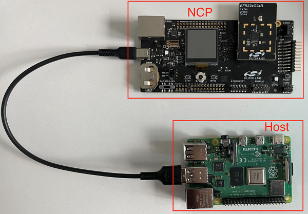
The NCP device used in this guide is based on the EFR32MG24 (BRD4187C) and is connected to the host system via UART through a development kit. Communication between the host application—Z3Gateway, in this case—and the NCP is handled using the EmberZNet Serial Protocol (EZSP) over the UART interface provided via USB.
To enable this setup, the EZSP NCP firmware must be built and flashed onto the EFR32MG24 target device. For this purpose, we can use Silicon Labs’ “ncp-uart-hw” sample application, which is specifically designed for UART-based NCP communication.
Navigate to File > New > Silicon Labs Project Wizard. From there, select the appropriate device, board, compiler, and stack. Once you've located the sample application (as shown in the image below), select it and click Finish to complete the setup.
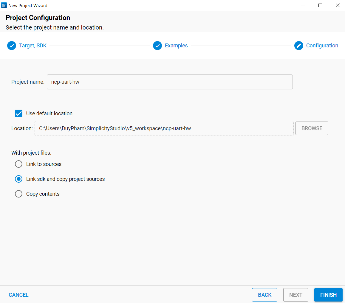
The default "ncp-uart-hw" sample application comes with all the required components to run the OTA server, so no configuration is required. Once the sample application is created, build the project and flash both the appropriate bootloader and NCP firmware into the device.
If you are using the same board (for example, BRD4187C for both the SoC server and the client's NCP), you can use the same bootloader for both boards. Users can follow the Simplicity Studio User's Guide for more information on how to flash the image.
Now that the host and NCP software have been created, you can run the OTA server.
6. Run the OTA Server#
Make sure the WPK for the NCP device is connected to the Host/PC with a USB cable as shown below:
NCP Checklist:
Bootloader (bootloader-storage-internal-single-1536k.s37 for MG24) has been flashed.
NCP image has been flashed.
Host Checklist:
Z3Gateway executable can be found on the host.
Launch the OTA Server by executing the OTA server application from the command line while passing in the location of the communication port. The communications port will be either a USB or serial port device. The method for determining which port the EFR32MG24 is connected to depends on the operating system of the host PC. Under Linux, the USB port is usually registered as /dev/ttyUSBX, where X is a number as assigned by the operating system. For example, the following would use ttyUSB0.
Launch a Linux Shell.
Change to the directory where the OTA Server application image is located. For example: cd /home/<UserID>/Z3Gateway/build/debug/.
Start the server by running ./Z3Gateway –p /dev/ttyUSB0.
If run correctly, users should see the following output:
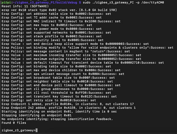
You can enter plugin ota-server to view a list of available server commands.