Performing RF Calibration#
The crystal calibration for SiWx917 NCP IC can either be done in Burst Mode or Continuous Wave (CW) mode. For more details, refer to SiWx917 QMS Crystal Calibration App Note.
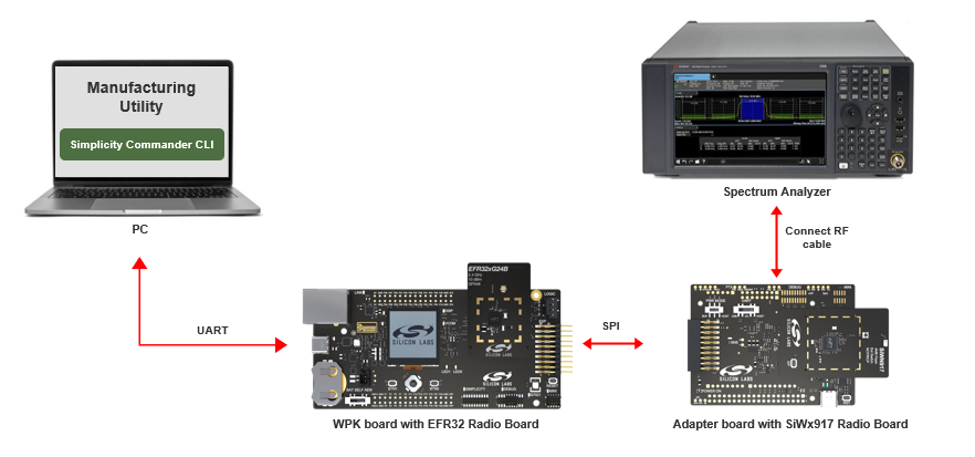
Setup#
Ensure the SiWx917’s RF port is connected to Spectrum Analyzer as shown below:
Transmission in Burst Mode#
This mode requires a test instrument that supports modulation analysis where frequency error can be reported by the instrument directly.
Steps for Frequency Offset Correction#
Set up the radio and start transmission.
commander manufacturing radio --power 16 --phy 6MBPS --channel 1 --start -d <full opn> --serialinterfaceCheck the frequency error on the instrument. Adjust the XO CTUNE values by providing the frequency error as input. Provide this frequency error as frequency offset. This value can be ranging from –255 to 255.
commander manufacturing xocal --offset <Offset> -d <full opn> --serialinterface --skipinit --skiploadObserve the updated frequency error on the instrument. If the frequency error is not within +/-2 KHz, a new round of frequency error can be processed via step 2. This process may be repeated until the frequency error is brought within the tolerance limit (+/-2 KHz).
Store the XO CTUNE value in eFuse (OTP) or Flash. The radio transmission will stop.
eFuse:
commander manufacturing xocal --storeinefuse -d <full opn> --serialinterface --skipinit -skiploadFlash:
commander manufacturing xocal --store -d <full opn> --serialinterface --skipinit --skipload
Steps for Gain Offset Calibration#
Set up the radio and start RF transmission in Burst mode.
commander manufacturing radio --power 16 --phy 6MBPS --channel 1 --start -d <full opn> --serialinterfaceMeasure the output power with the instrument that has the capability of measuring burst power. For example, Keysight instrument with modulation analysis measurement setting capability shows the burst packet power.
Calculate the offset to meet the expected output power (16 dBm).
Offset = ceil ((output power measure (dBm) + cable loss -- 16) * 2)
Store the gain values for channel 1.
commander manufacturing gain --ch1 <Offset> --skipload -d SiWG917M111MGTBA --serialinterface --skipinitRepeat from step 1 for channel 6 and 11. In step 4, replace
--ch1with--ch6and--ch11when measuring for channel 6 and 11 respectively.Stop the radio.
commander manufacturing radio --stop --skipload -d SiWG917M111MGTBA --serialinterface --skipinit
Transmission in Continuous Mode#
Steps for Frequency Offset Correction#
Set up the radio and start transmission.
commander manufacturing radio --power 16 --phy CW --channel 1 --start --noburst -d <full opn> --serialinterfaceMeasure the frequency on the instrument using peak search (use the instrument which supports spectrum mode/modulation).
Adjust the CTUNE values by providing the frequency error as input. This is a frequency offset correction, with the value ranging from –255 to 255.
Offset = measured frequency (in kHz) -- 2412000
commander manufacturing xocal --offset <Offset> --skipload -d SiWG917M111MGTBA --serialinterface --skipinitCheck the instrument and verify that the channel frequency is within expectations. If not, repeat from step.
Store the CTUNE values. The radio transmission will stop.
commander manufacturing xocal --store --skipload -d SiWG917M111MGTBA --serialinterface --skipinit
Steps for Gain Offset Calibration#
Setup the radio and start transmission on channel 1.
commander manufacturing radio --power 16 --phy 6MBPS --channel 1 --noburst --start -d SiWG917M111MGTBA --serialinterfaceMeasure the output power (use the instrument which supports spectrum mode/modulation). Measure the integrated power in 20 MHz bandwidth.
Calculate the offset to meet the expected output power (16 dBm).
Offset = ceil ((output power measure (dBm) + cable loss -- 16) * 2)
Store the gain values for channel 1.
commander manufacturing gain --ch1 <Offset> --skipload -d SiWG917M111MGTBA --serialinterface --skipinitRepeat from step 1 for channel 6 and 11. In step 4 the replace
–ch1with--ch6and--ch11when measuring for channel 6 and 11 respectively.Stop the radio.
commander manufacturing radio --stop --skipload -d SiWG917M111MGTBA --serialinterface --skipinit