Security Features#
Secure Boot#
To protect your software intellectual property (IP) and maintain your competitive edge in the market, you can configure or enable/disable a pre-flashed secure bootloader on the devices. Secure Boot ensures that only authenticated code can run on the device. If a device fails its security check, it is not allowed to run, and program control will typically stall in the validating module.
The Security Bootloader, which runs on the Network Wireless Processor (NWP), implements Secure Boot. Here is an overview of the Secure Boot process:
Upon reset, the Security Bootloader configures the module hardware based on the configurations present in the flash or eFuse.
The Security Bootloader authenticates the device configurations in the flash or efuse (OTP) using keys in OTP.
The Security Bootloader validates the integrity and authenticity of the NWP connectivity firmware in the flash and then invokes/loads the firmware.
To enable only Secure Boot or Secure Boot along with other security features, refer to the Security Levels section.
Secure Firmware Update#
The secure firmware update feature of the bootloader ensures the authenticity and integrity of the connectivity firmware image. The bootloader updates the image only after successfully validating its authenticity and integrity. It also prevents downgrades to a lower version of firmware using the anti-rollback feature (ta_anti_roll_back) if enabled.
Additionally, the bootloader supports transparent migration to a wirelessly updated image and provides recovery mechanisms to protect against failures. The NWP Bootloader uses a proprietary format for its connectivity firmware images, known as RPS, with files having the extension .rps.
The connectivity firmware image supports the following security levels:
No Security: CRC is calculated and verified against the default CRC of the image within the RPS header.
Secure Boot: The Message Integrity Check (MIC) of the firmware is verified on every boot to check its integrity.
Message Integrity Check (MIC) + Signature: The MIC is calculated for the firmware image and saved within the RPS header. The size of the image in the RPS header is incremented by the size of the signature. Finally, the signature of the entire RPS file (RPS Header + image) is calculated and appended to the end of the file.
MIC + Encryption + Signature: The MIC is calculated for the firmware image and saved within the RPS header. The image is then encrypted and appended to the RPS header. The image can be encrypted using AES CTR or XTS mode. The size of the image in the RPS header is incremented by the size of the signature. Finally, the signature of the entire RPS file (RPS Header + image) is calculated and appended to the end of the file.
These security features are classified into different security levels. For guidance on selecting the appropriate security level, please refer to the Security Levels section.
Note: Once you are done backing up the files and Security Key Programming is done, then you only need to add security to the SiWx917 connectivity firmware image and flash the secure image.
Security Key Programming#
To enable security features (encryption/MIC/signature) on your SiWx917 device, the device's Physically Unclonable Function (PUF) first needs to be initialized and an activation code must be generated on the device. This part of manufacturing includes generation of static keys and PUF generated keys and loading them into flash. While programming the static keys, the keys are saved in wrapped format in the flash. There are multiple keys that are generated inside and outside of device. Refer to Secure Key Management and Protection section for information on keys generated at commander and PUF Intrinsic keys.
The Security Key Programming sequence is as follows:
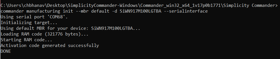
Step 1: Generate Activation Code and Flash#
The activation code is generated by the Physical Unclonable Function (PUF) module embedded within the device. Once this code is generated, the firmware will securely write the activation code into the device's Flash memory.
Command syntax:
commander manufacturing init [--mbr <filename.bin|’default’> -d <full OPN>] --serialinterface
Example:
commander manufacturing init --mbr default -d SiWN917M100LGTBA –serialinterface
Return Codes:
Success: Activation Code gets generated
Failure: Refer to Possible Error Codes and try again
Step 2: Power Cycle the Device#
Users must power cycle the device after the Activation Code Generation and Flashing process. This mandatory step is required by the Hardware PUF block to set the security module into a ready state.
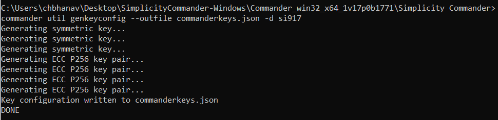
Step 3: Generate Security Keys from Commander#
Generate the key configuration and save it as a JSON file for a SiWx917 device. This key configuration includes the OTA key, OTP AES key, OTP public key, OTP private key, TA (NWP) public key, and TA (NWP) private keys.
Command syntax:
commander util genkeyconfig --outfile <keys.json> -d <'si917' | <fullopn>
Example:
commander util genkeyconfig --outfile commanderkeys.json -d si917
Alternatively, users can generate keys themselves using their preferred tools and save them as a JSON file.
Return Codes:
Success: Key configuration is saved as a JSON file.
Failure: Refer to Possible Error Codes and try again.
Step 4: Load the Security Keys and Program the NWP MBR with Security#
Load the Security Keys, configure the security level, PUF activation code address and key descriptor table, and program the NWP MBR. It is important to understand the security levels before proceeding with this step.
Security Levels#
SiWx917 NCP offers various security features like Message Integrity Check (MIC), Signature, Encryption, etc., for NWP. There are three levels of security.
Security Level 1 (Low security level)
If the user wants to enable only secure boot, this level should be selected. This Security Level ensures that the bootloader performs MIC of the RPS during both firmware loading and firmware update.
For Security Level 1, do the following configurations in the MBR fields:
MBR:
{ "efuse_data": { "ta_secure_boot_enable": 1 } }eFuse (OTP):
{ "bootloader_config": { "ta_secure_boot_enable": 1 } }Security Level 2 (Partial security level)
If the user wants to enable Secure boot along with Signature validation of the RPS (firmware) image, this level should be selected. This Security Level ensures the bootloader performs MIC and Signature validation of the RPS during both firmware loading and firmware update.
For Security Level 2, do the following configurations in the MBR fields:
MBR:
{ "efuse_data": { "ta_secure_boot_enable": 1, "ta_digital_signature_validation": 1 } }eFuse (OTP):
{ "bootloader_config": { "ta_secure_boot_enable": 1, "ta_digital_signature_validation": 1 } }Security Level 3 (Full security level)
If the user wants to enable Secure Boot, Signature Validation, and Encryption, this level should be selected. This Security Level ensures the MIC, Signature validation, and Encryption of the RPS during Firmware loading and Firmware update and Inline Encryption while saving the firmware in the flash.
For Security Level 3, do the following configurations in the MBR fields:
MBR:
{ "efuse_data": { "ta_secure_boot_enable": 1, "ta_digital_signature_validation": 1, "ta_encrypt_firmware": 1 } }eFuse (OTP):
{ "bootloader_config": { "ta_secure_boot_enable": 1, "ta_digital_signature_validation": 1 }, "ta_config": { "ta_encrypt_firmware": 1 } }
With a clear understanding of the programmable security fields and security levels in MBR and eFuse, define the PUF activation code Address, Security level, and Key descriptor table address in a .json file. Below is the sample JSON file enablesecurity.json. Provision the keys contained in the JSON file (in step 3) to the SiWx917 device with the –keys option.
{
"puf_activation_code_addr": 8192,
"efuse_data": {
"ta_secure_boot_enable": 1,
"ta_digital_signature_validation": 1,
"ta_encrypt_firmware": 1
},
"key_desc_table_addr": 768
}MBR:
Command syntax:
commander manufacturing provision --mbr <ta_mbr_SiWN917M100LGTBA.bin | 'default'> --keys <keys.json> --data <securitylevelsfilename.json> -d <full opn> --serialinterfaceExample:
commander manufacturing provision --mbr default --keys commanderkeys.json --data enablesecurity.json -d SiWN917M100LGTBA --serialinterface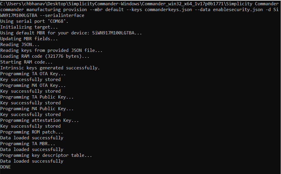
After the above command is processed, it implies that selected level of security is enabled for SiWx917 device.
Add Security to NWP Connectivity Firmware#
When the Security is enabled in the device, you must load the secured NWP connectivity firmware. If you try to Flash the non-secured image, the system will throw an error, and the firmware image loading fails.
Secure NWP Connectivity Firmware#
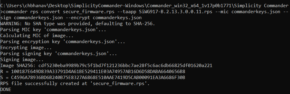
Give the following command to convert the already existing non-secure (no encryption, MIC, or signature) RPS NWP connectivity images into secure images by applying AES-ECB encryption, AES-CBC MIC integrity check, and ECDSA signatures.
Command Syntax:
For Security level 1:
commander rps convert <output_filename.rps> --taapp <original_unsecured_firmware.rps> --mic <commanderkeys.json>For Security level 2:
commander rps convert <output_filename.rps> --taapp <original_unsecured_firmware.rps> --mic <commanderkeys.json> --sign <commanderkeys.json>For Security level 3:
commander rps convert <output_filename.rps> --taapp <original_unsecured_firmware.rps> --mic <commanderkeys.json> --sign <commanderkeys.json> --encrypt <commanderkeys.json>
The above command creates a secure NWP connectivity firmware image.
Debug Lock#
Configure the debug port securely before the ICs/modules leave the factory with the Debug Lock Feature (which can be unlocked with a token).
The SiWx917 NCP has a hardware debug solution. This provides high system visibility of the processor and memory through either a traditional JTAG port or a 2-pin Serial Wire Debug (SWD) port that is ideal for small package devices. The Secure Lock Feature locks the Debug Port. Any unauthorized access will be restricted.
This will be a one-time update of the MBR. This update should happen when the user has completed the development phase and entered the manufacturing phase for their products. Refer to the AN1428: SiWx917 Debug Lock for more information on enabling debug lock.