Introduction#
This document describes the manufacturing procedure to be followed when procuring the SiWG917 (SiWx917 SoC) IC/Module, based on the Ordering Part Number (OPN), flash mode, and security specifications.
The SiWG917 comprises two processors: Silicon Labs' Network Wireless Processor (NWP) and an ARM® Cortex® M4 Processor. The NWP subsystem is responsible for executing all networking and wireless stacks on independent threads and functions as the secure processing domain, overseeing secure boot, secure firmware updates, and debug lock. The Cortex-M4 processor is dedicated to peripheral and application-related processing.
Manufacturing Procedure#
Based on the OPN, the SiWG917 can be equipped with either 4 or 8 MB of "In-package" Quad SPI (QSPI) flash. Additionally, the SiWG917 supports external flash options of up to 16 MB. The QSPI serves as the interface for accessing the flash memory.
Note: External 16 MB Flash is not supported by latest available SiWG917 MBR. For information regarding software roadmap features, lists of available features, and profiles, contact Silicon Labs or refer to document related to SiWG917 MBR (Release Notes and Reference Manuals).
The SiWG917 operates in common flash mode, where a single flash memory is shared between the NWP and M4 processors.
For OPNs without in-package flash, enable common flash mode. Refer to the Flash Mode Selection – No In-Package Flash OPN for the steps to select the common flash mode.
For OPNs with 4 MB or 8 MB in-package flash, the device is configured to operate in common flash mode by default.
The following flow chart illustrates the SiWG917 manufacturing procedure.
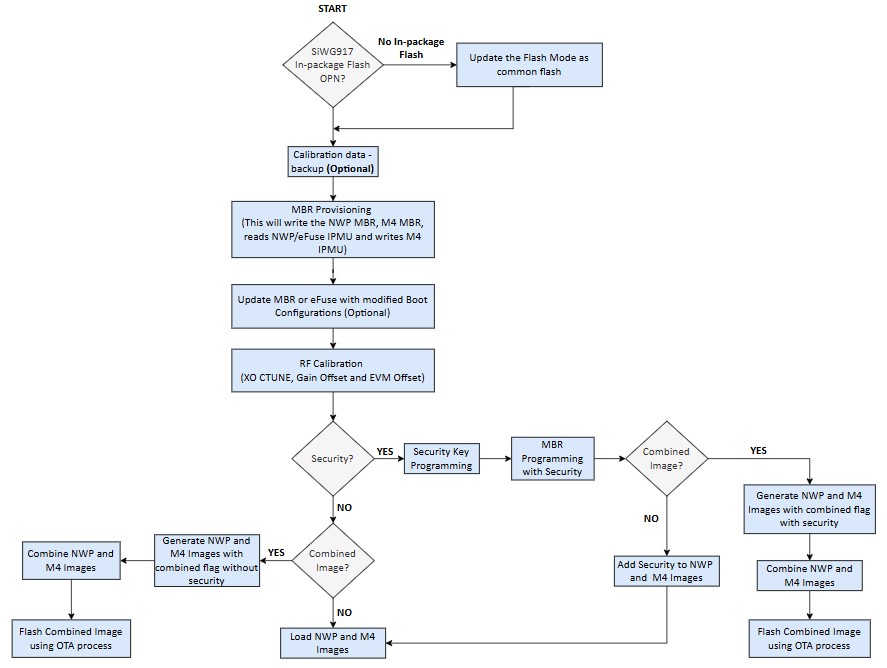
Verify the Flash Mode
Check whether the SiWG917 is in common Flash mode.
Master Boot Record (MBR) Configuration Based on OPN
MBR is stored in flash and contains information such as clock frequencies, offsets of structures like device specific configurations, SPI configurations, external flash details, and so on.
Enable security
The security fields in the MBR, PUF activation code, key descriptors, and the keys must be programmed in the device while enabling the security features.
RF Calibration (Frequency and Gain Offset)
The Crystal Oscillator Capacitor tune (XO CTUNE) is used to adjust frequency, gain offset adjustments can be done in burst, continuous and continuous wave mode in the SiWG917 using the manufacturing utility.
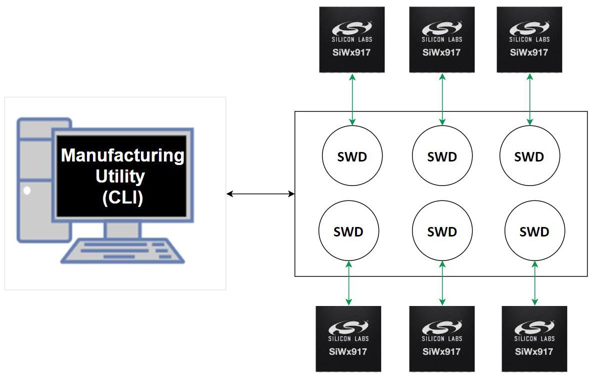
Manufacturing Utility#
The Manufacturing Utility operates in conjunction with Simplicity Commander via Command Line Interface (CLI). The CLI facilitates interaction with the commander to execute the manufacturing procedure. Multiple instances of the commander can support multiple devices, enabling simultaneous programming of production information into the SiWG917.
Simplicity Commander CLI#
There are two methods to access the Simplicity Commander CLI.
Simplicity Commander (as part of tools in Simplicity Studio)
Simplicity Commander (individually installed)
Note: When configuring the SiWG917, you must use the latest version of Simplicity Commander. In contrast not doing so might result the device to act in an unexpected manner.
Enter “cmd” in the Simplicity Commander Installed path to open the commander CLI.
Example: For Simplicity Commander (As part of tools in Simplicity Studio), go to the path:
$:\...\SimplicityStudio\v5\developer\adapter_packs\commander and enter "cmd" in the address bar and press Enter.

Manufacturing Utility Commands – Parameters#
The following table lists the various parameters that are used by the commands mentioned in the subsequent sections.
| Field | Description | ||||||||
|---|---|---|---|---|---|---|---|---|---|
provision |
Writes NWP MBR, M4 MBR, Reads, and Writes M4 IPMU in Common flash mode | ||||||||
write |
Compares the provided MBR file in the command and the MBR file already present inside the device and writes the new changes into the MBR | ||||||||
read |
Read the contents | ||||||||
init |
Generate the activation code | ||||||||
--mbr |
Master Boot Record | ||||||||
--keys |
Security keys | ||||||||
m4mbrcf |
Common flash M4 MBR | ||||||||
m4ipmucf |
M4 IPMU data for common flash configuration | ||||||||
efusecopy |
Updating eFuse data to flash for selected region | ||||||||
<full opn> |
Provide the OPN number. Example: SiWG917M111MGTBA | ||||||||
<updated-mbr-fields.json> |
File in which security level is programmed | ||||||||
-d |
Device | ||||||||
--skipload |
Skip loading manufacturing firmware (loaded by the commander CLI in the device RAM, when the first command is given from the CLI) when the command is given. Note: Make sure the first command given to the device using commander CLI does not have the -- skipload each time the device is powered ON. |
||||||||
--pinset [n]
|
Should be given for no in-package flash
|
||||||||
--start |
Turn on the radio transmission | ||||||||
--stop |
Turn off the radio transmission | ||||||||
--noburst |
Transmission happens continuously instead of being in bursts | ||||||||
--internalant |
Select virtual internal RF switch. By default, the external antenna RF switch configuration is selected. | ||||||||
--ctuneoverride |
It writes the XO CTUNE value into the flash instead of adding the frequency offset to already present value. | ||||||||
--store |
Computed values are stored in flash | ||||||||
--storeinefuse |
Compute values are stored in eFuse |
Supported OPNs#
| Product Type | OPN | OPN to be used in commands | Description |
|---|---|---|---|
| IC | SiWG917M111XGTBA | SiWG917M111XGTBA | No in-package flash |
| IC | SiWG917M110LGTBA | SiWG917M110LGTBA | 4 MB in-package flash |
| IC | SiWG917M100MGTBA | SiWG917M100MGTBA | 8 MB in-package flash |
| IC | SiWG917M111MGTBA | SiWG917M111MGTBA | 8 MB in-package flash |
| IC | SiWG917M121XGTBA | SiWG917M121XGTBA | No in-package flash, 2 MB stacked PSRAM |
| IC | SiWG917M141XGTBA | SiWG917M141XGTBA | No in-package flash, 8 MB stacked PSRAM |
| Module | SiWG917Y110LGNBA / SiWG917Y110LGNXA | SiWG917M110LGTBA | 4 MB Flash, No Antenna |
| Module | SiWG917Y111MGNBA / SiWG917Y111MGNXA | SiWG917M111XGTBA | 8 MB Flash, No Antenna, MVP |
| Module | SiWG917Y121MGNBA / SiWG917Y121MGNXA | SiWG917M121XGTBA | 8 MB In-Module Flash, 2 MB stacked PSRAM, No Antenna, MVP |
| Module | SiWG917Y110LGABA / SiWG917Y110LGAXA | SiWG917M110LGTBA | 4 MB Flash, Integrated Antenna |
| Module | SiWG917Y111MGABA / SiWG917Y111MGAXA | SiWG917M111XGTBA | 8 MB Flash, Integrated Antenna, MVP |
| Module | SiWG917Y121MGABA / SiWG917Y121MGAXA | SiWG917M121XGTBA | 8 MB In-Module Flash, 2 MB stacked PSRAM, Integrated Antenna, MVP |