BT Powersave#
1. Purpose / Scope#
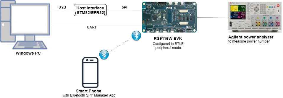
This application demonstrates the process of configuring the device in power save in BT connected mode in bt_power_save example.
2. Prerequisites / Setup Requirements#
Before running the application, the user will need the following things to setup.
2.1 Hardware Requirements#
Windows PC with Host interface(UART/ SPI).
Silicon Labs RS9116 Wi-Fi Evaluation Kit
Host MCU Eval Kit. This example has been tested with:
Silicon Labs WSTK + EFR32MG21
Smartphone with spp manager app
Agilent power analyzer
2.2 Software Requirements#
Embedded Development Environment
For STM32, use licensed Keil IDE
For Silicon Labs EFx32, use the latest version of Simplicity Studio
Download and install the Silicon Labs Bluetooth SPP manager in the android smart phones for testing BT applications. Users can also use their choice of BT apps available in Android/iOS smart phones.
3. Application Build Environment#
3.1 Platform#
The Application can be built and executed on below Host platforms
3.2 Host Interface#
By default, the application is configured to use the SPI bus for interfacing between Host platforms and the RS9116W EVK.
The SAPI driver provides APIs to enable other host interfaces if SPI is not suitable for your needs.
3.3 Project Configuration#
The Application is provided with the project folder containing Keil and Simplicity Studio project files.
Keil Project
The Keil project is used to evaluate the application on STM32.
Project path:
<SDK>/examples/snippets/bt/bt_power_save/projects/bt_power_save-nucleo-f411re.uvprojx
Simplicity Studio
The Simplicity Studio project is used to evaluate the application on EFR32MG21.
Project path:
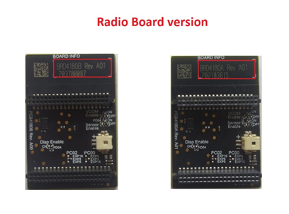
If the Radio Board is BRD4180A or BRD4181A, then access the path
<SDK>/examples/snippets/bt/bt_power_save/projects/bt_power_save-brd4180a-mg21.slsprojIf the Radio Board is BRD4180B or BRD4181B, then access the path
<SDK>/examples/snippets/bt/bt_power_save/projects/bt_power_save-brd4180b-mg21.slsprojUser can find the Radio Board version as given below
3.4 Bare Metal Support#
This application supports only bare metal environment. By default, the application project files (Keil and Simplicity Studio) are provided with bare metal configuration.
4. Application Configuration Parameters#
The application can be configured to suit your requirements and development environment. Read through the following sections and make any changes needed.
4.1 rsi_bt_power_save_profile.c file and update/modify following macros.
RSI_BT_LOCAL_NAME - Name of the Wyzbee (Master) device
PIN_CODE - Four-byte string required for pairing process.
PSP_TYPE – Power save profile type.
Note: 1. PSP_TYPE is only valid RSI_SLEEP_MODE_2. 2. RSI_MAXRSI_MAX_PSP is only valid in case of BT._PSP is only valid in case of BT.
SNIFF_MAX_INTERVAL - Sniff Maximum interval value
SNIFF_MIN_INTERVAL – Sniff Minimum interval value
SNIFF_ATTEMPT - Sniff Attempt Value
SNIFF_TIME_OUT – Sniff Timeout Value
To Enable Power Save
PSP_MODE refers power save profile mode. The WiSeConnect device supports following power modes in BT
RSI_ACTIVE (0): In this mode, the module is active and power save is disabled.
RSI_SLEEP_MODE_2 (1): This mode is applicable when the module is connected state. In this sleep mode, SoC will go to sleep based on GPIO handshake or Message exchange, therefore handshake is required before sending data to the module.
RSI_SLEEP_MODE_8 (8): In this power mode, the module goes to power save when it is in the unassociated state with the remote device. In this sleep mode, SoC will go to sleep based on GPIO handshake or Message exchange, therefore handshake is required before sending the command to the module.
#define PSP_MODE RSI_SLEEP_MODE_2Note: For RSI***SLEEP_MODE_2* and *RSI_SLEEP_MODE_8* *modes**,* GPIO or Message based handshake can be selected using *RSI_HAND_SHAKE_TYPE* macro which is defined in *rsi_wlan_config.h***
Note: In this example, user can verify RSI_SLEEP_MODE_2 with Message based handshake. If the user wants to verify other power modes, the user has to change the application as well as GPIO handshake signals
PSP_TYPE refers power save profile type. The WiSeConnect device supports following power save profile types in BT mode,
RSI_MAX_PSP (0): In this mode, the WiSeConnect device will be in Maximum power save mode. i.e. Device wakes up for every DTIM beacon and does data Tx and Rx.
#define PSP_TYPE RSI_MAX_PSP4.2 Open rsi_wlan_config.h file and update/modify following macros,
#define CONCURRENT_MODE RSI_DISABLE
#define RSI_FEATURE_BIT_MAP FEAT_SECURITY_OPEN
#define RSI_TCP_IP_BYPASS RSI_DISABLE
#define RSI_TCP_IP_FEATURE_BIT_MAP TCP_IP_FEAT_DHCPV4_CLIENT
#define RSI_CUSTOM_FEATURE_BIT_MAP FEAT_CUSTOM_FEAT_EXTENTION_VALID
#define RSI_EXT_CUSTOM_FEATURE_BIT_MAP (EXT_FEAT_LOW_POWER_MODE\|EXT_FEAT_XTAL_CLK_ENABLE\|EXT_FEAT_384K_MODE)
#define RSI_BAND RSI_BAND_2P4GHZ RSI_HAND_SHAKE_TYPE is used to select GPIO or Message based handshake in RS_SLEEP_MODE_2 and RSI_SLEEP_MODE_8 modes.
#define RSI_HAND_SHAKE_TYPE GPIO_BASED5. Testing the Application#
Follow the steps below for the successful execution of the application.
5.1 Loading the RS9116W Firmware#
Refer Getting started with PC to load the firmware into RS9116W EVK. The firmware binary is located in <SDK>/firmware/
5.2 Building the Application on the Host Platform#
5.2.1 Using STM32#
Refer STM32 Getting Started
Open the project
<SDK>/examples/snippets/bt/bt_power_save/projects/bt_power_save-nucleo-f411re.uvprojxin Keil IDE.Build and Debug the project
Check for the RESET pin:
If RESET pin is connected from STM32 to RS9116W EVK, then user need not press the RESET button on RS9116W EVK before free run.
If RESET pin is not connected from STM32 to RS9116W EVK, then user need to press the RESET button on RS9116W EVK before free run.
Free run the project
Then continue the common steps from Section 5.3
5.2.2 Using EFX32#
Refer EFx32 Getting Started
Import the project from
<SDK>/examples/snippets/bt/bt_power_save/projectsSelect the appropriate .slsproj as per Radio Board type mentioned in Section 3.3
Compile and flash the project in to Host MCU
Debug the project
Check for the RESET pin:
If RESET pin is connected from STM32 to RS9116W EVK, then user need not press the RESET button on RS9116W EVK before free run
If RESET pin is not connected from STM32 to RS9116W EVK, then user need to press the RESET button on RS9116W EVK before free run
Free run the project
Then continue the common steps from Section 5.3
5.3 Common Steps#
After the program gets executed, Silicon Labs module initializes the SPP profile and waits for the incoming connection.
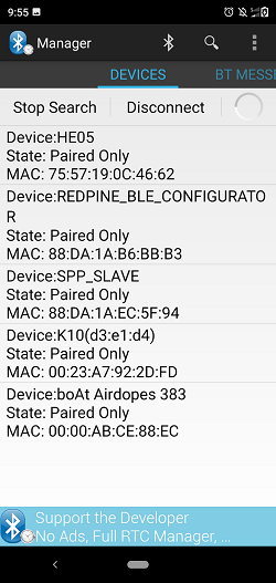
Open Bluetooth SPP manager app on mobile and do the scan until Silicon Labs module (Ex: "SPP_SLAVE") gets present in the scan list
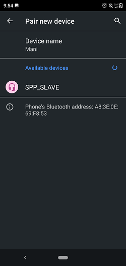
After the successful scan, select the device and initiate pairing to Silicon Labs module.
After initiating pairing, Pairing request will pop-up at smartphone side and issue secret key which is given at Silicon Labs module (PIN_CODE) side.
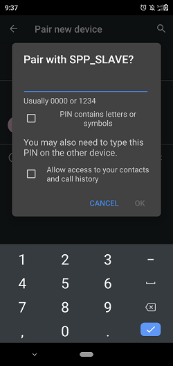
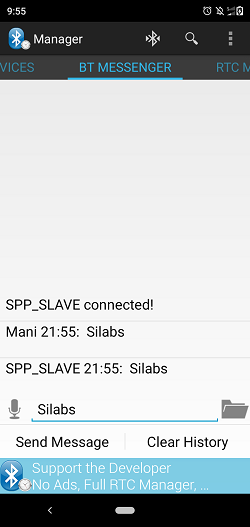
After successful pair, initiate SPP connection to Silicon Labs module and give the secret key for receiving pairing request at remote device side.
After successful SPP Connection, Module go to sleep depending on the selected type of PSP TYPE.
Send some data (Ex: "Silicon Labs signals") from the remote device to Silicon Labs device and same data will send back from Silicon Labs device to remote device. Refer the given image for sending and receiving data from the remote device.
Note down power measurement by connecting the module to Agilent Power Meter.