BT SPP Dual Role with Secure Pairing#
1. Purpose / Scope#
This application demonstrates how to configure RS9116W EVK in Master/Slave mode and establish SPP profile connection with remote Master/Slave device using secure simple paring (SSP) and data exchange between two devices using SPP profile.
In this Application, the module configures in Master mode and waits to accept SPP profile level connection using secure simple pairing (SSP) from remote device. After successful SPP connection, Application will wait for data to receive from connected remote device. If remote device sends data to module, the module receives the data and send back the same data to remote device using SPP profile.
And also in this Application, the module configures in Slave mode and waits to accept SPP profile level connection using secure simple pairing (SSP) from remote device. After successful SPP connection, Application will wait for data to receive from connected remote device. If remote device sends data to module, the module receives the data and send back the same data to remote device using SPP profile.
2. Prerequisites / Setup Requirements#
Before running the application, the user will need the following things to setup.
2.1 Hardware Requirements#
Windows PC with Host interface(UART/ SPI).
Silicon Labs RS9116 Wi-Fi Evaluation Kit
Host MCU Eval Kit. This example has been tested with:
Silicon Labs WSTK + EFR32MG21

Setup Diagram for BT SPP Master Example
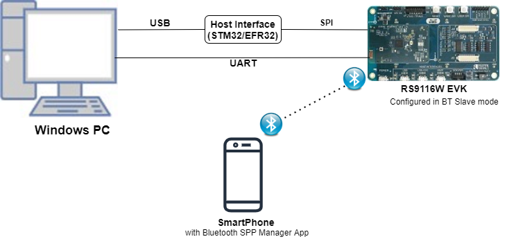
Setup Diagram for BT SPP Slave Example
2.2 Software Requirements#
Embedded Development Environment
For STM32, use licensed Keil IDE
For Silicon Labs EFx32, use the latest version of Simplicity Studio
Download and install the Silicon Labs Bluetooth SPP manager in the android smart phones for testing BT applications. Users can also use their choice of BT apps available in Android/iOS smart phones.
3. Application Build Environment#
3.1 Platform#
The Application can be built and executed on below Host platforms
3.2 Host Interface#
By default, the application is configured to use the SPI bus for interfacing between Host platforms and the RS9116W EVK.
The SAPI driver provides APIs to enable other host interfaces if SPI is not suitable for your needs.
3.3 Project Configuration#
The Application is provided with the project folder containing Keil and Simplicity Studio project files.
Keil Project
The Keil project is used to evaluate the application on STM32.
Project path:
<SDK>/examples/snippets/bt/bt_spp_dual_role_with_secure_pairing/projects/bt_spp_dual_role_with_secure_pairing-nucleo-f411re.uvprojx
Simplicity Studio
The Simplicity Studio project is used to evaluate the application on EFR32MG21.
Project path:
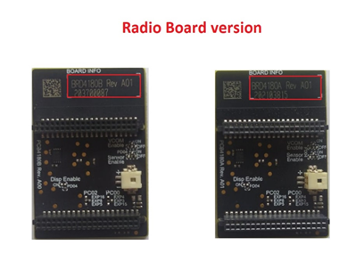
If the Radio Board is BRD4180A or BRD4181A, then access the path
<SDK>/examples/snippets/bt/bt_spp_dual_role_with_secure_pairing/projects/bt_spp_dual_role_with_secure_pairing-brd4180a-mg21.slsprojIf the Radio Board is BRD4180B or BRD4181B, then access the path
<SDK>/examples/snippets/bt/bt_spp_dual_role_with_secure_pairing/projects/bt_spp_dual_role_with_secure_pairing-brd4180b-mg21.slsprojUser can find the Radio Board version as given below
3.4 Bare Metal Support#
This application supports only bare metal environment. By default, the application project files (Keil and Simplicity Studio) are provided with bare metal configuration.
4. Application Configuration Parameters#
The application can be configured to suit your requirements and development environment. Read through the following sections and make any changes needed.
4.1 Open rsi_spp_master_slave.c file and update/modify following macros,
4.1.1 User must update the below parameters
SPP_MODE refers to type of module mode, whether it's master/slave.
#define SPP_SLAVE 0
#define SPP_MASTER 1
#define SPP_MODE SPP_MASTER
#if (SPP_MODE == SPP_MASTER)
#define RSI_BT_LOCAL_NAME "SPP_MASTER"
#else
#define RSI_BT_LOCAL_NAME "SPP_SLAVE"
#endif PIN_CODE refers four bytes string required for pairing process.
#define PIN_CODE "4321" REMOTE_BD_ADDR refers Remote device BD address to connect.
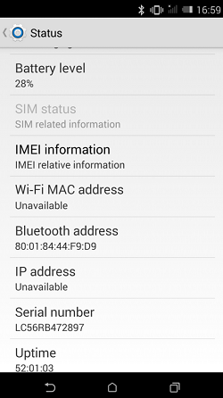
Provide the Smart phone BD address,
#define REMOTE_BD_ADDR "00:1B:DC:07:2C:F0"Note: In the smartphone, User Can check the BD address of Bluetooth device in the following location: Settings/About phone/status/Bluetooth Address
ENABLE_POWER_SAVE refers Module to configure in power save mode
#define ENABLE_POWER_SAVE 0 Note: By default this macro is disabled. User can enable this macro to configure the module in power save.
Following are the non-configurable macros in the application.
BT_GLOBAL_BUFF_LEN refers the number of bytes required by the application and the driver
#define BT_GLOBAL_BUFF_LEN 150004.1.2 Open rsi_wlan_config.h file and update/modify following macros:
#define CONCURRENT_MODE RSI_DISABLE
#define RSI_FEATURE_BIT_MAP FEAT_SECURITY_OPEN
#define RSI_TCP_IP_BYPASS RSI_DISABLE
#define RSI_TCP_IP_FEATURE_BIT_MAP TCP_IP_FEAT_DHCPV4_CLIENT
#define RSI_CUSTOM_FEATURE_BIT_MAP FEAT_CUSTOM_FEAT_EXTENTION_VALID
#define RSI_EXT_CUSTOM_FEATURE_BIT_MAP EXT_FEAT_384K_MODE
#define RSI_BAND RSI_BAND_2P4GHZRole Switch Configuration
Following 3 API's used to get the role, to set the role and to know the status of the role switch
//To know the role of the device rsi_bt_get_local_device_role((int8_t \*)str_conn_bd_addr, &device_state);
//To set the device role to either Master or Slave.(set_role = 0 --\>Master, set_role = 1 --\>Slave) rsi_bt_set_local_device_role((int8_t \*)str_conn_bd_addr, set_role, &device_state);
//To know the status of the Switch Role role_change (uint16_t resp_status, rsi_bt_event_role_change_t \*role_change_status1); The status of the role_change function should return success for successful role switch, otherwise fail.
4.2 Open rsi_spp_master_slave.c file and update/modify following macros,
4.2.1 User must update the below parameters
SPP_MODE refers to type of module mode, whether it's master/slave.
#define SPP_MODE "SPP_SLAVE"
#if (SPP_MODE == SPP_MASTER)
#define RSI_BT_LOCAL_NAME "SPP_MASTER"
#else
#define RSI_BT_LOCAL_NAME "SPP_SLAVE"
#endif PIN_CODE refers four bytes string required for pairing process.
#define PIN_CODE "4321"4.2.2 The desired parameters are provided below. User can also modify the parameters as per their needs and requirements. Following are the non-configurable macros in the application.
BT_GLOBAL_BUFF_LEN refers the number of bytes required by the application and the driver
#define BT_GLOBAL_BUFF_LEN 150004.3 Open rsi_wlan_config.h file and update/modify following macros:
#define CONCURRENT_MODE RSI_DISABLE
#define RSI_FEATURE_BIT_MAP FEAT_SECURITY_OPEN
#define RSI_TCP_IP_BYPASS RSI_DISABLE
#define RSI_TCP_IP_FEATURE_BIT_MAP TCP_IP_FEAT_DHCPV4_CLIENT
#define RSI_CUSTOM_FEATURE_BIT_MAP FEAT_CUSTOM_FEAT_EXTENTION_VALID
#define RSI_EXT_CUSTOM_FEATURE_BIT_MAP EXT_FEAT_384K_MODE
#define RSI_BAND RSI_BAND_2P4GHZRole Switch Configuration
Following 3 API's used to get the role, to set the role and to know the status of the role switch
//To know the role of the device rsi_bt_get_local_device_role((int8_t \*)str_conn_bd_addr, &device_state);
//To set the device role to either Master or Slave.(set_role = 0 --\>Master, set_role = 1 --\>Slave) rsi_bt_set_local_device_role((int8_t \*)str_conn_bd_addr, set_role, &device_state);
//To know the status of the Switch Role role_change (uint16_t resp_status, rsi_bt_event_role_change_t \*role_change_status1); |The status of the role_change function should return success for successful role switch, otherwise fail.
5. Testing the Application#
User has to follow the below steps for the successful execution of the application.
5.1 Loading the RS9116W Firmware#
Refer Getting started with PC to load the firmware into RS9116W EVK. The firmware binary is located in <SDK>/firmware/
5.2 Building the Application on the Host Platform#
5.2.1 Using STM32#
Refer STM32 Getting Started
Open the project
<SDK>/examples/snippets/bt/bt_spp_dual_role_with_secure_pairing/projects/bt_spp_dual_role_with_secure_pairing-nucleo-f411re.uvprojxin Keil IDE.Build and Debug the project
Check for the RESET pin:
If RESET pin is connected from STM32 to RS9116W EVK, then user need not press the RESET button on RS9116W EVK before free run.
If RESET pin is not connected from STM32 to RS9116W EVK, then user need to press the RESET button on RS9116W EVK before free run.
Free run the project
Then continue the common steps from Section 5.3
5.2.2 Using EFX32#
Refer EFx32 Getting Started
Import the project from
<SDK>/examples/snippets/bt/bt_spp_dual_role_with_secure_pairing/projectsSelect the appropriate .slsproj as per Radio Board type mentioned in Section 3.3
Compile and flash the project in to Host MCU
Debug the project
Check for the RESET pin:
If RESET pin is connected from STM32 to RS9116W EVK, then user need not press the RESET button on RS9116W EVK before free run
If RESET pin is not connected from STM32 to RS9116W EVK, then user need to press the RESET button on RS9116W EVK before free run
Free run the project
Then continue the common steps from Section 5.3
5.3 Common Steps#
Executing the Application for Master Mode
Power on Bluetooth in smart phone and put it in visible mode to all Bluetooth devices(Can be done through "Bluetooth SPP Manager" app. As shown in the below image.
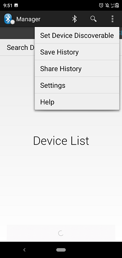
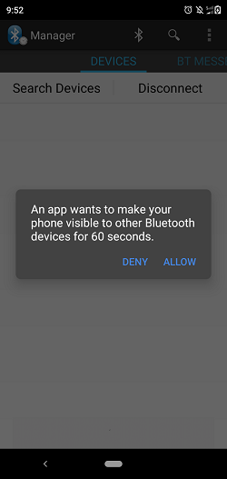
Tap the "Set Device Discoverable" option in the App. By again tapping the "Allow/Yes" in the pop-up, the module will be discoverable for 60Seconds.
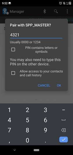
After the program gets executed, Silicon Labs module initiates basic connection with the remote device (Smart phone). User has to provide PIN_CODE at remote device for successful connectivity. Find below images for connection at remote device.
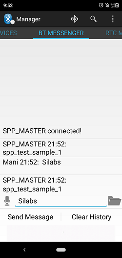
After a successful physical level connection, in smartphone, "connection established" notification message will be displayed which means profile level connection is completed.
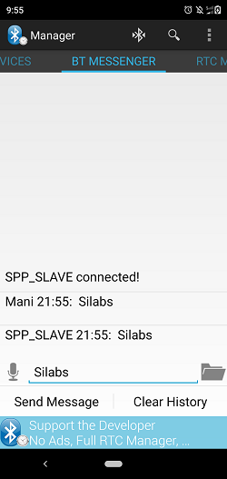
After successful SPP Connection in mobile side, go to BT_MESSENGER tab which is next to DEVICES tab. Write some data (Ex: "Silicon Labs signals") and call "Send Message" option in that app. we can see that the same message has been exchanged between two modules which is kind of loopback test.
Executing the Application for Slave Mode
After the program gets executed, the Silicon Labs module initializes the SPP profile and waits for the incoming connection.
Open the Bluetooth setting present in the mobile. Now scan for available devices in the settings menu until the Silicon Labs module (Ex: "SPP_SLAVE") gets listed in that scan list.
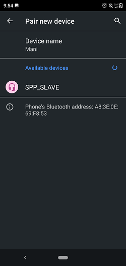
After the successful scan, select the device and initiate pairing to Silicon Labs module.
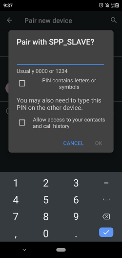
After initiating pairing, the Pairing request will pop-up at the smartphone side and issue a secret key which is given at the Silicon Labs module (PIN_CODE ) side. Then the module successfully establishes the physical level connection.
Open the "SPP Manager app", Tap on the "search devices" option visible in the app you will get scan results as shown below
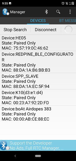
After tapping on the SPP_SLAVE in that scan list, it will initiate profile level connection as it already paired through physical level process.
After successful SPP Connection in mobile side, go to BT_MESSENGER tab which is next to DEVICES tab. Write some data (Ex: "Silicon Labs signals") and call "Send Message" option in that app. we can see that the same message has been exchanged between two modules which is kind of loopback test.